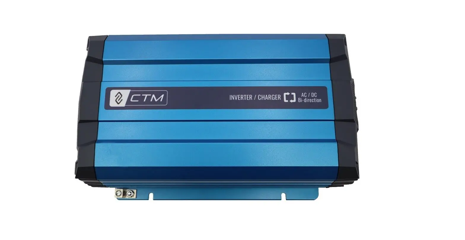
CTM SC-1200 series 1200W Pure Sine Wave Inverter / Charger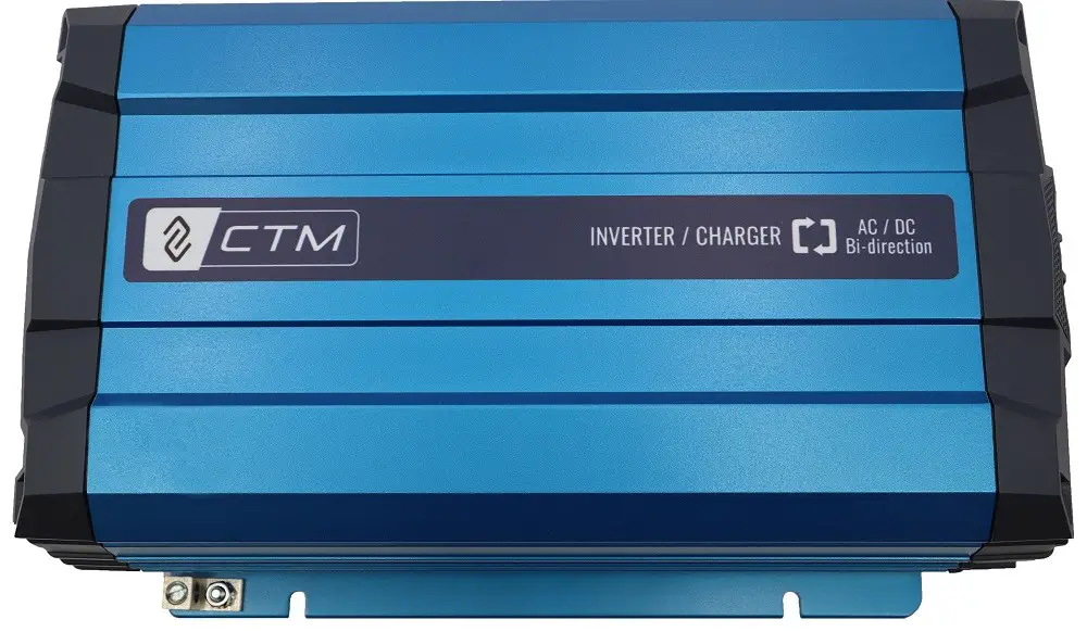
Feature
- Bi-directional All-in-One Design
- Compact Size
Highly Integration = Installation hassle-free - Certifed by UL
UL458 & Supplement SA / CSA C22.2 No. 107.1-01
UL1741 / CSA C22.2 No. 107.1-01 / KKK-A-1822F (For Ambulance) - 5-in-1 Operating Modes
1. Inverter mode 2. Charger mode 3. Power Sharing 4. Power Generation
5. Power Support
| SC-1200-112 | SC-1200-124 | SC-1200-212 | SC-1200-224 | ||
| Inverter Mode | |||||
| Input | Nominal Voltage | 12 VDC | 24 VDC | 12 VDC | 24 VDC |
| Input Voltage Range (±0.5V) | Input Voltage Range (±0.5V) | 21.0 ~ 33.0 VDC | 10.5 ~ 16.5 VDC | 21.0 ~ 33.0 VDC | |
| Input Over-Voltage Protection (±0.5V) | 16.5 VDC | 33.0 VDC | 16.5 VDC | 33.0 VDC | |
| Input Over-Voltage Warning (±0.5V) | 15.5 VDC | 31.0 VDC | 15.5 VDC | 31.0 VDC | |
| Input Under-Voltage Protection (±0.5V) | 10.5 VDC | 21.0 VDC | 10.5 VDC | 21.0 VDC | |
| Input Current (Max) | 132 A | 66 A | 132 A | 66 A | |
| No Load Current | < 3.0 A @12.5V | < 1.5 A @25V | < 3.0 A @12.5V | < 1.5 A @25V | |
| Stand-By Current | < 0.4 A | < 0.2 A | < 0.4 A | < 0.2 A | |
| Output | Continuous Output Power | 1200 VA ± 3% | |||
| Surge Power | Load 101%~115% (1 Min) / 2400 VA (2 Sec) | ||||
| Frequency | 50/60 Hz ± 0.3 Hz (User-selectable) | ||||
| Output Voltage | 100 / 110 / 115 / 120VAC ±3% | 200 / 220 / 230 / 240VAC ±3% | |||
| Max. E‑ciency (Full Load) | 89% | 90% | 89% | 90% | |
| Output Waveform | Pure Sine Wave (THD < 5% @ 12.5V/25V/115VAC, linear load) / (THD < 3% @ 12.5V/25V/230VAC, linear load) | ||||
| INV. AC Output* | 12A MAX | 6A MAX | |||
| AC Output* | 30A MAX | 22A MAX | |||
| Protection | Input Protection | Over / Under Voltage, Reverse Polarity (Internal Fuse) | |||
| AC Output Protection | Short-Circuit, Overload | ||||
| AC Input Protection | 30 Amp Circuit Breaker | 16 Amp Circuit Breaker | |||
| Battery Temperature protection | By a RJ-11 connector to battery Temperature sensor | ||||
| Charger Mode | |||||
| AC input | Nominal Voltage / Frequency | 110 VAC, 50 / 60Hz (User-selectable) | 230 VAC, 50 / 60Hz (User-selectable) | ||
| Input Voltage Range | 90 ~ 132 VAC | 180 ~ 264 VAC | |||
| Input Frequency Range | 50Hz:47 ~ 53 Hz / 60Hz:57 ~ 63 Hz | ||||
| Nominal Current | 8.2A (@110VAC) | 3.9A (@230VAC) | |||
| E‑ciency (Max.) | >88% | ||||
| AC Input* | 30 A MAX | 16 A MAX | |||
| Power Factor Correction (PFC) | >0.95 (Max.) | ||||
| Auxiliary DC Output | Output Voltage | Battery Voltage | |||
| Output Current | 20A Max | ||||
| DC Output | Charging Current Range | 12.5 / 25 / 37.5 / 50A | 6.25 / 12.5 / 18.75 / 25A | 12.5 / 25 / 37.5 / 50A | 6.25 / 12.5 / 18.75 / 25A |
| Max. Output Voltage | 14.4 VDC@ GEL TYPE | 28.8 VDC @ GEL TYPE | 14.4 VDC @ GEL TYPE | 28.8 VDC @ GEL TYPE | |
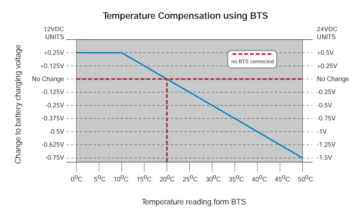
| Battery Temperature Compensation | -25 mV per ℃ | -50 mV per ℃ | -25 mV per ℃ | -50 mV per ℃ | |
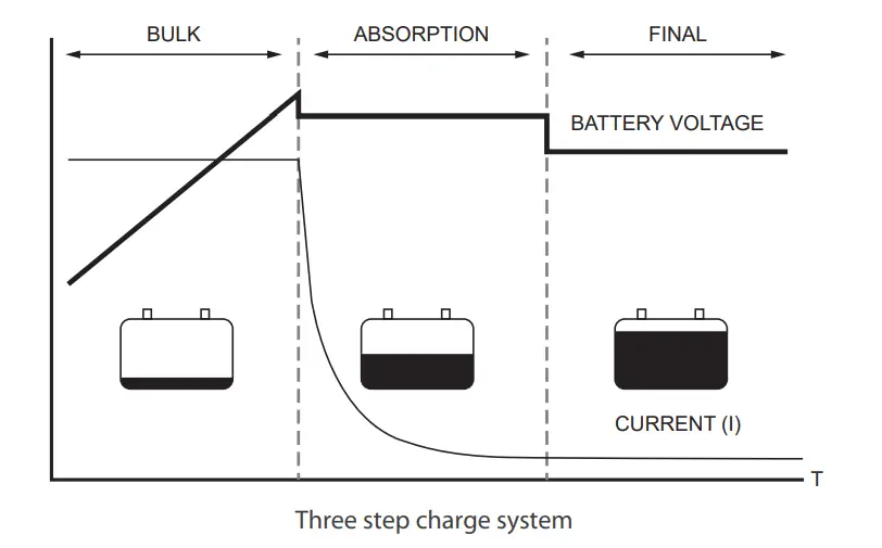
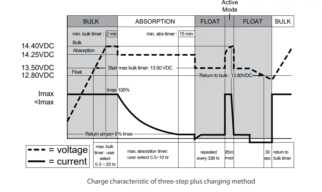
| Battery Control (3-stage Battery Chargers) | Bulk / Absorption / Float | ||||
| Signal and Control | Remote Control Panel (Optional) | CR-20C / CR-16B / CR-8 | |||
| Dry Contact Terminal | By a relay | ||||
| Relay Specication | 30 Amp / 120 VAC @ 110V system | 16 Amp / 250 VAC @ 230V system | |||
| Environment | |||||
| Operating Temperature | Full Load | -20 ℃ ~ 50 ℃* | |||
| Range | Power de-rating | 40 W / ℃, 51~60 ℃ | |||
| Storage | 30 ℃~70 ℃ | ||||
| Operating Humidity Range | Max 93%, Non-condensing | ||||
| Cooling | Temperature & Load Controlled Cooling Fan | ||||
| Safety Standards | UL458 & Supplement SA / UL1741 | EN 62368-1 | |||
| E-mark | Certied CISPR 25; ISO7637-2 | ||||
| EMC Standards | EN55032 Class A*, EN55024 Class A* EN61000-3-2, 3-3 , EN61000-4-2, 3, 4, 5, 6, 8, 11 | ||||
| Other | |||||
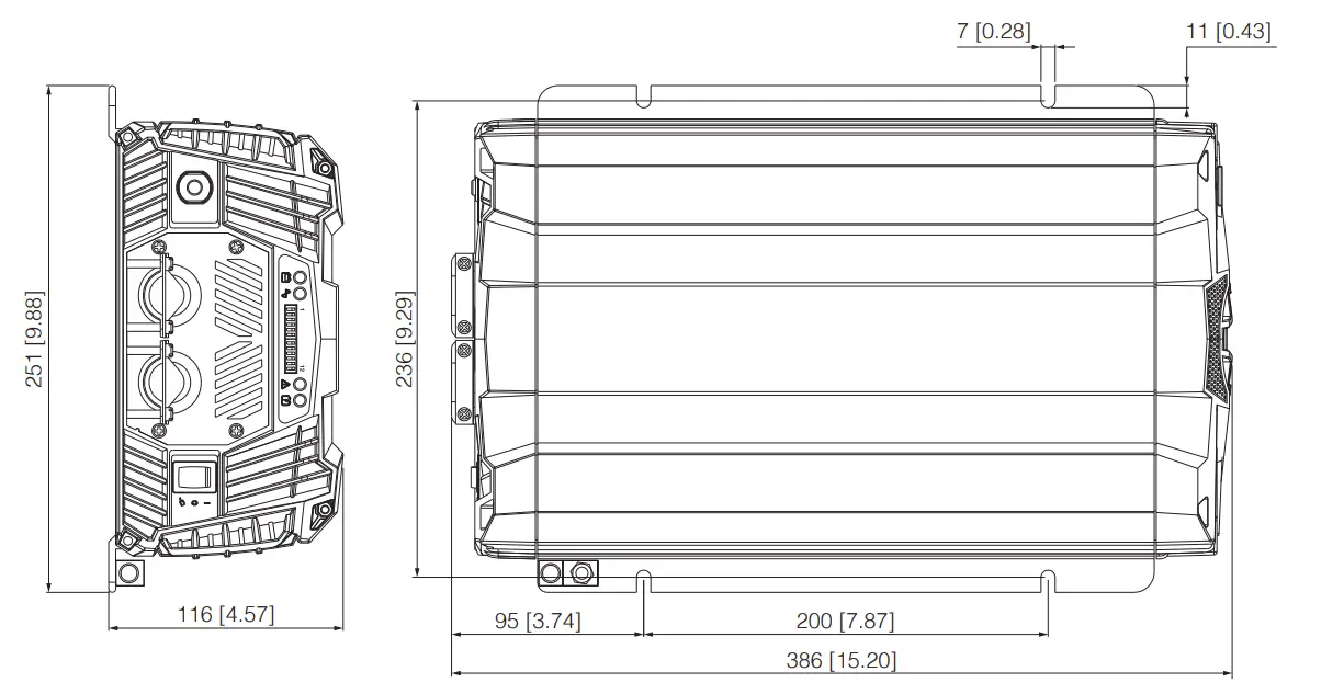
| Dimension (W x H x D) | 251 x 116 x 386mm | ||||
| Net Weight | 4.55Kg | ||||
*Max Inverter output define inverter 100% load output at Vac =100V / 200V
*Max AC output define AC input current + Inverter output current, cannot over AC input limit.
*Max AC input current Limit by the Breaker
*For SC-1200 -112 and -124, the operating temperature range certified by UL Safety Standard is -20°C ~ 40°C.
*SC series is a class A product. In a domestic environment this product may cause radio interference in which case the user may be required to take adequate measures
The Battery Charger
Front panel
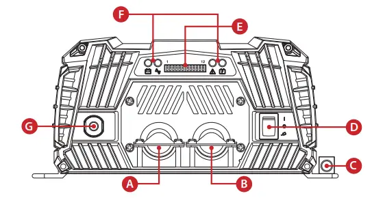
Ⓐ AC Output
Ⓑ AC Input
Ⓒ Chassis ground
Ⓓ Main switch
Ⓔ DIP switch
Ⓕ Function LED
Ⓖ AC input breaker
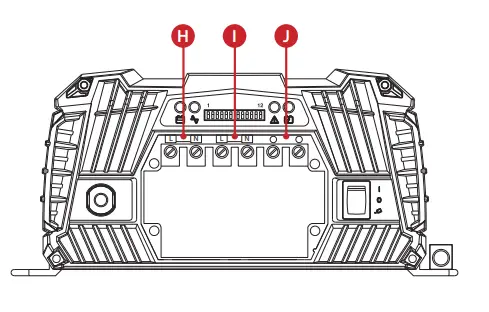
Ⓗ AC Output terminal (L/N)
Ⓘ AC Input terminal (L/N)
Ⓙ AC In/Output ground terminal
Function LED
![]() BAT : Display input voltage
BAT : Display input voltage
| LED Status | DC12V | DC24V |
| Red | < 11.0V | < 22.0V |
| Orange | 11.0 ~ 11.5V | 22.0 ~ 23.0V |
| Green | 11.5 ~ 15.0V | 23.0 ~ 30.0V |
| Orange | 15.0 ~ 15.5V | 30.0 ~ 31.0V |
| Red | >15.5V | >31.0V |
![]() Load: Display AC loads (PF=1)
Load: Display AC loads (PF=1)
| LED Status | SC-1200 / SC-2000 |
| Red | > 115% |
| Orange | 100 ~ 115% |
| Green | 0 ~ 100 % |
| Dark | Charger Mode |
![]() Status : Display System Status
Status : Display System Status
| LED Status | Status |
| Green | Normal |
| Green Slow Blink | OTP |
| Green Fast Blink | UTP |
| Orange | PLL/Frequency Fail |
| Orange Slow Blink | AC in UVP/OVP |
| Orange Fast Blink | AC IN OCP |
| Red | OLP / SCP |
| Red Slow Blink | Battery UVP |
| Red Fast Blink | Battery OVP |
![]() Charger : Display Charger Stage
Charger : Display Charger Stage
| LED Status | SC-1200 / SC-2000 |
| Orange Blink | Bulk |
| Orange | Absorption |
| Green | Float |
| Red | Charger Error |
| Green Fast Blink | Active |
| Green Slow Blink | Equalization |
| Dark | Inverter Mode |
The Battery Charger
Mechanical Drawings
Dip switch Function
| Dip Switch | Function |
| S1 | Output Voltage Select |
| S2 | |
| S3 | Frequency Select |
| S4 | AC Input Current Limit Select |
| S5 | |
| S6 | |
| S7 | Battery Type Select |
| S8 | |
| S9 | Charger Current Select |
| S10 | |
| S11 | DC Source on/off |
| S12 | Saving Function on/off |
AC Input Current Limit Select (S4,S5,S6)
| AC Input Current 100~120V / 200~240V | S4 | S5 | S6 |
| 3A / 2A | OFF | OFF | OFF |
| 6A / 4A | ON | OFF | OFF |
| 9A / 6A | OFF | ON | OFF |
| 12A / 8A | ON | ON | OFF |
| 15A / 10A | OFF | OFF | ON |
| 20A / 12A | ON | OFF | ON |
| 25A / 14A | OFF | ON | ON |
| 30A / 16A | ON | ON | ON |
Charger Current Select Function (S9,S10)
| Charger Current | S9 | S10 |
| 25% | OFF | OFF |
| 50% | ON | OFF |
| 75% | OFF | ON |
| 100% | ON | ON |
Saving Function Switch ON/OFF Function (S12)
| Saving function | S12 |
| OFF | OFF |
| ON | ON |
Output Voltage switch Function (S1,S2)
| Output Voltage | S1 | S2 |
| 100V / 200V | OFF | OFF |
| 110V / 220V | ON | OFF |
| 115V / 230V | OFF | ON |
| 120V / 240V | ON | ON |
Output Frequency switch Function (S3)
| Frequency | S3 |
| 50HZ | OFF |
| 60HZ | ON |
Battery Type Select Function (S7,S8):
| Battery Type | S7 | S8 |
| GEL | OFF | OFF |
| Flooded | ON | OFF |
| AGM | OFF | ON |
| Customer | ON | ON |
| Battery Type | Bulk | Absorption | Float |
| GEL | 14.40V | 14.10V | 13.60V |
| Flooded | 14.70V | 14.60V | 13.40V |
| AGM | 14.70V | 14.30V | 13.10V |
| Customer | 14.70V | 14.50V | 13.50V |
DC Source Output On/Off Function (S11)
| ESB function | S11 |
| OFF | OFF |
| ON | ON |
Power Saving Load Function
| SC series -212, -224 | Default: 40VA |
| Entering the saving power | Load<32VA |
| Wake up the saving power | Load>40VA |
| SC series -112, -124 | Default: 20VA |
| Entering the saving power | Load<16VA |
| Wake up the saving power | Load>20VA |
Rear panel
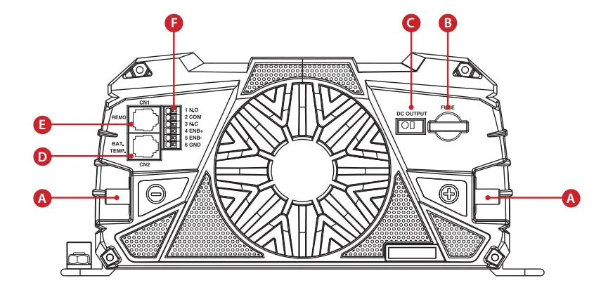
BAT. TEMP. Port (RJ-11) \
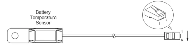
| Pin Number | Signal Description |
| 1 | Not used |
| 2 | GND |
| 3 | Batteries temperature sensor |
| 4 | Battery Detect |
| 5 | Not used |
| 6 | Not used |
Remote Port (RJ-11)
| Pin Number | Signal Description | |
| 1 | Reserved | — |
| 2 | GND | The same polarity as the battery negative side |
| 3 | RXD | RS232 RXD |
| 4 | TXD | RS232 TXD |
| 5 | RMT | Remote controller panel (positive) |
| 6 | VCC | Internal power for remote controller |
Remote Control & Green Terminal
Remote control green terminal may be connected to a Form C relay for “FAULT” indication. When “FAULT” occurs, the relay switches.
Remote control terminal
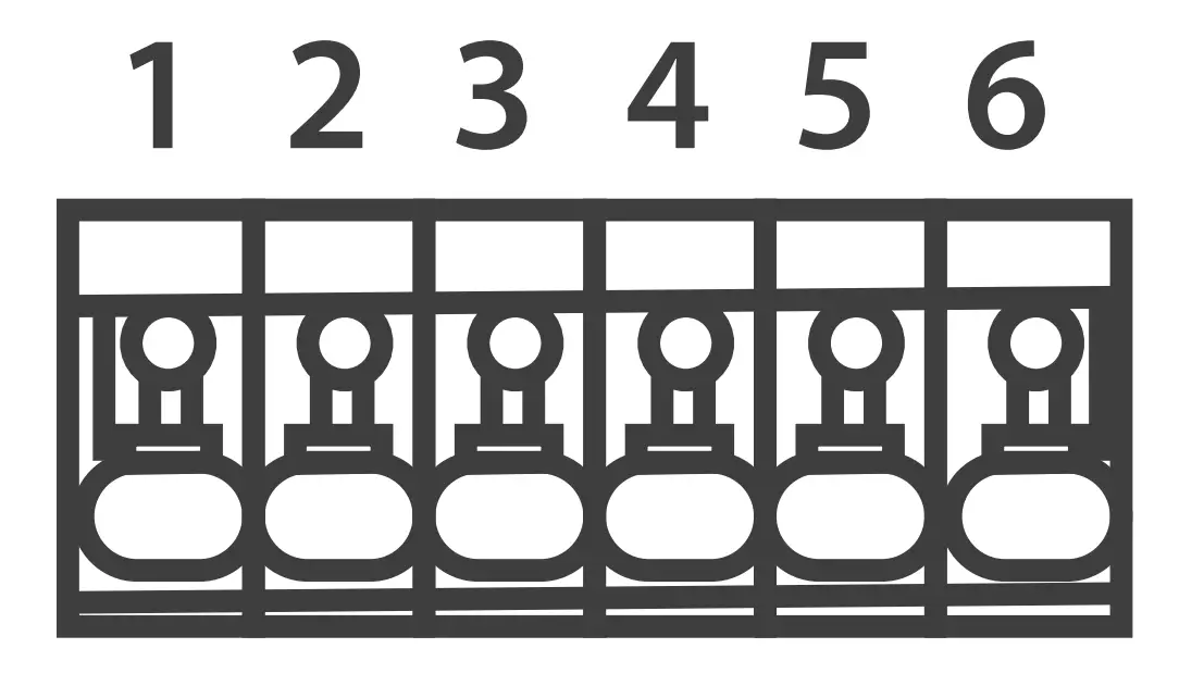
| Item | Description | Item | Description |
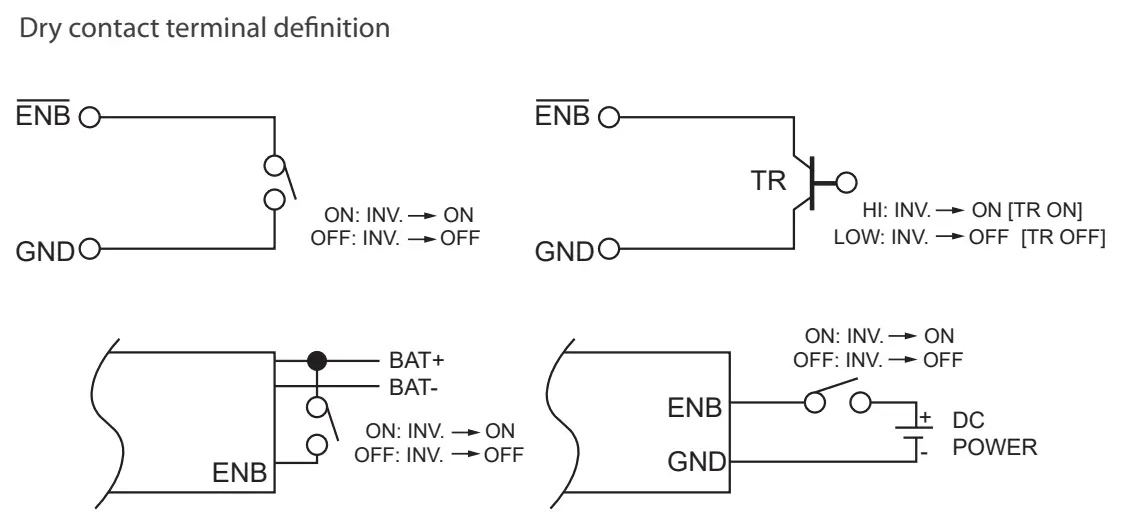
| 1 | Dry contact (Normal Open) | 4 | Enable+ (ENB) |
| 2 | Common | 5 | Enable- (ENB) |
| 3 | Dry contact (Normal Closed) | 6 | Ground |
Dry contact terminal definition
Specifications of the Relay
| Maximum Voltage | Load | Contact Rating | Number of operations | Operating/Storage Temperature | |
| N.O | N.C | ||||
| 250 VAC | Resistive | 1 A | — | 100,000 |
-30℃~75℃ |
| 250 VAC | Resistive | — | 1 A | — | |
| 24 VDC | Resistive | 1 A | — | — | |
| 24 VDC | Resistive | — | 1 A | — | |