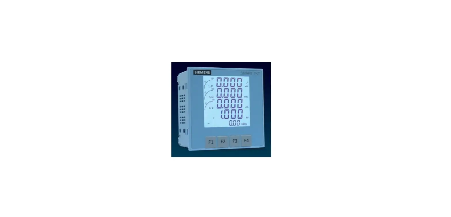

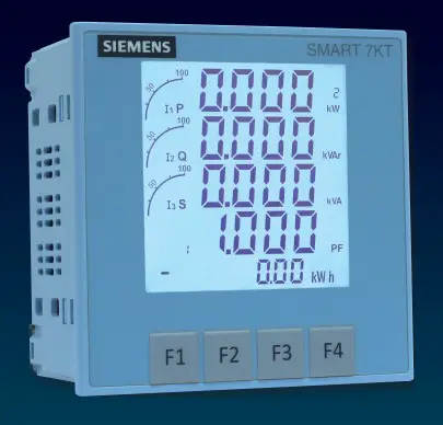
SIEMENS 7KT0310 SMART 7KT Multifunction Meter
Introduction
Purpose of this document This present manual describes the SMART 7KT multifunction meter. It is intended for the use of:
- Planners
- Plant operators
- Commissioning engineers
- Service and maintenance personnel
Required basic knowledge A general knowledge of the field of electrical engineering is required to understand this manual. Knowledge of the relevant safety regulations and standards is required for installing and connecting the device.
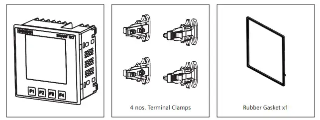
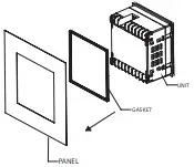
Components of the product The carton for the products contain
- 1 SMART 7KT meter
- 1 set of clamps (4 clamps) for mounting the meter on the panel door
- 1 Gasket
- 1 Operating instruction
Safety precautions
Please read and understand these instructions before installing, operating, or maintaining the equipment.
DANGER Hazardous voltage. Will cause death or serious injury. Turn off and lock out all power supply to this device before working on this device. Replace all covers before power supplying this device is turned on.
All safety related codifications, symbols and instructions that appear in this operating manual or on the equipment must be strictly followed to ensure the safety of the operating personnel as well as the instrument. If the equipment is not used in a manner specified by the manufacturer it might impair the protection provided by the equipment. Do not use the equipment if there is any mechanical damage. Ensure that the equipment is supplied with correct voltage.
CAUTION:
- Read complete instructions prior to installation and operation of the unit.
- Risk of electric shock.
- The equipment in its installed state must not come in close proximity to any heating sources, oils, steam, caustic vapors or other unwanted process by products.
Technical Specification
| Display | |
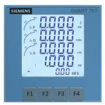
| Type and specifics | • Large backlit Liquid Crystal display • 4 Lines with 4 digits each to show measured values • 5th Line with 8 digits to show energy values • Graph for current loading indication |
| Size of display (mm x mm) | 60.3 mm x 60.3 mm |
| LCD Indications | I Integration of energy PRG Unit is in configuration menu Communication in progress MAX DMD Maximum and Minimum Demand Power |
| Display update time | 1 sec. for all parameters |
| Display scrolling | Automatic or Manual (Programmable) |
| Password protected | Yes |
| Wiring input | 3 Ø – 4 wire, 3 Ø – 3 wire, 1 Ø – 2 wire |
| Measuring inputs | |
| Rated input voltage | 11 to 300V AC (L-N); 19 to 519V AC (L-L); Installation Category III (600V) |
| Frequency range | 45-65 Hz |
| Rated input current | Nominal 1A / 5A AC (Min-11mA , Max-6A for 5A) |
| Auxiliary supply | 95V to 240V AC, ±10%, 50/60Hz (±5%) |
| Memory (behaviour in the event of power failure) | Retains all energy values, On hours counter value and configuration settings in case of power failure |
| CT/PT Settings | |
| CT Type | Measurement C.T, FS 10 |
| CT Primary | 1A / 5A to 10,000A (Programmable for any Value) • 1A to 10,000A when CT secondary is 1 • 5A to 10,000A when CT secondary is 5 |
| CT Secondary | 1A or 5A (Programmable) |
| Burden | 0.5 VA@5A per phase |
| PT Primary | 100V to 500kV (Programmable for any value) |
| PT Secondary | 100V to 500V AC (L-L) (Programmable for any value) |
| Power consumption | Less than 8VA |
| Environmental conditions | • Temperature (Operating): -10°C to 55°C • Temperature (Storage): -20°C to 75°C • Humidity: Up to 85% non-condensing • Altitude: of up to 2000 meters • Indoor use • Pollution degree II |
| Mounting | Panel-door mounting |
| Protection Class | II |
| Degree of protection according to IEC 60529 | Front: IP 65 (when mounted on the panel door) Rear: IP20 |
| Overvoltage Category | III |
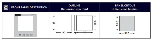
| Dimensions and weight | L x B x D: 96 x 96 x 55 mm Weight: 360 gms |
| Digital Input | |
| Number | 1 |
| Input voltage | Maximum input voltage: 28 V DC Switching threshold for signal “1“ > V DC |
| Input current | For signal “1”: typ mA |
Measured variables
| Measured variable | On display | On communication |
| Voltage V L-N, V L-L | ● | ● |
| Current | ● | ● |
| Neutral current | ● | ● |
| Frequency | ● | ● |
| Power factor | ● | ● |
| Active power | ● | ● |
| Reactive power | ● | ● |
| Apparent power | ● | ● |
| Active energy (Import, Export, Total) | ● | ● |
| Reactive energy (Import, Export, Total) | ● | ● |
| Apparent energy | ● | ● |
| Max demand (current) over set demand period | ● | ● |
| Max demand (active, reactive and apparent power) over set demand period | ● | ● |
| Phase angle of 3 phases | ● | – |
| THD% (Current) | ● | ● |
| THD% (Voltage) | ● | ● |
| Individual harmonics (Current) | – | ● |
| Individual harmonics (Voltage) | – | ● |
Not there Available
Measuring accuracy
| Measured variable | Error limits |
| Voltage V L-N | 0.5% of Full scale (300V AC) |
| Voltage V L-L | Full scale 0.5% |
| Current | Phase Current: 0.5% of full scale Neutral current: 1% of full scale |
| Frequency | 0.1% For L-N Voltage >20V, For L-L Voltage >35V |
| Power factor | 0.01 Digit |
| Active power | 1% |
| Reactive power | 1% |
| Apparent power | 1% |
| Active energy | Class 1 (as per IEC 62053-21) |
| Reactive energy | Class 2 (as per IEC 62053-23) |
| Apparent energy | 1% |
| Phase angle of 3 phases | 1% |
| THD (Current) | 1% |
| THD (Voltage) | 1% |
| Harmonics (Current) | 1% |
| Harmonics (Voltage) | 1% |
When measuring on external current transformers or voltage transformers, the accuracy of the measurement depends on the quality of the transformer.
IEC Standards
| Description | Standard |
| Energy accuracy | IEC 62053-21 | Active energy |
| EMC requirements | IEC 61326-1: 2012 |
| Degree of protection test (IP) | IEC 60529 |
| Safety requirements | IEC 61010-1:2010 and IEC 61010-2-030:2010 |
| Vibration and mechanical shock | IEC 62052-11 |
Certifications
SMART 7KT multifunction meter conforms to IEC standards, IPC electronics assembly standard.
Assembly
Installation
For installing the meter Prepare the panel cutout with proper dimensions as shown below.
- Insert unit into the panel

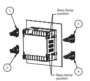
- Position the clamps (as shown in the figure) and push the same into the slots in their respective locations.

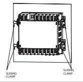
- Push/Slide all 4 clamps towards the panel evenly till the lowest possible tooth of the clamp is engaged. Ensure the meter is properly tightened and it does not move.

Note: Terminal screw tightening torque: 0.7 N-m to 0.8 N-m (6 In-Lb to 7 In-Lb)
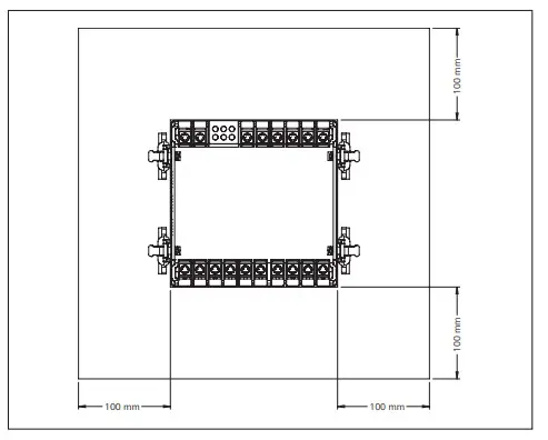
The distance to be maintained between two meters while mounting on a panel door should be at least 100 mm.
Installation Guidelines
- This equipment, being built-in-type, normally becomes a part of main control panel and in such case the terminals do not remain accessible to the end user after installation and internal wiring.
- Conductors must not come in contact with the internal circuitry of the equipment or else it may lead to a safety hazard that may in turn endanger life or cause electrical shock to the operator.
- Circuit breaker or mains switch must be installed between power source and supply terminals to facilitate power ‘ON’ or ‘OFF’ function. However this switch or breaker must be installed in a convenient position normally accessible to the operator.
- Before disconnecting the secondary of the external current transformer from the equipment, make sure that the current transformer is short circuited to avoid risk of electrical shock and injury.
- The equipment shall not be installed in environmental conditions other than those mentioned in this manual.
- The equipment does not have a built-in-type fuse. Installation of external fuse of rating 275V AC / 0.5Amp for electrical circuitry is highly recommended.
- Remove the scratch-guard from the meter display during commissioning of the panel.
Wiring Guidelines
- To prevent the risk of electric shock, power supply to the equipment must be kept OFF while doing the wiring arrangement.
- Wiring shall be done strictly according to the terminal layout. Confirm that all connections are correct.
- Use lugged terminals.
- To reduce electromagnetic interference use of wires with adequate ratings and twists of the same in equal size shall be made with shortest connections.
- Layout of connecting cables shall be away from any internal EMI source.
- Cable used for connection to power source, must have a cross-section of 1mm2 to 2.5mm2.These wires shall have current carrying capacity of 6A.
- Copper cable should be used (Stranded or Single core cable).
For demounting the meter
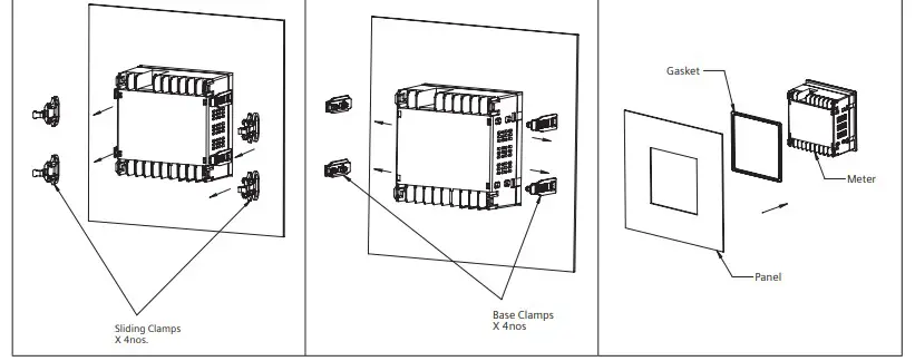
- Pull the arm of the sliding clamps in outward direction (opposite to meter) and drag the sliding clamps away from the panel.
- Dis-assemble the snap fitted base clamps from the meter using a screw-driver
- Push the meter from back side out of the panel window and remove the gasket from the meter
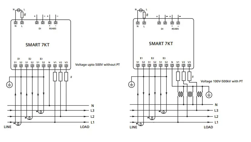
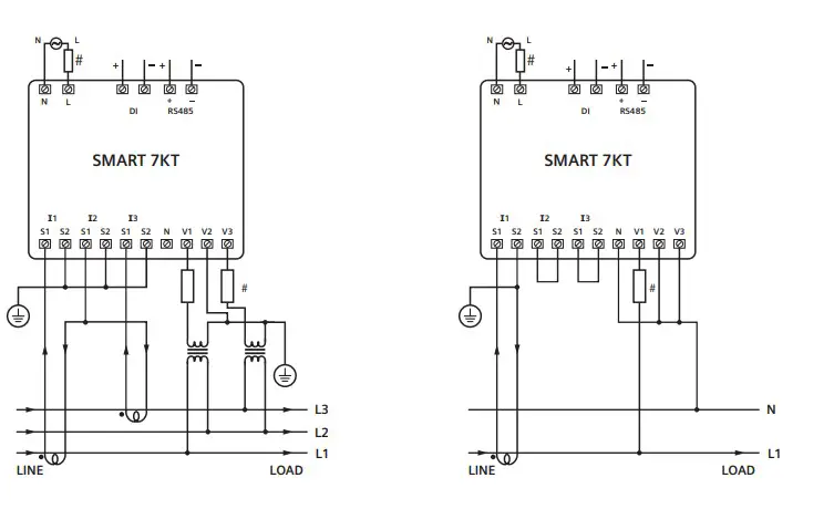
Connection
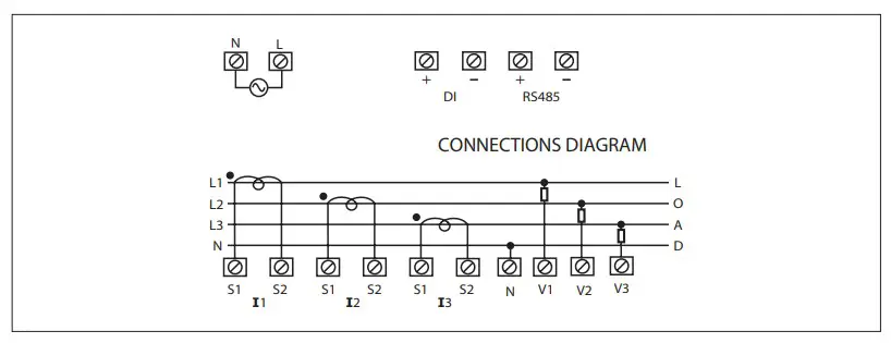
Circuit Diagram
- 3 Phase 4-Wire (commonly used) 3 Ø – 4 Wire, 3 CT’S

- 3 Ø – 4 Wire, 3 CT’S and 3 PT’S
- 3 Phase 3-Wire 3 Ø – 3 Wire, 2CTs and 2PTs

- 1 Phase 2-Wire 1 Ø – 2 Wire, 1 CT
Configuration
There are 4 dedicated keys labelled as F1, F2, F3, F4. Use these 4 keys to read meter parameters. Simply press these keys to read the parameters. The keys have multiple assignments. Function assignments and key labeling change according to the context of operator input.
A short press on the key triggers the function once. Holding the key down for longer switches on the autorepeat function after approximately 1 s. The function of the key is triggered repeatedly while the key is held down. Autorepeat is useful, for example, for fast incrementing of values when parameterizing the device.
For reading serial number Press F3 key for 5 sec. to display 8-digit serial number only for 5 sec. at 5th line of display
Automatic / manual mode Press F4 key for 3 seconds to toggle between Automatic and Manual mode.
Note: By default, unit operates in automatic mode. In automatic mode online pages scroll automatically at the rate of 5 seconds per page. In automatic mode when any key is pressed, unit temporarily switches to manual mode and the appropriate page is displayed. If any key is not pressed for 5 sec, unit resumes automatic mode.
Password to start configuration When the meter is brought into the configuration mode by pressing keys F3+F4, the first page that is displayed is the password page which shows the password 0000. Enter the password 1000 which is the default factor-set password by pressing the F1 key to move curser left or right by one digit at a time and F2 or F3 keys for increasing or decreasing parameter values. After you enter the password of 1000, press F4 key to go to the next page which is the password change page and continue with parameterization.
For the configuration setting mode
- Press F3 + F4 keys for 3 seconds to enter or exit from the Configuration menu.
- Use F1 key to move curser left or right by one digit at a time
- Use F2 or F3 keys for increasing or decreasing parameter values
- Press F2+F4 key to go back to previous page
Parameterization with function keys
| Config. page | Function | Range or Selection | Factory Setting |
| Password | 0000 to 9998 | 1000 | |
| 1 | Change Password | No / Yes | No |
| 1.1 | New Password | 0000 to 9998 | 1000 |
| 2 | Network Selection | 3P4W, 3P3W, 1P2W-P1, 1P2W-P2 and 1P2W-P3 | 3P4W |
| 3 | CT Secondary | 1A or 5A | 5 |
| 4 | Ct Primary | 1A, 5A to 10,000A | 5 |
| 5 | Pt Secondary | 100V to 500V | 350 |
| 6 | Pt primary | 100V to 500kV | 350 |
| 7 | Slave Id | 1 to 255 | 1 |
| 8 | Baud Rate | 300, 600, 1200, 2400, 4800, 9600 and 19200 (bps) | 9600 |
| 9 | Parity | None, Odd, Even | None |
| 10 | Stop Bit | 1 or 2 | 1 |
| 11 | Back Light | 0 to 7200 sec. | 0000 |
| 12 | Demand interval method | Sliding / Fixed | Sliding |
| 13 | Demand interval duration | 1 to 30 | 15 |
| 14 | Demand interval length | 1 to 30 min | 1 |
| 15 | Max Page Auto | 1 to 22 | 22 |
| 16 | Change Page Sequence | No / Yes | No |
| 16.01 | Page sequence 1 | 1 to 22 | 1 |
| 16.02 | Page sequence 2 | 1 to 22 | 2 |
| 16.03 | Page sequence 3 | 1 to 22 | 3 |
| 16.04 | Page sequence 4 | 1 to 22 | 4 |
| 16.05 | Page sequence 5 | 1 to 22 | 5 |
| 16.06 | Page sequence 6 | 1 to 22 | 6 |
| 16.07 | Page sequence 7 | 1 to 22 | 7 |
| 16.08 | Page sequence 8 | 1 to 22 | 8 |
| 16.09 | Page sequence 9 | 1 to 22 | 9 |
| 16.10 | Page sequence 10 | 1 to 22 | 10 |
| Config. page | Function | Range or Selection | Factory Setting |
| 16.11 | Page sequence 11 | 1 to 22 | 11 |
| 16.12 | Page sequence 12 | 1 to 22 | 12 |
| 16.13 | Page sequence 13 | 1 to 22 | 13 |
| 16.14 | Page sequence 14 | 1 to 22 | 14 |
| 16.15 | Page sequence 15 | 1 to 22 | 15 |
| 16.16 | Page sequence 16 | 1 to 22 | 16 |
| 16.17 | Page sequence 17 | 1 to 22 | 17 |
| 16.18 | Page sequence 18 | 1 to 22 | 18 |
| 16.19 | Page sequence 19 | 1 to 22 | 19 |
| 16.20 | Page sequence 20 | 1 to 22 | 20 |
| 16.21 | Page sequence 21 | 1 to 22 | 21 |
| 16.22 | Page sequence 22 | 1 to 22 | 22 |
| 17 | Factory default | No / Yes | No |
| 18 | Reset energy and MAX demand | No / Yes | No |
| 18.1 | Password | 0001 to 9999 | 1001 |
| 18.011) | Reset active energy | No / Yes | No |
| 18.02 | Reset reactive energy | No / Yes | No |
| 18.03 | Reset apparent energy | No / Yes | No |
| 18.04 | Reset MAX | No / Yes | No |
| 18.05 | Reset ON hour | No / Yes | No |
| NETWORK SELECTION and WIRING INPUT | |
| Network selection in configuration mode | Wiring |
| 3P4W | 3P4W, 2P3W |
| 3P3W | 3P3W |
| 1P2W (P1/P2/P3) | 1P2W (P1/P2/P3) |
Note: P1, P2 and P3 are Three Phase
For resetting energy parameters user will be prompted the password. If correct password is entered, the user will be able to reset all energy parameters. This password will be value which will be greater than the configuration password by 1.
Reading of parameters
| Key Press | Screen number | Description |
| Press F1 to navigate to each screen | 1 | Displays line to neutral voltage of three phase and average line to neutral voltage. |
| 2 | Displays line to line voltage of three phase and average line to line voltage. | |
| 3 | Displays total percentage harmonics of line to neutral voltage of three phase and average line to neutral voltage. | |
| 4 | Displays total percentage harmonics of line-to-line voltage of three phase and average line to line voltage. | |
| 5 | Displays phase current of three phase and neutral current. | |
| 6 | Displays phase maximum current demand of three phase and average current. | |
| 7 | Displays total percentage harmonic of current of three phase and average phase current. | |
| Note: 1) For 3 Ø 3 wire system, only second, fourth, fifth, sixth and seventh screens will be available. Displays average current instead of neutral current on screen number 5. 2) For 1 Ø 2 wire system, only first, third, fifth sixth and seventh screens will be available. | ||
| Press F2 to navigate to each screen | 1 | Displays voltage, current, power factor of first phase and frequency. |
| 2 | Displays voltage, current, power factor of second phase and frequency. | |
| 3 | Displays voltage, current, power factor of third phase and frequency. | |
| 4 | Displays average value of voltage, current and power factor of three phase and frequency. | |
| Note: 1) For 3 Ø 3 wire system, voltage, current, power factor and frequency will be line to line. 2) For 1 Ø 2 wire system, only first, third, fifth sixth and seventh screens will be available. | ||
| Press F3 to navigate to each screen | 1 | Displays power factor of three phase and average power factor. |
| 2 | Displays phase angle of three phase and average angle | |
| 3 | Displays active power of three phase and total active power. | |
| 4 | Displays reactive power of three phase and total reactive power. | |
| 5 | Displays apparent power of three phase and total apparent power. | |
| 6 | Displays active, reactive, apparent power and power factor of first phase. | |
| 7 | Displays active, reactive, apparent power and power factor of second phase. | |
| 8 | Displays active, reactive, apparent power and power factor of third phase. | |
| 9 | Displays total active, reactive, apparent power and average power factor of three phase. | |
| 10 | Displays maximum active power demand, reactive power demand and apparent power demand. | |
| 11 | Displays minimum active power demand and reactive power demand. | |
| Note: 1) For 3 ø 3 wire system, only average power factor and average angle will be available on screen number 2. 2) For 3 Ø 3 wire system only ninth, tenth and eleventh screen will be available. 3) In 1Ø 2 wire system only first, second, third, fourth, fifth, sixth, ninth, tenth, eleventh screen will be displayed. | ||
| Key Press | Screen number | Description |
| Press F4 to navigate to each screen. The energy values will be visible on the 5th line of the screen | 1 | Displays import active energy of first phase. |
| 2 | Displays import active energy of second phase. | |
| 3 | Displays import active energy of third phase. | |
| 4 | Displays export active energy of first phase. | |
| 5 | Displays export active energy of second phase. | |
| 6 | Displays export active energy of third phase. | |
| 7 | Displays total import active energy of three phase. | |
| 8 | Displays total export active energy of three phase. | |
| 9 | Displays total net active energy of three phase. | |
| 10 | Displays import reactive energy of first phase. | |
| 11 | Displays import reactive energy of second phase. | |
| 12 | Displays import reactive energy of third phase. | |
| 13 | Displays export reactive energy of first phase. | |
| 14 | Displays export reactive energy of second phase. | |
| 15 | Displays export reactive energy of third phase. | |
| 16 | Displays total import reactive energy of three phase. | |
| 17 | Displays total export reactive energy of three phase. | |
| 18 | Displays total net reactive energy of three phase. | |
| 19 | Displays apparent energy of first phase. | |
| 20 | Displays apparent energy of second phase. | |
| 21 | Displays apparent energy of third phase. | |
| 22 | Displays total net apparent energy of three phase. | |
| 23 | Displays ON hour | |
| Note: 1) For 3 Ø 3 wire system only seventh, eighth, ninth, sixteenth, seventeenth, eighteenth, twenty second and twenty third screens will be available. 2) In 1Ø 2 wire system first, fourth, seventh, eighth, ninth, tenth, thirteenth, sixteenth, seventeenth, eighteenth, nineteenth, twenty second and twenty third screens will be available. | ||
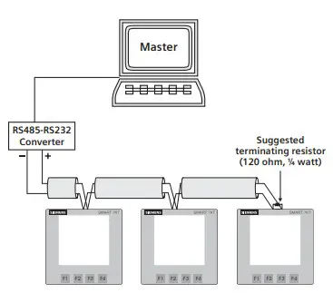
Communication
Protocol and interface
- Protocol: Modbus RTU
- Interface: Integrated RS485 interface
Communication parameters
| Communication address | 1 to 255 |
| Transmission mode | Half duplex |
| Data types | Float and Integer |
| Transmission distance | 500m maximum |
| Transmission Speed | 300, 600, 1200, 2400, 4800, 9600, 19200 (in bps) |
| Parity | None, Odd, Even |
| Stop bits | 1 or 2 |
| Response Time | 100ms Max & Independent, at Baud rate |
Connection diagram for communication
Contact sales for PC based monitoring software to communicate with the meters.
Modbus register addresses list
Readable Parameters: [Length (Register): 2; Data Structure: Float]
| Address | Hex Address | Parameter | Address | Hex Address | Parameter | |
| 30000 | 0x00 | Voltage V1N | 30038 | 0x26 | kVAr2 | |
| 30002 | 0x02 | Voltage V2N | 30040 | 0x28 | kVAr3 | |
| 30004 | 0x04 | Voltage V3N | 30042 | 0x2A | Total KW | |
| 30006 | 0x06 | Average Voltage LN | 30044 | 0x2C | Total KVA | |
| 30008 | 0x08 | Voltage V12 | 30046 | 0x2E | Total KVAr | |
| 30010 | 0x0A | Voltage V23 | 30048 | 0x30 | PF1 | |
| 30012 | 0x0C | Voltage V31 | 30050 | 0x32 | PF2 | |
| 30014 | 0x0E | Average Voltage LL | 30052 | 0x34 | PF3 | |
| 30016 | 0x10 | Current I1 | 30054 | 0x36 | Average PF | |
| 30018 | 0x12 | Current I2 | 30056 | 0x38 | Frequency | |
| 30020 | 0x14 | Current I3 | 30058 | 0x3A | Total net kWh | |
| 30022 | 0x16 | Average Current | 30060 | 0x3C | Total net kVAh | |
| 30024 | 0x18 | kW1 | 30062 | 0x3E | Total net kVArh | |
| 30026 | 0x1A | kW2 | 30064 | 0x40 | kW Max Active Power | |
| 30028 | 0x1C | kW3 | 30066 | 0x42 | kW Min Active Power | |
| 30030 | 0x1E | kVA1 | 30068 | 0x44 | kVAr Max Reactive Power | |
| 30032 | 0x20 | kVA2 | 30070 | 0x46 | kVAr Min Reactive Power | |
| 30034 | 0x22 | kVA3 | 30072 | 0x48 | kVA Max Apparent Power | |
| 30036 | 0x24 | kVAr1 | 30084 | 0x54 | kWh1 (Imp) |
| Address | Hex Address | Parameter | Address | Hex Address | Parameter | |
| 30086 | 0x56 | kWh2 (Imp) | 30193 | 0C1 | 27th Harmonic of V1N | |
| 30088 | 0x58 | kWh3 (Imp) | 30195 | 0C3 | 28th Harmonic of V1N | |
| 30090 | 0x5A | kWh1 (Exp) | 30197 | 0C5 | 29th Harmonic of V1N | |
| 30092 | 0x5C | kWh2 (Exp) | 30199 | 0C7 | 30th Harmonic of V1N | |
| 30094 | 0x5E | kWh3 (Exp) | 30201 | 0C9 | 31st Harmonic of V1N | |
| 30096 | 0x60 | Total kWh (Imp) | 30203 | 0CB | 2nd Harmonic of V2N | |
| 30098 | 0x62 | Total kWh (Exp) | 30205 | 0CD | 3rd Harmonic of V2N | |
| 30100 | 0x64 | kVArh1 (Imp) | 30207 | 0CF | 4th Harmonic of V2N | |
| 30102 | 0x66 | kVArh2 (Imp) | 30209 | 0D1 | 5th Harmonic of V2N | |
| 30104 | 0x68 | kVArh3 (Imp) | 30211 | 0D3 | 6th Harmonic of V2N | |
| 30106 | 0x6A | kVArh1 (Exp) | 30213 | 0D5 | 7th Harmonic of V2N | |
| 30108 | 0x6C | kVArh2 (Exp) | 30215 | 0D7 | 8th Harmonic of V2N | |
| 30110 | 0x6E | kVArh3 (Exp) | 30217 | 0D9 | 9th Harmonic of V2N | |
| 30112 | 0x70 | Total kVArh (Imp) | 30219 | 0DB | 10th Harmonic of V2N | |
| 30114 | 0x72 | Total kVArh (Exp) | 30221 | 0DD | 11th Harmonic of V2N | |
| 30122 | 0x7A | Neutral Current | 30223 | 0DF | 12th Harmonic of V2N | |
| 30124 | 0x7C | THD of 1st Phase Voltage | 30225 | 0E1 | 13th Harmonic of V2N | |
| 30126 | 0x7E | THD of 2nd Phase Voltage | 30227 | 0E3 | 14th Harmonic of V2N | |
| 30128 | 0x80 | THD of 3rd Phase Voltage | 30229 | 0E5 | 15th Harmonic of V2N | |
| 30130 | 0x82 | THD of Voltage V12 | 30231 | 0E7 | 16th Harmonic of V2N | |
| 30132 | 0x84 | THD of Voltage V23 | 30233 | 0E9 | 17th Harmonic of V2N | |
| 30134 | 0x86 | THD of Voltage V13 | 30235 | 0EB | 18th Harmonic of V2N | |
| 30136 | 0x88 | THD of Current I1 | 30237 | 0ED | 19th Harmonic of V2N | |
| 30138 | 0x8A | THD of Current I2 | 30239 | 0EF | 20th Harmonic of V2N | |
| 30140 | 0x8C | THD of Current I3 | 30241 | 0F1 | 21st Harmonic of V2N | |
| 30143 | 08F | 2nd Harmonic of V1N | 30243 | 0F3 | 22nd Harmonic of V2N | |
| 30145 | 091 | 3rd Harmonic of V1N | 30245 | 0F5 | 23rd Harmonic of V2N | |
| 30147 | 093 | 4th Harmonic of V1N | 30247 | 0F7 | 24th Harmonic of V2N | |
| 30149 | 095 | 5th Harmonic of V1N | 30249 | 0F9 | 25th Harmonic of V2N | |
| 30151 | 097 | 6th Harmonic of V1N | 30251 | 0FB | 26th Harmonic of V2N | |
| 30153 | 099 | 7th Harmonic of V1N | 30253 | 0FD | 27th Harmonic of V2N | |
| 30155 | 09B | 8th Harmonic of V1N | 30255 | 0FF | 28th Harmonic of V2N | |
| 30157 | 09D | 9th Harmonic of V1N | 30257 | 101 | 29th Harmonic of V2N | |
| 30159 | 09F | 10th Harmonic of V1N | 30259 | 103 | 30th Harmonic of V2N | |
| 30161 | 0A1 | 11th Harmonic of V1N | 30261 | 105 | 31st Harmonic of V2N | |
| 30163 | 0A3 | 12th Harmonic of V1N | 30263 | 107 | 2nd Harmonic of V3N | |
| 30165 | 0A5 | 13th Harmonic of V1N | 30265 | 109 | 3rd Harmonic of V3N | |
| 30167 | 0A7 | 14th Harmonic of V1N | 30267 | 10B | 4th Harmonic of V3N | |
| 30169 | 0A9 | 15th Harmonic of V1N | 30269 | 10D | 5th Harmonic of V3N | |
| 30171 | 0AB | 16th Harmonic of V1N | 30271 | 10F | 6th Harmonic of V3N | |
| 30173 | 0AD | 17th Harmonic of V1N | 30273 | 111 | 7th Harmonic of V3N | |
| 30175 | 0AF | 18th Harmonic of V1N | 30275 | 113 | 8th Harmonic of V3N | |
| 30177 | 0B1 | 19th Harmonic of V1N | 30277 | 115 | 9th Harmonic of V3N | |
| 30179 | 0B3 | 20th Harmonic of V1N | 30279 | 117 | 10th Harmonic of V3N | |
| 30181 | 0B5 | 21st Harmonic of V1N | 30281 | 119 | 11th Harmonic of V3N | |
| 30183 | 0B7 | 22nd Harmonic of V1N | 30283 | 11B | 12th Harmonic of V3N | |
| 30185 | 0B9 | 23rd Harmonic of V1N | 30285 | 11D | 13th Harmonic of V3N | |
| 30187 | 0BB | 24th Harmonic of V1N | 30287 | 11F | 14th Harmonic of V3N | |
| 30189 | 0BD | 25th Harmonic of V1N | 30289 | 121 | 15th Harmonic of V3N | |
| 30191 | 0BF | 26th Harmonic of V1N | 30291 | 123 | 16th Harmonic of V3N | |
| Address | Hex Address | Parameter | Address | Hex Address | Parameter | |
| 30293 | 125 | 17th Harmonic of V3N | 30393 | 189 | 7th Harmonic of V23 | |
| 30295 | 127 | 18th Harmonic of V3N | 30395 | 18B | 8th Harmonic of V23 | |
| 30297 | 129 | 19th Harmonic of V3N | 30397 | 18D | 9th Harmonic of V23 | |
| 30299 | 12B | 20th Harmonic of V3N | 30399 | 18F | 10th Harmonic of V23 | |
| 30301 | 12D | 21st Harmonic of V3N | 30401 | 191 | 11th Harmonic of V23 | |
| 30303 | 12F | 22nd Harmonic of V3N | 30403 | 193 | 12th Harmonic of V23 | |
| 30305 | 131 | 23rd Harmonic of V3N | 30405 | 195 | 13th Harmonic of V23 | |
| 30307 | 133 | 24th Harmonic of V3N | 30407 | 197 | 14th Harmonic of V23 | |
| 30309 | 135 | 25th Harmonic of V3N | 30409 | 199 | 15th Harmonic of V23 | |
| 30311 | 137 | 26th Harmonic of V3N | 30411 | 19B | 16th Harmonic of V23 | |
| 30313 | 139 | 27th Harmonic of V3N | 30413 | 19D | 17th Harmonic of V23 | |
| 30315 | 13B | 28th Harmonic of V3N | 30415 | 19F | 18th Harmonic of V23 | |
| 30317 | 13D | 29th Harmonic of V3N | 30417 | 1A1 | 19th Harmonic of V23 | |
| 30319 | 13F | 30th Harmonic of V3N | 30419 | 1A3 | 20th Harmonic of V23 | |
| 30321 | 141 | 31st Harmonic of V3N | 30421 | 1A5 | 21st Harmonic of V23 | |
| 30323 | 143 | 2nd Harmonic of V12 | 30423 | 1A7 | 22nd Harmonic of V23 | |
| 30325 | 145 | 3rd Harmonic of V12 | 30425 | 1A9 | 23rd Harmonic of V23 | |
| 30327 | 147 | 4th Harmonic of V12 | 30427 | 1AB | 24th Harmonic of V23 | |
| 30329 | 149 | 5th Harmonic of V12 | 30429 | 1AD | 25th Harmonic of V23 | |
| 30331 | 14B | 6th Harmonic of V12 | 30431 | 1AF | 26th Harmonic of V23 | |
| 30333 | 14D | 7th Harmonic of V12 | 30433 | 1B1 | 27th Harmonic of V23 | |
| 30335 | 14F | 8th Harmonic of V12 | 30435 | 1B3 | 28th Harmonic of V23 | |
| 30337 | 151 | 9th Harmonic of V12 | 30437 | 1B5 | 29th Harmonic of V23 | |
| 30339 | 153 | 10th Harmonic of V12 | 30439 | 1B7 | 30th Harmonic of V23 | |
| 30341 | 155 | 11th Harmonic of V12 | 30441 | 1B9 | 31st Harmonic of V23 | |
| 30343 | 157 | 12th Harmonic of V12 | 30443 | 1BB | 2nd Harmonic of V31 | |
| 30345 | 159 | 13th Harmonic of V12 | 30445 | 1BD | 3rd Harmonic of V31 | |
| 30347 | 15B | 14th Harmonic of V12 | 30447 | 1BF | 4th Harmonic of V31 | |
| 30349 | 15D | 15th Harmonic of V12 | 30449 | 1C1 | 5th Harmonic of V31 | |
| 30351 | 15F | 16th Harmonic of V12 | 30451 | 1C3 | 6th Harmonic of V31 | |
| 30353 | 161 | 17th Harmonic of V12 | 30453 | 1C5 | 7th Harmonic of V31 | |
| 30355 | 163 | 18th Harmonic of V12 | 30455 | 1C7 | 8th Harmonic of V31 | |
| 30357 | 165 | 19th Harmonic of V12 | 30457 | 1C9 | 9th Harmonic of V31 | |
| 30359 | 167 | 20th Harmonic of V12 | 30459 | 1CB | 10th Harmonic of V31 | |
| 30361 | 169 | 21st Harmonic of V12 | 30461 | 1CD | 11th Harmonic of V31 | |
| 30363 | 16B | 22nd Harmonic of V12 | 30463 | 1CF | 12th Harmonic of V31 | |
| 30365 | 16D | 23rd Harmonic of V12 | 30465 | 1D1 | 13th Harmonic of V31 | |
| 30367 | 16F | 24th Harmonic of V12 | 30467 | 1D3 | 14th Harmonic of V31 | |
| 30369 | 171 | 25th Harmonic of V12 | 30469 | 1D5 | 15th Harmonic of V31 | |
| 30371 | 173 | 26th Harmonic of V12 | 30471 | 1D7 | 16th Harmonic of V31 | |
| 30373 | 175 | 27th Harmonic of V12 | 30473 | 1D9 | 17th Harmonic of V31 | |
| 30375 | 177 | 28th Harmonic of V12 | 30475 | 1DB | 18th Harmonic of V31 | |
| 30377 | 179 | 29th Harmonic of V12 | 30477 | 1DD | 19th Harmonic of V31 | |
| 30379 | 17B | 30th Harmonic of V12 | 30479 | 1DF | 20th Harmonic of V31 | |
| 30381 | 17D | 31st Harmonic of V12 | 30481 | 1E1 | 21st Harmonic of V31 | |
| 30383 | 17F | 2nd Harmonic of V23 | 30483 | 1E3 | 22nd Harmonic of V31 | |
| 30385 | 181 | 3rd Harmonic of V23 | 30485 | 1E5 | 23rd Harmonic of V31 | |
| 30387 | 183 | 4th Harmonic of V23 | 30487 | 1E7 | 24th Harmonic of V31 | |
| 30389 | 185 | 5th Harmonic of V23 | 30489 | 1E9 | 25th Harmonic of V31 | |
| 30391 | 187 | 6th Harmonic of V23 | 30491 | 1EB | 26th Harmonic of V31 | |
| Address | Hex Address | Parameter | Address | Hex Address | Parameter | |
| 30493 | 1ED | 27th Harmonic of V31 | 30593 | 251 | 17th Harmonic of I2 | |
| 30495 | 1EF | 28th Harmonic of V31 | 30595 | 253 | 18th Harmonic of I2 | |
| 30497 | 1F1 | 29th Harmonic of V31 | 30597 | 255 | 19th Harmonic of I2 | |
| 30499 | 1F3 | 30th Harmonic of V31 | 30599 | 257 | 20th Harmonic of I2 | |
| 30501 | 1F5 | 31st Harmonic of V31 | 30601 | 259 | 21st Harmonic of I2 | |
| 30503 | 1F7 | 2nd Harmonic of I1 | 30603 | 25B | 22nd Harmonic of I2 | |
| 30505 | 1F9 | 3rd Harmonic of I1 | 30605 | 25D | 23rd Harmonic of I2 | |
| 30507 | 1FB | 4th Harmonic of I1 | 30607 | 25F | 24th Harmonic of I2 | |
| 30509 | 1FD | 5th Harmonic of I1 | 30609 | 261 | 25th Harmonic of I2 | |
| 30511 | 1FF | 6th Harmonic of I1 | 30611 | 263 | 26th Harmonic of I2 | |
| 30513 | 201 | 7th Harmonic of I1 | 30613 | 265 | 27th Harmonic of I2 | |
| 30515 | 203 | 8th Harmonic of I1 | 30615 | 267 | 28th Harmonic of I2 | |
| 30517 | 205 | 9th Harmonic of I1 | 30617 | 269 | 29th Harmonic of I2 | |
| 30519 | 207 | 10th Harmonic of I1 | 30619 | 26B | 30th Harmonic of I2 | |
| 30521 | 209 | 11th Harmonic of I1 | 30621 | 26D | 31st Harmonic of I2 | |
| 30523 | 20B | 12th Harmonic of I1 | 30623 | 26F | 2nd Harmonic of I3 | |
| 30525 | 20D | 13th Harmonic of I1 | 30625 | 271 | 3rd Harmonic of I3 | |
| 30527 | 20F | 14th Harmonic of I1 | 30627 | 273 | 4th Harmonic of I3 | |
| 30529 | 211 | 15th Harmonic of I1 | 30629 | 275 | 5th Harmonic of I3 | |
| 30531 | 213 | 16th Harmonic of I1 | 30631 | 277 | 6th Harmonic of I3 | |
| 30533 | 215 | 17th Harmonic of I1 | 30633 | 279 | 7th Harmonic of I3 | |
| 30535 | 217 | 18th Harmonic of I1 | 30635 | 27B | 8th Harmonic of I3 | |
| 30537 | 219 | 19th Harmonic of I1 | 30637 | 27D | 9th Harmonic of I3 | |
| 30539 | 21B | 20th Harmonic of I1 | 30639 | 27F | 10th Harmonic of I3 | |
| 30541 | 21D | 21st Harmonic of I1 | 30641 | 281 | 11th Harmonic of I3 | |
| 30543 | 21F | 22nd Harmonic of I1 | 30643 | 283 | 12th Harmonic of I3 | |
| 30545 | 221 | 23rd Harmonic of I1 | 30645 | 285 | 13th Harmonic of I3 | |
| 30547 | 223 | 24th Harmonic of I1 | 30647 | 287 | 14th Harmonic of I3 | |
| 30549 | 225 | 25th Harmonic of I1 | 30649 | 289 | 15th Harmonic of I3 | |
| 30551 | 227 | 26th Harmonic of I1 | 30651 | 28B | 16th Harmonic of I3 | |
| 30553 | 229 | 27th Harmonic of I1 | 30653 | 28D | 17th Harmonic of I3 | |
| 30555 | 22B | 28th Harmonic of I1 | 30655 | 28F | 18th Harmonic of I3 | |
| 30557 | 22D | 29th Harmonic of I1 | 30657 | 291 | 19th Harmonic of I3 | |
| 30559 | 22F | 30th Harmonic of I1 | 30659 | 293 | 20th Harmonic of I3 | |
| 30561 | 231 | 31st Harmonic of I1 | 30661 | 295 | 21st Harmonic of I3 | |
| 30563 | 233 | 2nd Harmonic of I2 | 30663 | 297 | 22nd Harmonic of I3 | |
| 30565 | 235 | 3rd Harmonic of I2 | 30665 | 299 | 23rd Harmonic of I3 | |
| 30567 | 237 | 4th Harmonic of I2 | 30667 | 29B | 24th Harmonic of I3 | |
| 30569 | 239 | 5th Harmonic of I2 | 30669 | 29D | 25th Harmonic of I3 | |
| 30571 | 23B | 6th Harmonic of I2 | 30671 | 29F | 26th Harmonic of I3 | |
| 30573 | 23D | 7th Harmonic of I2 | 30673 | 2A1 | 27th Harmonic of I3 | |
| 30575 | 23F | 8th Harmonic of I2 | 30675 | 2A3 | 28th Harmonic of I3 | |
| 30577 | 241 | 9th Harmonic of I2 | 30677 | 2A5 | 29th Harmonic of I3 | |
| 30579 | 243 | 10th Harmonic of I2 | 30679 | 2A7 | 30th Harmonic of I3 | |
| 30581 | 245 | 11th Harmonic of I2 | 30681 | 2A9 | 31st Harmonic of I3 | |
| 30583 | 247 | 12th Harmonic of I2 | ||||
| 30585 | 249 | 13th Harmonic of I2 | ||||
| 30587 | 24B | 14th Harmonic of I2 | ||||
| 30589 | 24D | 15th Harmonic of I2 | ||||
| 30591 | 24F | 16th Harmonic of I2 | ||||
Readable / writable parameters: [Data Structure: Integer]
| Address | Hex Address | Parameter | Range | Length (Register) | |
| 40000 | 0x00 | Password | Min value: 0 | Max value: 9998 | 1 |
| 40001 | 0x01 | N/W Selection | Value: 0 | Meaning: 3P4W | 1 |
| Value: 1 | Meaning: 3P3W | 1 | |||
| Value: 2 | Meaning: 1P2W-P1 | 1 | |||
| Value: 3 | Meaning: 1P2W-P2 | 1 | |||
| Value: 4 | Meaning: 1P2W-P3 | 1 | |||
| 40002 | 0x02 | CT Secondary | Min value: 1 | Max value: 5 | 1 |
| 40003 | 0x03 | CT primary (CT Secondary=5)(A) | Min value: 5 | Max value: 10000 | 1 |
| CT primary (CT Secondary=1)(A) | Min value: 1 | Max value: 10000 | |||
| 40004 | 0x04 | PT Secondary | Min value: 100 | Max value: 500 | 1 |
| 40006 | 0x06 | PT primary | Min value: 100 | Max value: 500kV | 2 |
| 40007 | 0x07 | Slave id | Min value: 1 | Max value: 255 | 1 |
| 40008 | 0x08 | Baud rate | Value: 0x0000 | Meaning: 300 | 1 |
| Value: 0x0001 | Meaning: 600 | ||||
| Value: 0x0002 | Meaning: 1200 | ||||
| Value: 0x0003 | Meaning: 2400 | ||||
| Value: 0x0004 | Meaning: 4800 | ||||
| Value: 0x0005 | Meaning: 9600 | ||||
| Value: 0x0006 | Meaning: 19200 | ||||
| 40009 | 0x09 | Parity | Value: 0x0000 | Meaning: None | 1 |
| Value: 0x0001 | Meaning: Odd | ||||
| Value: 0x0002 | Meaning: Even | ||||
| 40010 | 0x0A | Stop bit | Value: 0x0000 | Meaning: 1 | 1 |
| Value: 0x0001 | Meaning: 2 | 1 | |||
| 40011 | 0x0B | Backlight OFF | Min Value: 0 | Max Value: 7200 | 1 |
| 40012 | 0x0C | Factory Default | Value: 1 | Meaning: Set to factory setting range | 1 |
| 40016 | 0x10 | Auto Mode Pages | Min Value: 1 | Max Value: 22 | |
| Page No | Meaning | ||||
| 40017 | 0x11 | Page Address Sequence | 1-22 | 1-First Page; 22-Last Page | 1 |
| 40018 | 0x12 | Page Address Sequence | 1-22 | 1-First Page; 22-Last Page | 1 |
| 40019 | 0x13 | Page Address Sequence | 1-22 | 1-First Page; 22-Last Page | 1 |
| 40020 | 0x14 | Page Address Sequence | 1-22 | 1-First Page; 22-Last Page | 1 |
| 40021 | 0x15 | Page Address Sequence | 1-22 | 1-First Page; 22-Last Page | 1 |
| 40022 | 0x16 | Page Address Sequence | 1-22 | 1-First Page; 22-Last Page | 1 |
| 40023 | 0x17 | Page Address Sequence | 1-22 | 1-First Page; 22-Last Page | 1 |
| 40024 | 0x18 | Page Address Sequence | 1-22 | 1-First Page; 22-Last Page | 1 |
| 40025 | 0x19 | Page Address Sequence | 1-22 | 1-First Page; 22-Last Page | 1 |
| 40026 | 0x1A | Page Address Sequence | 1-22 | 1-First Page; 22-Last Page | 1 |
| 40027 | 0x1B | Page Address Sequence | 1-22 | 1-First Page; 22-Last Page | 1 |
| 40028 | 0x1C | Page Address Sequence | 1-22 | 1-First Page; 22-Last Page | 1 |
| 40029 | 0x1D | Page Address Sequence | 1-22 | 1-First Page; 22-Last Page | 1 |
| 40030 | 0x1E | Page Address Sequence | 1-22 | 1-First Page; 22-Last Page | 1 |
| 40031 | 0x1F | Page Address Sequence | 1-22 | 1-First Page; 22-Last Page | 1 |
| 40032 | 0x20 | Page Address Sequence | 1-22 | 1-First Page; 22-Last Page | 1 |
| 40033 | 0x21 | Page Address Sequence | 1-22 | 1-First Page; 22-Last Page | 1 |
| 40054 | 0x36 | Page Address Sequence | 1-22 | 1-First Page; 22-Last Page | 1 |
| 40055 | 0x37 | Page Address Sequence | 1-22 | 1-First Page; 22-Last Page | 1 |
| 40059 | 0x3B | Page Address Sequence | 1-22 | 1-First Page; 22-Last Page | 1 |
| 40060 | 0x3C | Page Address Sequence | 1-22 | 1-First Page; 22-Last Page | 1 |
| 40061 | 0x3D | Page Address Sequence | 1-22 | 1-First Page; 22-Last Page | 1 |
| 40034 | 0x22 | Demand Interval Method | Value: 0x0000 | Meaning: Sliding | 1 |
| Value: 0x0001 | Meaning: Fixed | 1 | |||
| 40035 | 0x23 | Demand Interval Duration | MIN Value: 1 | MAX Value: 30 | 1 |
| 40036 | 0x24 | Demand Interval Length | MIN Value: 1 | MAX Value: 30 | 1 |
| 40043 | 0x2B | Reset Max | Value: 1 | Meaning: Reset all Max power | 1 |
| 40044 | 0x2C | Reset Energy | Value: 1 | Meaning: Reset all energyto factory setting range | 1 |
| 40046 | 0x2E | Reset ON Hour | Value: 1 | Meaning: Reset ON hour | 1 |
Maintenance
Guidelines
- The equipment should be cleaned regularly to avoid blockage of ventilating parts.
- Clean the equipment with a clean dry or damp cloth. Do not use any cleaning agent other than water.
Disposal and recycling Dispose of or recycle the module in accordance with the applicable laws and regulations in your country.


