Tchibo 8300 Greenhouse Instruction Manual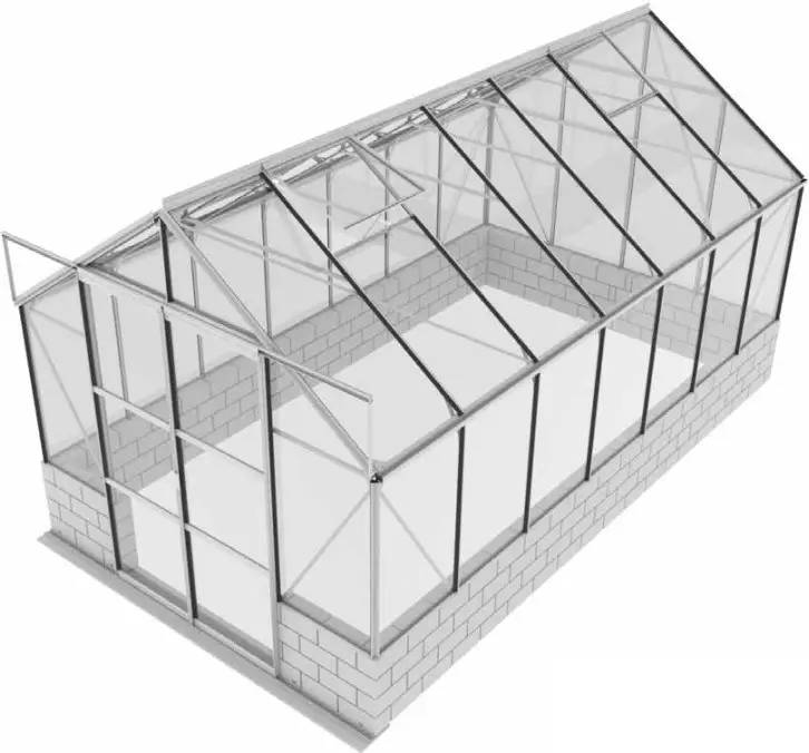
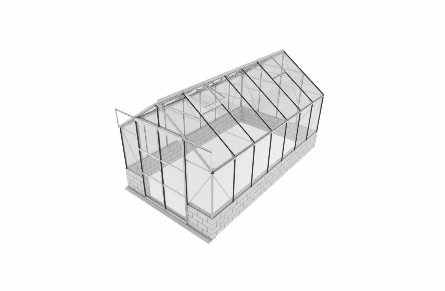
CASSANDRA SIOLA COMBI STONE WALL.
Note: The stones delivered to assemble the Cassandra wall are produced to create a natural look. As a result no two stones are identical. In order to compensate for the differences in height that cannot be avoided during production, bricks of approximately the same height should be assembled beforehand for each row.
Wall Assembly
- Prepare a strip foundation for the stone wall. This can be constructed from compacted gravel or poured from concrete. It is important that it is level and large enough for the stones, see dimensions on plan. Please leave the front area free of foundation so that the door runner stones can be positioned and aligned after the wall is assembled.
- Following the plan, arrange the stones in rows as shown to avoid any cross joints. Rows 1, 2 and 3 should simply be placed one on top of the other.
- At the end of each row the final stone must be broken to the correct size.
a. Measure the remaining space to achieve the required dimensions.
b. Mark the stone on all sides.
c. Using a hammer and stone chisel start on 1 side and solidly hammer along the line.
d. Turn the stone 90° and continue to solidly hammer along the line.
e. Continue to turn the stone 90° and hammer until it breaks. - The 4th and final row should be levelled and fixed in place using supplied glue.
Assembly – Door runner stones
- The door runner stones (Türlauf) can be assembled upright or flat.
- Prepare a strip foundation at the necessary depth and position the door runner stones so that the total length is 2550 mm. The top edge of the door runner stones must be 500mm below the top edge of the wall and they should be in contact with the wall stones.
- Fix the door runner stones with mortar and fill around with earth.
| Item No. | Part | Sect. Ref. | Size mm | Quantity per | ||
| 8300 | 9900 | 11500 | ||||
| 1001 |  | 1 – 6 | M6 x 12 | 238x | 255x | 273x |
| 1002 |  | 1 – 6 | M6 | 241x | 258x | 276x |
| 1003 | 5 | 3.5 x 16 | 32x | 32x | 32x | |
| 1006 |  | 6 | 3.5 x 6 | 24x | 24x | 24x |
| 1007 |  | 5 | M4 | 4x | 4x | 4x |
| 1009 |  | 5 | Ø8/4 | 4x | 4x | 4x |
| 1014 |  | 5 | 20 | 4x | 4x | 4x |
| 1015 |  | 5 | Ø22 | 4x | 4x | 4x |
| 1017 |  | 4B | 46 | 4x | 4x | 4x |
| 1018 |  | 4B | 43.7 | 8x | 8x | 8x |
| 1019 | | 6 | 15 | 4x | 4x | 4x |
| 1020 |  | 7 | 105000115000125000 | 1x– | -1x- | –1x |
| 1043 | 23 | 170 | 4x | 4x | 4x | |
| 1063 |  | 6 | 635 | 4x | 4x | 4x |
| 1064 |  | 6 | 602 | 4x | 4x | 4x |
| 1065 | 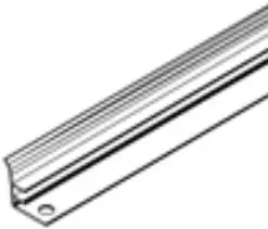 | 6 | 520 | 8x | 8x | 8x |
| 1066 | 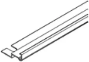 | 6 | 602 | 4x | 4x | 4x |
| 1067 | 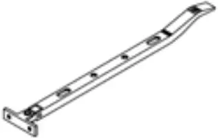 | 6 | 295 | 4x | 4x | 4x |
| 1092 | 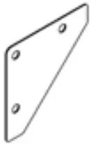 | 14A | 120 | 12x | 12x | 12x |
| 1304 |  | 5 | M4 x 18 | 4x | 4x | 4x |
| 1310 |  | 4A | 30.4 | 2x | 2x | 2x |
| 1325 |  | 1 | 3106 | 2x | – | – |
| 1326 | | 1 | 3728 | – | 2x | – |
| 1347 |  | 3 | 1257 | 2x | 2x | 2x |
| 1359 |  | 5 | 621 | 2x | 2x | 2x |
| 1360 |  | 5 | 621 | 2x | 2x | 2x |
| 1361 |  | 5 | 621 | 4x | 4x | 4x |
| 1362 |  | 5 | 613 | 2x | 2x | 2x |
| 1500 |  | 5 | M6 x 5 | 2x | 2x | 2x |
| 1515 |  | 5 | M6 | 2x | 2x | 2x |
| 2001 |  | 5L | M6 x 12 | 1x | 1x | 1x |
| 2005 |  | 5R | 100 | 1x | 1x | 1x |
| 2006 |  | 5R | 10 | 2x | 2x | 2x |
| 2016 |  | 6 | 40 | 8x | 8x | 8x |
| 2021 |  | 5 | 1923 | 2x | 2x | 2x |
| 2028 |  | 1 | 3106 | 2x | – | – |
| 2029 | | 1 | 3728 | – | 2x | – |
| 2030 | | 1 | 4350 | – | – | 2x |
| 2033 |  | 4B | 1898 | 4x | 4x | 4x |
| 2035 |  | 2 | 2476 | 1x | 1x | 1x |
| 2039 | | 23 | 1535 | 2x | 2x | 2x |
| 2040 |  | 23 | 1535 | 2x | 2x | 2x |
| 2043 |  | 4A | 416 | 2x | 2x | 2x |
| 2048 |  | 3 | 1318 | 1x | 1x | 1x |
| 2051 |  | 4A | 3106 | 1x | – | – |
| 2052 | | 4A | 3728 | – | 1x | – |
| 2053 | | 4A | 4350 | – | – | 1x |
| 2054 |  | 2 | 1318 | 1x | 1x | 1x |
| 2055 |  | 4B | 1511 | 8x | 10x | 12x |
| 2056 |  | 1 | 255 | 8x | 10x | 12x |
| 2057 |  | 4B | 1184 | 4x | 5x | 6x |
| 2058 |  | 5 | 1923 | 2x | 2x | 2x |
| 2059 |  | 4B | 30 | 4x | 4x | 4x |
| 2060 |  | 3 | 633 | 1x | 1x | 1x |
| 2061 |  | 3 | 633 | 1x | 1x | 1x |
| 2066 |  | 23 | 1023 | 4x | 4x | 4x |
| 2067 |  | 23 | 1475 | 2x | 2x | 2x |
| 2068 |  | 23 | 1475 | 2x | 2x | 2x |
| 2069 |  | 123 | 1137 | 8x | 8x | 8x |
| 2070 |  | 4B | 2544 | 1x | 1x | 1x |
| 2071 |  | 2 | 1475 | 1x | 1x | 1x |
| 2072 | | 1 | 1023 | 8x | 10x | 12x |
| 2073 |  | 2 | 2484 | 1x | 1x | 1x |
| 2074 | | 1 | 4350 | – | – | 2x |
| 2091 |  | 23 | 175 | 2x | 2x | 2x |
| 2092 |  | 123 | 37 | 8x | 8x | 8x |
| 2094 |  | 3 | 426 | 1x | 1x | 1x |
| 2096 |  | 3 | 619 | 2x | 2x | 2x |
| 2098 |  | 5L | 1923 | 1x | 1x | 1x |
| 2099 |  | 5R | 1923 | 1x | 1x | 1x |
| 2100 |  | 23 | 425 | 2x | 2x | 2x |
| 4201 |  | 4A | M6 x 45 | 2x | 2x | 2x |
| 5001 |  | 3 | 33 | 1x | 1x | 1x |
| 5002 |  | 3 | 33 | 1x | 1x | 1x |
| 6060 |  | 4A | Ø12/6 | 2x | 2x | 2x |
| 9104 |  | 4B | 19 | 17x | 19x | 21x |
| 6602 |  | 7 | 1509 | 16x | 20x | 24x |
| 6603 | | 7 | 970 | 8x | 8x | 8x |
| 6605 | | 7 | 610 | 8x | 8x | 8x |
| 6606 | | 7 | 588 | 4x | 4x | 4x |
| 6607 | | 7 | 425 | 4x | 4x | 4x |
| 6612 | | 7 | 1021 | 24x | 28x | 32x |
| 6613 | | 7 | 1472 | 8x | 8x | 8x |
Safety Warning
- PLEASE READ THESE INSTRUCTIONS CAREFULLY AND COMPLETELY BEFORE ASSEMBLING YOUR GREENHOUSE.
- Sharp edges and corners can cause injury. Always wear protective glasses, gloves, shoes and headgear when handling the aluminium profiles, glass and polycarbonate sheets. Broken glass is a safety hazard – always clear up immediately and dispose of with care.
- The product you have purchased is intended only for growing plants and should only be used for this purpose. When used for other purposes we will take no responsibility.
- It is recommended that this greenhouse is assembled by two people.
- Should you encounter difficulties constructing this house, or in fitting the glass or polycarbonate sheets, please contact your retailer – do not use force!
- The greenhouse must always be anchored.
Assembly Instructions
Site Selection
Always try to select a sunny location, sheltered from the wind as much as possible.
Important
Before assembling your new greenhouse, please check that all parts in the provided list are included. Please take each bundle out of the packaging in order to identify the parts better. It is important that the opened bundles do not get mixed with one another. If something is missing please contact your retailer. Nuts (1002) – Max. tightening torque 3Nm
Necessary Tools
Screw drivers (Normal and Crosshead PH2), 10 mm socket spanner or wrench, 10 mm combination spanner, knife, measuring stick, spirit level, Accu-drill with adjustable torque.
Maintenance
The greenhouse should be thoroughly washed with a gentle detergent occasionally. Please check that the detergent used does not react aggressively with aluminium or the glass fixing clips. Ensure that the upper and lower door tracks are cleaned regularly to avoid a build-up of debris.
0A. Base
Important! The base must be exactly square and level. Foundations must extend down below the frost level. The front must allow room on the foundation, minimum 70mm, for the support of the door guide (2070) in section 4B.
0B. Wall
Build a wall 500mm high on the prepared foundation as shown, with an opening of 1218mm in the front. The front must allow room on the foundation,minimum 70mm, for the support of the door guide (2070) in section 4B. Important! The wall must be exactly square and level.
(Attention! Only when the greenhouse has to be located in a very windy and unprotected location: Drill through the profiles at the base of the greenhouse and connect them to the top of the wall. Screws and wall plugs are notincluded.)
Side Elements
Lay all of the parts on the floor and connect them loosely. At this stage it is necessary with each vertical aluminium bar (2072) to include an extra connecting bolt, to connect corner braces (2056) (1.4). Loosely connect the corner plate (1092) (1.1). In step 4 the corner plate bolts must also be connected to the Gable ends.
plain Gable end
Lay all of the parts on the floor and connect them loosely. Include one extra connecting bolt in the vertical bars (2067, 2068 and 2071) to connect the cross braces (2.2).
Door Gable end
Lay all of the parts on the floor and connect them loosely. The door runner bars (1347) will be connected to the horizontal bar (2048). Connect each of these loosely from the outside with three bolts and two nuts. Connect (5001) and (5002) as shown in (3.9) (3.10) with a nut. As in step 2, please include one extra bolt in both vertical bars (2067) and (2068) (3.3).
Connecting the separate Elements
Bolt the side elements to the end elements (4.1) & (4.2). Loosely connect the corner plate (1092) above the eaves (4.3). Assemble the ridge bar and then the corner plates (1092) on the Gable ends (4.4/4.5). Connect the door runner supports (2043) to the door runner bars (1347) using washer (6060) (4.1) and to the Gable end using bolt (4201) and spacer (1310) (4.3) (4.6)
Connecting the separate Elements
Lift the assembled structure onto the prepared wall and connect loosely using clips (9104) (4.9). Screws and wall plugs are not included. Loosely connect the door runner bar (2070) to the front of the wall (4.7) (4.8) using the 4 holders (2059) and countersunk screws (not included). Connect the roof glazing bars (2055) betweenthe eaves (4.10) and the ridge bar (4.11). Insert extra bolts into each glazing bar depending on which house you have bought. The number is indicated in a circle on each bar and to be read beginning from both ends.
5 L and 5R. Doors
Attention: Do not stand the assembled doors on the door gliders (1014) to avoid damaging them. Push the door gliders (1014) onto both ends of door bar (1360) (5.1). Assemble the doors as shown in diagram 5. Bolt door bar (1362) to upper bar (1359) (5.3) and slide door seals (2021) into door bars (2058) (5.5). Slide bolts (1500) into the bottom of the bolt channel holding brush seals (2021) and fix it in place using nut (1515) (5.6). Cut the door seals (2021) to length. Please ensure that for the inside side bar the part (2098) is used on the left in (5L) and (2099) on the right in (5R). Connect door rollers (1015) to the door bar (1362) using bolt (1304), washer (1009) and nut (1007) (5.4).Connect bolt (2001) at the join between both (1347) as shown (5R). Loosen the door supports (2043). Now slide the door rollers into the door runner bar (1347) (5.7). Please ensure that the door gliders are also running on the bottom track (5.8). Adjust the doors so that they move freely
Roof vents
Connect the side bars (1065) and the top bar (1064) depending on the pane thickness. Up to 4 mm, see (6.1). For 4 mm and over, see (6.2). Place the bolts to connect the bottom bar (1066) in the prepared holes, and then slide the glass into the tracks in side bars (1065) (6.3).Now connect bottom bar (1066), and ensure that the window is totally square before tightening all bolts. Position the window in the ridge bar from one end (6.4) and (6.5) and slide it to the required position (6.6). Connect the window sill (1063) with the extra bolts in the roof bars (6.7). Connect the window opener (1067) to the bottom bar (1066) using screws (1006) (6.8)
Glazing – Clear Glass
Please note the already mentioned safety precautions. Press the glazing seals (1020) onto the aluminium profiles (7.1) and cut to length. Begin on the roof by positioning the glass in place and fixing it by pushing the glazing list into position at the side (7.1). Cut each list to the length of the glass pane. Continue to fix the glass panes into the sides and doors cutting the glazing list to match the glass pane.
Finishing
If desired, it is possible to seal the greenhouse at the edges using neutral silicone. Silicone is not included. Place the warning label inside the house. A full range of accessories is available to help you make the most of this product. Please contact your local stockist for details.
Safety Notice
In the event of high winds, close all doors and vents. In the event of heavy snowfall, clear the roof of the building or take suitable measures to support the roof. Heat the building in winter.
Comments
For the complete protection of your new greenhouse, we advise you to include it in your house insurance. Please take note of possible building rules relating to the position – ing of greenhouses. Please stick the greenhouse model label pro – vided onto the door bar (1362) after successfully assembling this product. This information is important in the event that replacement parts are later required. Please keep these Assembly Instructions in a safe place, for future reference! Our policy is one of continuous improvement and we reserve the right to change the specifications without prior notice.


