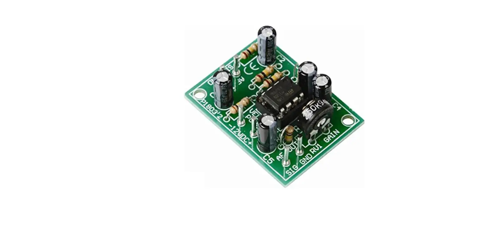
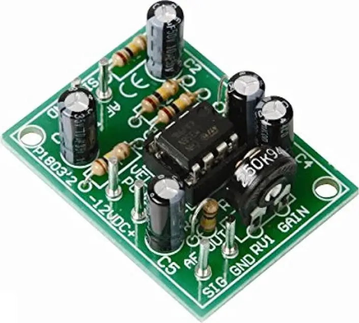
velleman K1803 Universal Mono Preamplifier
This kit has been developed as a pre-module for a number of audio applications where there is insufficient input signal. Applications as a microphone pre-amplifier or for level correction.
Specifications
- Power supply: 10-30VDC / 10mA.
- Output impedance: 1Kohm.
- Adjustable output level: max. 40dB.
- Frequency range: 20Hz to 20kHz ± 3dB.
- Max. input signal: 40mV.
- PCB dimensions: 30 x 40mm (1.2″ x 1.57″).
Assembly
Assembly (Skipping this can lead to troubles ! )
Ok, so we have your attention. These hints will help you to make this project successful. Read them carefully.
Make sure you have the right tools
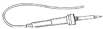
- A good quality soldering iron (25-40W) with a small tip.

- Wipe it often on a wet sponge or cloth, to keep it clean; then apply solder to the tip, to give it a wet look. This is called ‘thinning’ and will protect the tip, and enables you to make good connections. When solder rolls off the tip, it needs cleaning.

- Thin raisin-core solder. Do not use any flux or grease.
- A diagonal cutter to trim excess wires. To avoid injury when cutting excess leads, hold the lead so they cannot fly towards the eyes.

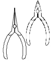
- Needle nose pliers, for bending leads, or to hold components in place.
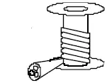
- Small blade and Phillips screwdrivers. A basic range is fine.
 For some projects, a basic multi-meter is required or might be handy
Assembly Hints
- Make sure the skill level matches your experience, to avoid disappointments.
- Follow the instructions carefully. Read and understand the entire step before you perform each operation.
- Perform the assembly in the correct order as stated in this manual
- Position all parts on the PCB (Printed Circuit Board) as shown on the drawings.
- Values on the circuit diagram are subject to changes.
- Values in this assembly guide are correct*
- Use the checkboxes to mark your progress.
- Please read the included information on safety and customer service
Typographical inaccuracies excluded. Always look for possible last-minute manual updates, indicated as ‘NOTE’ on a separate leaflet.
Soldering Hints
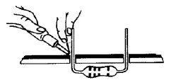
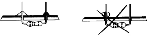
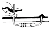
- Mount the component against the PCB surface and carefully solder the leads

- Make sure the solder joints are cone-shaped and shiny

- Trim excess leads as close as possible to the solder joint

- REMOVE THEM FROM THE TAPE ONE AT A TIME !
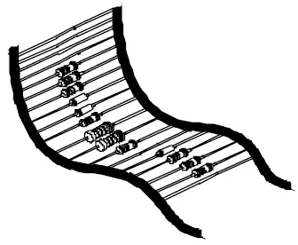 DO NOT BLINDLY FOLLOW THE ORDER OF THE COMPONENTS ONTO THE TAPE. ALWAYS CHECK THEIR VALUE ON THE PARTS LIST!
INSTALLATION INSTRUCTIONS
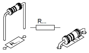
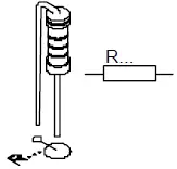
- Resistors

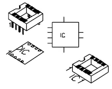
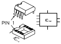
- IC socket, Watch the position of the notch!

- Vertical resistors

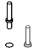
- PCB pins

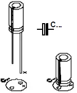
- Electrolytic capacitors. Watch the polarity !

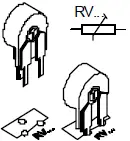
- Trim potentiometer

- IC mounting
Connection
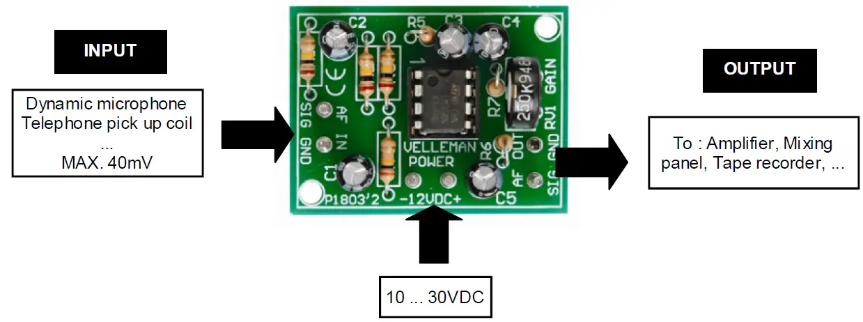
- Connect a stabilized supply between 10 and 30V with the points “+” and “-” on the print.
- The input is connected on the points “AF IN”.
- The output is taken on the connection “AF OUT” and the ground “-”.
- To connect your in– and output you’d better use a screened wire, to avoid interferences and rumble
- With the trimmer RV1 you can control the output signal between 0 and max.
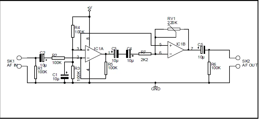
Schematic diagram
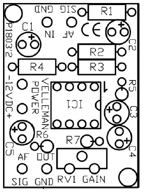
PCB

Modifications and typographical errors reserved © Velleman nv. H1803IP – 2010 – ed.2 VELLEMAN NV Legen Heirweg 33, 9890 Gavere Belgium – Europe
see our website: www.velbus.be.