![]()
D E E P S E A E L E C T R O N I C S
053-265
ISSUE 1
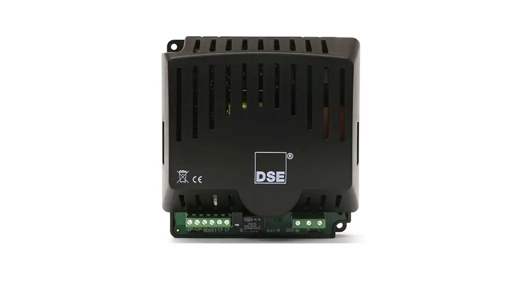
DSE BC2415i Installation Instructions
INSTALLATION
The DSE BC2415i battery charger is designed to be mounted within a control panel, on the panel DIN rail utilising the integral mounts or on a chassis utilising the mounting holes. Dimension and mounting details are given overleaf. The battery charger is designed as a fit-and-forget device therefore, is permanently connected to the supply and the load, with no requirement to disable the charger during heavy load, such as engine cranking, or when in parallel with a charge alternator.
BATTERY SUITABILITY
![]() WARNING!: Do not connect the DSE chargers to non-rechargeable batteries.
WARNING!: Do not connect the DSE chargers to non-rechargeable batteries.![]() WARNING!: Non-sealed Lead Acid batteries must be placed in a well ventilated area.
WARNING!: Non-sealed Lead Acid batteries must be placed in a well ventilated area.![]() NOTE: Typically a 15 A battery charger is suitable for 150 Ah battery when rated at C/10. A 15 A battery charger can be used to charge a battery with a greater than a 150 Ah rating but it will take longer to be fully charged. The DSE Battery Charger’s Current Limit can be reduced through the DSE Configuration Suite PC Software to suit batteries with a less than a 150 Ah rating.
NOTE: Typically a 15 A battery charger is suitable for 150 Ah battery when rated at C/10. A 15 A battery charger can be used to charge a battery with a greater than a 150 Ah rating but it will take longer to be fully charged. The DSE Battery Charger’s Current Limit can be reduced through the DSE Configuration Suite PC Software to suit batteries with a less than a 150 Ah rating.![]() NOTE: For further details of module configuration, refer to DSE Publication: 057-353 DSE BC2415i Configuration Suite PC Software Manual..
NOTE: For further details of module configuration, refer to DSE Publication: 057-353 DSE BC2415i Configuration Suite PC Software Manual..
The battery charger is factory set by DSE to suit Lead Acid batteries. The battery charger can be adjusted to suit many battery types and has the option of fixing the output voltage range and characteristics using the Configuration Suite PC Software.
Care must be taken to ensure the batteries connected to the charger are of the correct technology to suit the setting of the charger.
INDICATIONS
The DSE Battery Charger features LED indicators to show its status.
| Condition | OPE | FAULT1 | FAULT1 |
| Charger Off | Off | Off | Off |
| Bulk Charge in Progress | Yellow Constant | Off | Off |
| Absorption Charge in Progress | Yellow Flashing | Off | Off |
| Float Charge in Progress | Green Constant | Off | Off |
| Storage Charge in Progress | Green Flashing | Off | Off |
| Battery Not Detected | Green Flashing | Red Flashing | Red Flashing |
| Battery Connected | Green Constant | Red Constant | Red Constant |
| Not Charging (Charger is operating correctly but not connect to battery) | Off | Red Constant | Red Constant |
BOOST MODE
![]() NOTE: Comprehensive module configuration is possible using the DSE Configuration Suite PC Software, refer to DSE publication 057-353 DSE BC2415i Configuration Suite PC Software Manual available from www.deepseaelectronics.com.
NOTE: Comprehensive module configuration is possible using the DSE Configuration Suite PC Software, refer to DSE publication 057-353 DSE BC2415i Configuration Suite PC Software Manual available from www.deepseaelectronics.com.
Boost mode is operated automatically or by activation of the digital input (if configured to perform this function). The battery charger output voltage rises to the configured Boost Voltage until the output current falls below the configured Bulk to Adoption Trigger Level.
The battery charger automatically enters Boost Mode again when the battery voltage drops below the configured Bulk Trigger Voltage level.
ABSORPTION MODE
The battery charger enters this mode once the charger’s output current falls below the configured Bulk to Adoption Trigger Level.
In this mode the battery charger load output falls to the configured Absorption Voltage and is maintained there for the duration of the Absorption Timer. During this time, the charge current continues to decrease.
FLOAT MODE
The battery charger enters this mode once the Absorption Timer has expired.
In this mode the battery charger load output falls to the configured Float Voltage to prevent damage to the battery due to excessive gassing. Float Charge is used to provide a small amount of current to the battery to overcome internal losses and keep the battery at its 100% charged state.
STORAGE MODE
NOTE: Storage Stage is not applicable to three stage charging profiles.
The battery charger enters this mode once the Float Timer has expired.
In this mode the battery charger output voltage falls to the configured Storage Voltage to minimise gassing and corrosion of the positive plates. Once a week, the battery charger output voltage is raised back to the Absorption Voltage for the Absorption Timer to equalize the battery cells. This feature prevents stratification of the electrolyte and sulphation, which is a major cause of early battery failure.
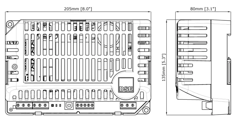
DIMENSIONS AND MOUNTING
| Parameter | Comment |
| Mounting Environment | For use indoors or enclosed spaces only. |
| Overall Size | 205 mm x 135 mm x 80 mm (8.0″ x 5.3″ x 3.1″) |
| Perimeter Distance for Ventalation | 100 mm (3.9 “) |
| Material | Polycarbonate |
| Surface Finish | Black Resin |
| Protection Category | IP20, NEMA 1 |
| Unboxed Weight | 0.78 kg (1.7 lb 27.5 oz) |
| Mounting Type | DIN Rail or Chassis Mounting. Base mounted to a vertical surface with connection terminals to the bottom. |
| DIN Rail Type | EN 50022 35 mm type only |
| Mounting Holes | Suitable for M4 |
| Mounting Hole Centres | 190 mm x 120 mm (7.5″ x 4.7″) |
| Charge Failure Relay Rating | 30 V at 3 A DC |
| Operating Temperature | -30 °C to +50 °C (-22 °F to +122 °F) |
| Operating Temperature (With Derate To Output) | -30 °C to +70 °C (-22 °F to +158 °F) |
TERMINAL SPECIFICATION
| Parameter | Specification |
| Connection Type | PCB mounted Screw terminal, rising clamp, no internal spring. |
| Minimum Cable Size | 0.5 mm2 (AWG 20) |
| Maximum Cable Size | 2.5 mm2 (AWG 13) |
| Tightening Torque | 0.5 Nm (4.5 lb-in) |
| Wire Strip Length | 7 mm (9/32″) |
| DSE BC2415i AC Fuse (230 V AC Supply) | 3.5 A Anti-Surge |
| DSE BC2415i AC Fuse (110 V AC Supply) | 6.3 A Anti-Surge |
| DSE BC2415i DC Output Fuse | 20.0 A Anti-Surge |
![]() DANGER OF DEATH: LIVE PARTS exist within the enclosure. The enclosure cover must not be removed when connected to an AC supply.
DANGER OF DEATH: LIVE PARTS exist within the enclosure. The enclosure cover must not be removed when connected to an AC supply.![]() DANGER OF DEATH: The DSE charger must be mounted in a suitable way, so that access to the exposed terminals is prevented during operation and when connected to the mains supply.
DANGER OF DEATH: The DSE charger must be mounted in a suitable way, so that access to the exposed terminals is prevented during operation and when connected to the mains supply.
TYPICAL WIRING DIAGRAM ![]() NOTE: A larger version of the Typical Wiring Diagram is available in the product’s operator manual, refer to DSE Publication: 057-352 DSE BC2415i Operator Manual available from www.deepseaelectronics.com for more information.
NOTE: A larger version of the Typical Wiring Diagram is available in the product’s operator manual, refer to DSE Publication: 057-352 DSE BC2415i Operator Manual available from www.deepseaelectronics.com for more information. 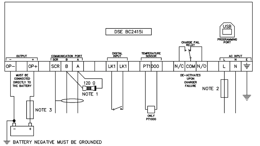
NOTE 1 A 120 OHM TERMINATION RESISTOR MUST BE FITTED IF IT IS THE FIRST OR LAST DEVICE ON THE COMMUNICATIONS LINK
NOTE 2 FUSE APPROPRIATELY WHEN BASED ON CONFIGURED CHARGE CURRENT LIMIT AND AS CLOSE TO THE BATTER CHARGER AS POSSIBLE TO PROTECT THE CABLES
NOTE 3 FUSE APPROPRIATELY AND AS CLOSE TO THE BATTERY AS POSSIBLE TO PROTECT THE CABLES AND BATTERY
Deep Sea Electronics Ltd.
Tel:+44 (0)1723 890099
Email: [email protected]
Web: www.deepseaelectronics.com
Deep Sea Electronics Inc.
Tel: +1 (815) 316 8706
Email: [email protected]
Web: www.deepseaelectronics.com


