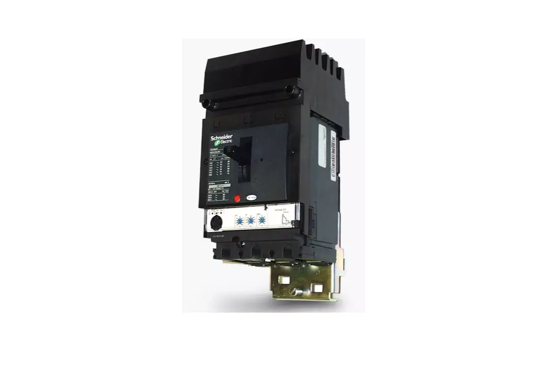
I-Line MCCB Triple Pole Incomer
Product Information: I-Line MCCB
The I-Line MCCB is a type of molded case circuit breaker that is
designed to provide protection against overcurrents and short
circuits. It is commonly used in panel boards and switchboards for
power distribution applications. The product is manufactured by
Schneider Electric Limited, a global company that specializes in
energy management and automation solutions.
The I-Line MCCB comes in different sizes and ratings, ranging
from 16A to 250A, with single, double, and triple pole
configurations available. The product is equipped with additional
tunnel terminals that can accommodate cables with sizes ranging
from 1.5mm to 185mm. The I-Line MCCB also features a clamping screw
that can be tightened to secure the product in place during
installation.
Product Usage Instructions: I-Line MCCB Installation and
Removal
Before installing the I-Line MCCB, it is essential to disconnect
all power to the panel board to ensure safety. Once the power is
disconnected, follow the steps below for proper installation:
- Align the I-Line MCCB with the busbar, ensuring that the guide
boss on the MCCB aligns with the groove on the busbar shroud. - Place a screwdriver through the rectangular hole in the
mounting bracket and use the slots in the panelboard mounting pan
to firmly ratchet the MCCB into place. - Tighten the clamping screw, but do not over tighten it such
that mounting is deformed. The recommended torque for tightening
the clamping screw is 1.5Nm.
If you need to remove the I-Line MCCB, reverse the fitting
procedure, taking care to ensure that the clamping bolt is clear of
the plan assembly. If you are not fitting a new MCCB, fill the
space with HNM-1BL or HNM-4BL banking plates.
Product Safety Instructions: I-Line MCCB
The I-Line MCCB must be installed and maintained by competent
personnel in accordance with the appropriate statutory regulations
and codes of practice, such as the Electricity at Work Regulations
and IEE Wiring Regulations (BS7671). Ensure that the source is
isolated elsewhere, locked off, and labeled before carrying out
work on the board. It is the responsibility of the installer to
ensure that all electrical connections are tight and satisfactory
earth continuity has been achieved.
Following the completion of installation, these instructions
should be left with the equipment or end-user.
Installation Instructions Before Installing I-Line MCCB’s disconnect all power to the panel board
1. Align I-Line MCCB with busbar ensuring the guide boss on the MCCB aligns with the groove on the busbar shroud
2. Place screwdriver through rectangular hole (see picture) in the mounting bracket; using the slots in the panelboard mounting pan firmly ratchet the MCCB into place
3. Tighten clamping screw do not over tighten such that mounting is deformed. Recommended torque 1.5Nm.
I-Line MCCB Removal
Reverse the fitting procedure taking care to ensure the clamping bolt is clear of the plan assembly. If a new MCCB is not being fitted the space should be filled with HNM-1BL or HNM-4BL banking plates.
Safety
The equipment must be installed and maintained by competent personnel in accordance with the appropriate statutory regulations and codes of practice e.g. Electricity at Work Regulations, IEE. Wiring regulations (BS7671) Etc. Ensure the source is isolated elsewhere, locked off and labelled prior to work being carried out on the board. It is the responsibility of the installer to ensure that all electrical connections are tight and satisfactory earth continuity has been achieved.
Following completion of installation these instructions should be left with the equipment/end user.
Warning
· Do not adjust plug on jaws or remove the joint compound for them. · Mount main circuit breaker adjacent to main lugs · Clearly identify when used as an incomer on Size 1 Panelboard
Schneider Electric Limited Stafford Park 5 Telford TF3 3BL
Tel: 0870 608 8 608 Fax: 0870 608 8 606 www.schneider-electric.co.uk
I-Line MCCB Product Selector Table
OOuuttggooininggDDeveicveic1e&12PPoollee
16-100AIc2u5=k2A5 kA @ 24S0inVgAleCPole 1 Mod
L1
L2
16A
CDXAE12S0u1ff6ix
2106A
SFA1016 CDXAE12020
250A
SFA1020 CDXAE12025
302A
SFA1032 CDXAE12030
40A
SFA1040 CDXAE12040
A
B
50A
SFA1050 CDXAE12050
63A
SFA1063 CDXAE12063
80A
SFA1080 CDXAE12080
100A
SFA1100 CDXAE12100
DouSbinleglPeoPleol1eM1 oMdod
L3
L1
L1/L2 L2
A
SuffBix
SFA2016 A
B
SFA2020 A
B
SFA2032 A
B
SFA2040 A C
SFA2050 A
B
AB B
SFA2063 A
B
SFA2080 A
B
SFA2100 A
B
L2/L3L3 C
C
C
C
C BC
C
C
C
C
Triple Pole (3 Mods)
16A 25A 32A 40A 50A 63A 80A 100A 125A 160A 200A 250A
25kA CDXAE34016 CDXAE34025 CDXAE34032 CDXAE34040 CDXAE34050 CDXAE34063 CDXAE34080 CCDDXXAAEE33441001000
36kA CNXAE34016 CNXAE34025 CNXAE34032 CNXAE34040 CNXAE34050 CNXAE34063 CNXAE34080 CNXAE34100 CNXAE34125 CNXAE34160 CNXAE32400 CNXAE34250
50kA CHXAE34016 CHXAE34025 CHXAE34032 CHXAE34040 CHXAE34050 CHXAE34063 CHXAE34080 CHXAE34100 CHXAE34125 CHXAE34160 CHXAE34200 CHXAE34250
Additional tunnel terminals
Acceptable cable
LV429242
1.5 – 95MM
LV429259 LV429259
95 – 185MM
160A (elec) 250A (elec)
CNXAE34160E20 CNXAE34250E20
LV429242 LV429259
1.5 – 95mm 95 – 185mm
Health and Safety at Work, etc Act 1974
To ensure that the equipment described is safe for both personnel and property it should be installed, commissioned and maintained by or under the supervision of qualified persons. Regard should be taken of BS7671, Codes of practice, statutory requirements and specific Instructions issued by Schneider Electric. Any operating or installation queries relating to these products should be communicated directly to Schneider Electric.
Schneider Electric Limited Stafford Park 5 Telford TF3 3BL
Tel: 0870 608 8 608 Fax: 0870 608 8 606 www.schneider-electric.co.uk


