DDT SDE-230 Echo Sounder

Test Report Declare
| Applicant | : | South Surveying & Mapping Technology Co., Ltd. |
| Address | : | No.39, Sicheng Road, Tianhe District, Guangzhou |
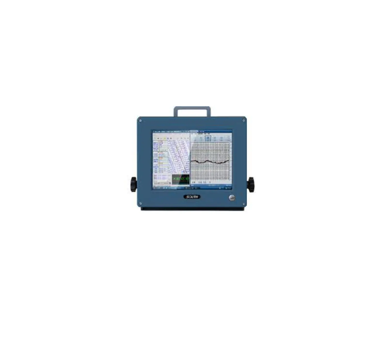
| Equipment under Test | : | Echo sounder |
| Model No. | : | SDE-230, SDE-230H, SDE-230+, SDE-230S, SDE- 230D, SDE-18, SDE-18+, SDE-18S, SDE-18D, SDE-19, SDE-19+, SDE-19S, SDE-19D, SDE-28, SDE-28+, SDE-28S, SDE-28D, SDE-28S+, SDE- 260, SDE-260+, SDE-260S, SDE-260D, SV20, SV30, SV40, SV50, SV60, SU12, SU17, SU20, SU30, SU36, SU40, SU50, SU60, SVP60 |
| Trade Mark | : | SOUTH, KOLIDA, SANDING, RUIDE, TIANYU |
| FCC ID | : | 2AJTU-SDE-230 |
| Manufacturer | : | South Surveying & Mapping Technology Co., Ltd. |
| Address | : | No.39, Sicheng Road, Tianhe District, Guangzhou |
Test Standard Used:
FCC Rules and Regulations Part 15 Subpart B
Test Procedure Used:
ANSI C63.4-2014, ANSI C63.4a-2017
We Declare:
The equipment described above is tested by Dongguan Dongdian Testing Service Co., Ltd. and in the configuration tested the equipment complied with the standards specified above. The test results are contained in this test report and Dongguan Dongdian Testing Service Co., Ltd. is assumed of full responsibility for the accuracy and completeness of these tests.
After test and evaluation, our opinion is that the equipment provided for test compliance with the requirement of the above FCC standard.
| Report No.: | DDT-R22060712-1E01 | ||
| Date of Receipt: | Jun. 08, 2022 | Date of Test: | Jun. 08, 2022 ~ Jul. 19, 2022 |
Prepared By:

Note: This report applies to above tested sample only. This report shall not be reproduced in parts without written approval of Dongguan Dongdian Testing Service Co., Ltd.
Revision History
| Rev. | Revisions | Issue Date | Revised By |
| — | Initial issue | Jul. 20, 2022 |
General Test Information
Description of EUT
| EUT* Name | : | Echo sounder |
| Model Number | : | SDE-230, SDE-230H, SDE-230+, SDE-230S, SDE-230D, SDE- 18, SDE-18+, SDE-18S, SDE-18D, SDE-19, SDE-19+, SDE-19S, SDE-19D, SDE-28, SDE-28+, SDE-28S, SDE-28D, SDE-28S+, SDE-260, SDE-260+, SDE-260S, SDE-260D, SV20, SV30, SV40, SV50, SV60, SU12, SU17, SU20, SU30, SU36, SU40, SU50, SU60, SVP60 |
| Model difference | : | Only the appearance is different, no other difference. So, choose SDE-230 to test. |
| EUT function description | : | Please reference user manual of this device |
| Power Supply | : | DC 12V powered by external adapter |
| EUT Class | : | Class A |
| Maximum work frequency | : | > 108 MHz |
| Sample Type | : | Series production |
| Serial Number | : | S22060712-01 |
Accessories of EUT
| Accessories | Manufacturer | Model number | Description |
| AC ADAPTER | CHANNEL WELL TECHNOLOGY | KPL-060F-VI | INPUT: 100-240V ~ 50/60Hz 1.7A OUTPUT: +12V5.0A 60.0W |
Block diagram EUT configuration for test
For mode 1: Full system
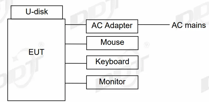
Test description: Use Brun In-Emerson software to run the EUT with a full system.
Decision of final test mode
| Conducted Emission | Mode 1 |
| Radiated emission | Mode 1 |
Deviations of test standard
No deviation.
Test environment conditions
During the measurement the environmental conditions were within the listed ranges:
| Temperature range: | 20-25 ℃ |
| Humidity range: | 40-75% |
| Pressure range: | 86-106kPa |
Note: The specific temperature and humidity information of each test item refers to the temperature and humidity record in the corresponding test data.
Test laboratory
Dongguan Dongdian Testing Service Co., Ltd.
Add.: No. 17, Zongbu Road 2, cLake Sci& Tech, Industry Park, Dongguan City,
Guangdong Province, China, 523808.
Tel.: +86-0769-38826678, http://www.dgddt.com, Email: [email protected].
CNAS Accreditation No. L6451; A2LA Accreditation Number: 3870.01
FCC Designation Number: CN1182, Test Firm Registration Number: 540522
Innovation, Science and Economic Development Canada Site Registration Number: 10288A
Conformity Assessment Body identifier: CN0048
VCCI facility registration number: C-20087, T-20088, R-20123, R-20155, G-20118
Measurement uncertainty
| Test Item | Uncertainty |
| Conducted disturbance at mains terminals | 1#: 3.72dB (9 kHz to 150 kHz), 3.34dB (150 kHz to 30 MHz) |
| 2#: 3.75dB (9 kHz to 150 kHz), 3.39dB (150 kHz to 30 MHz) | |
| 3#: 3.78dB (9 kHz to 150 kHz), 3.37dB (150 kHz to 30 MHz) | |
| Uncertainty for Antenna Power Conduction Measurement for Antenna port of Receivers | 1#: AAN with aLCL = 55 … 40 dBc: 3.64 dB AAN with aLCL = 65 … 50 dBc: 4.08 dB AAN with aLCL = 75 … 60 dBc: 4.56 dB |
| 2#: AAN with aLCL = 55 … 40 dBc: 3.82 dB AAN with aLCL = 65 … 50 dBc: 3.96 dB AAN with aLCL = 75 … 60 dBc: 4.12 dB | |
| Uncertainty for Radiation Emission test (30MHz-1GHz) | 1#: 4.94 dB (Antenna Polarize: V) 4.68 dB (Antenna Polarize: H) |
| 2#: 4.94 dB (Antenna Polarize: V) 4.68 dB (Antenna Polarize: H) | |
| 3#: 4.48 dB (Antenna Polarize: V) 4.64 dB (Antenna Polarize: H) | |
| 10m: 4.48 dB (Antenna Polarize: V) 4.64 dB (Antenna Polarize: H) | |
| Uncertainty for Radiation disturbance test (1GHz to 6GHz) | 1#: 4.10 dB (1-6 GHz) |
| 3#: 4.54 dB (1-6 GHz) | |
| Uncertainty for Radiation disturbance test (6GHz to 18GHz) | 1#: 4.40 dB (6-18 GHz) |
| 3#: 4.80 dB (6-18 GHz) | |
| Uncertainty for Radiation disturbance test (18GHz to 40GHz) | 1#: 4.58 dB (18-40 GHz) |
| 3#: 4.58 dB (18-40 GHz) | |
| Temperature | 0.4 ℃ |
| Humidity | 2% |
| Note: This uncertainty represents an expanded uncertainty expressed at approximately the 95% confidence level using a coverage factor of k=2. | |
Conducted Emission Test Report
Test equipment
| Equipment | Manufacturer | Model No. | Serial No. | Last Cal. | Cal. Interval |
| ☐ 1# Conducted emission | |||||
| Test Receiver | R&S | ESCI | 100551 | Sep. 02, 2021 | 1 Year |
| LISN 1 | R&S | ENV216 | 101109 | Sep. 07, 2021 | 1 Year |
| LISN 2 | R&S | ESH2-Z5 | 100309 | Sep. 07, 2021 | 1 Year |
| Pulse Limiter | R&S | ESH3-Z2 | 101242 | Sep. 02, 2021 | 1 Year |
| CE Cable 1 | HUBSER | N/A | W10.01 | Sep. 02, 2021 | 1 Year |
| Test software | Audix | E3 | V 6.11111b | N/A | N/A |
| ☒ 2# Conducted emission | |||||
| Test Receiver | R&S | ESCI | 101028 | Sep. 02, 2021 | 1 Year |
| LISN 1 | R&S | ENV216 | 101170 | Sep. 07, 2021 | 1 Year |
| LISN 2 | R&S | ENV216 | 101209 | Sep. 02, 2021 | 1 Year |
| Pulse Limiter | R&S | KH43101 | 4310118015 68-12# | May 17, 2022 | 1 Year |
| CE Cable 2 | HUBSER | RG214-5 | N/A | May 17, 2022 | 1 Year |
| Test software | Audix | E3 | V 6.11111b | N/A | N/A |
| ☐ 3# Conducted emission | |||||
| Test Receiver | R&S | ESCI | 101032 | Apr. 08, 2022 | 1 Year |
| LISN 1 | R&S | ENV216 | 101725 | Sep. 02, 2021 | 1 Year |
| LISN 2 | R&S | ENV216 | 101726 | Sep. 02, 2021 | 1 Year |
| LISN 3 | SCHWARZBECK | NSLK 8163 | 00017 | Sep. 02, 2021 | 1 Year |
| Pulse Limiter | SCHWARZBECK | VTSD 95 | 102766 | Sep. 02, 2021 | 1 Year |
| CE Cable 3 | HUBSER | Z806-NJ-NJ-2M | 21070280 | May. 19, 2021 | 1 Year |
| Test software | Audix | E3 | V 6.11111b | N/A | N/A |
| Notes. N/A means Not applicable. | |||||
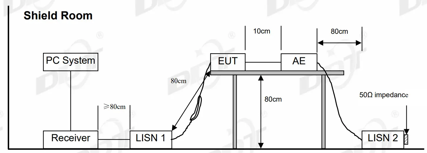
Block diagram of test setup
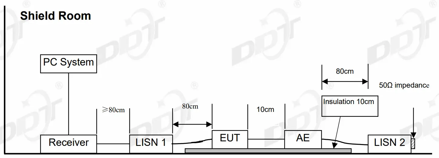
For table-top equipment
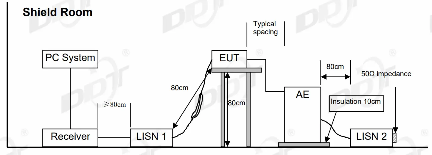
For floor standing equipment
For combinations equipment
Limits
Class A
Frequency | Quasi-Peak Level dB(mV) | Average Level dB(mV) | ||
150 kHz | ~ | 500 kHz | 79 | 66 |
| 500 kHz | ~ | 30 MHz | 73 | 60 |
Class B
Frequency | Quasi-Peak Level dB(mV) | Average Level dB(mV) |
150 kHz ~ 500 kHz | 66 ~ 56* | 56 ~ 46* |
500 kHz ~ 5 MHz | 56 | 46 |
| 5 MHz ~ 30 MHz | 60 | 50 |
- Notes: 1. * Decreasing linearly with logarithm of frequency.
- The lower limit shall apply at the transition frequencies.
Assistant equipment used for est
Assistant equipment | Manufacturer | Model number | Description | other |
| Mouse | N/A | N/A | N/A | N/A |
| Keyboard | N/A | N/A | N/A | N/A |
| U-disk | N/A | N/A | N/A | N/A |
| Monitor | N/A | N/A | N/A | N/A |
Test procedure
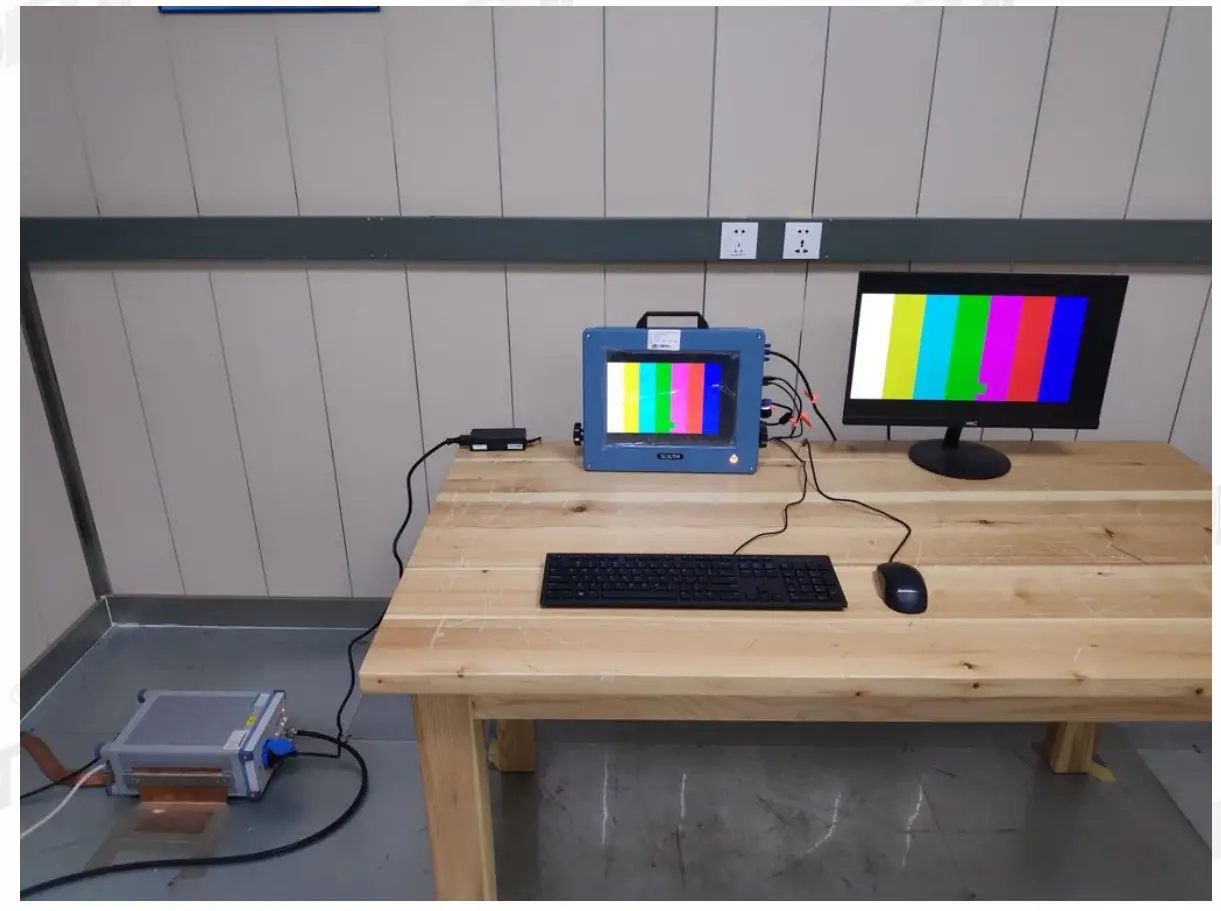
The EUT and Support equipment, if needed, were put placed on a non-metallic table, 0.8m (tabletop device)/0.1m (floor stand device) above the ground plane.
All I/O cables were positioned to simulate typical actual usage as per ANSI C63.4.
All support equipment power received from a second LISN.
Emissions were measured on each current carrying line of the EUT using an EMI Test Receiver connected to the LISN powering the EUT.
The Receiver scanned from 150 kHz to 30MHz for emissions in each of the test modes.
During the above scans, the emissions were maximized by cable manipulation.
The test mode(s) described in clause 2.3 were scanned during the preliminary test.
After the preliminary scan, we found the test mode producing the highest emission level.
The EUT configuration and worse cable configuration of the above highest emission levels were recorded for reference of the final test.
EUT and support equipment were set up on the test bench as per the configuration with highest emission level in the preliminary test.
A scan was taken on both power lines, Neutral and Line, recording at least the six highest emissions.
Emission frequency and amplitude were recorded into a computer in which correction factors werev used to calculate the emission level and compare reading to the applicable limit.
The test data of the worst-case condition(s) was recorded.
The bandwidth of test receiver is set at 9 kHz.
Test result
PASS. (See below detailed test result)
Note 1: All emissions not reported below are too low against the prescribed limits.
Note 2: “—–” means Peak detection; “—–” means Average detection.
TR-4-E-010 Conducted Emission Test Result
Test Site : DDT 5# Shield Room
Test Date : 2022-06-15
EUT : Echo sounder
Power Supply : AC 240V/50Hz
Condition : Temp:24.5°C,Humi:55.5%,Press:100.1kPa D:\2022 report data\Q22060712-1E\CE.EM6
Tested By : Sanqiang Pang
Model Number : SDE-230
Test Mode : Full system
LISN : 2021 2# ENV216/NEUTRAL
Memo
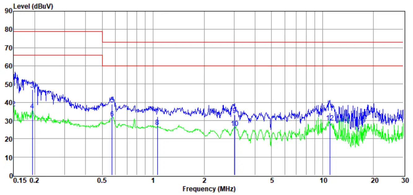
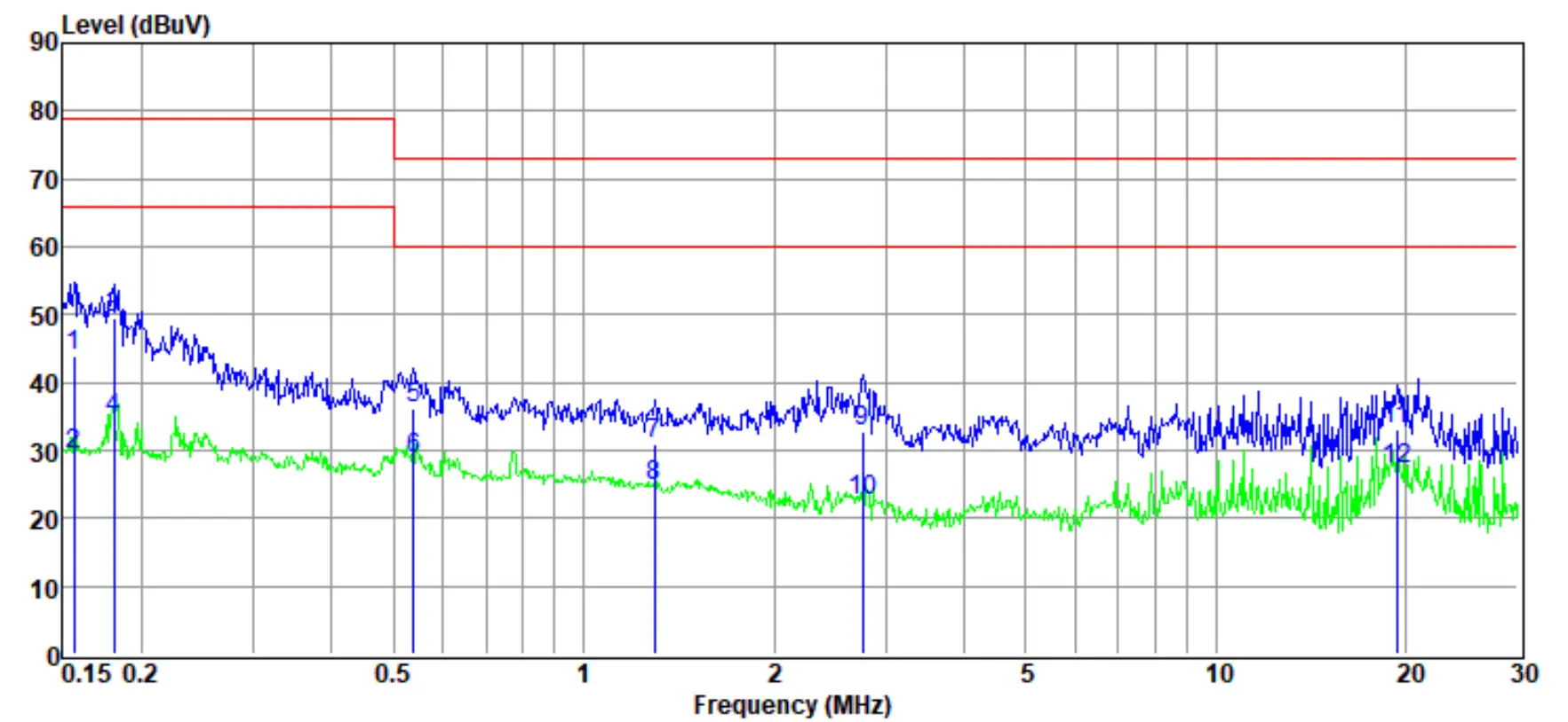
| Item (Mark) | Freq. (MHz) | Read Level (dBµV) | LISN Factor (dB) | Cable Loss (dB) | Pulse Limiter Factor (dB) | Result Level (dBµV) | Limit Line (dBµV) | Over Limit (dB) | Detector | Phase |
1 | 0.15 | 31.65 | 9.60 | 0.03 | 10.01 | 51.29 | 79.00 | -27.71 | QP | NEUTRAL |
| 2 | 0.15 | 17.12 | 9.60 | 0.03 | 10.01 | 36.76 | 66.00 | -29.24 | Average | NEUTRAL |
3 | 0.19 | 27.45 | 9.51 | 0.03 | 10.01 | 47.00 | 79.00 | -32.00 | QP | NEUTRAL |
| 4 | 0.19 | 16.02 | 9.51 | 0.03 | 10.01 | 35.57 | 66.00 | -30.43 | Average | NEUTRAL |
5 | 0.57 | 19.43 | 9.38 | 0.05 | 10.01 | 38.87 | 73.00 | -34.13 | QP | NEUTRAL |
| 6 | 0.57 | 11.93 | 9.38 | 0.05 | 10.01 | 31.37 | 60.00 | -28.63 | Average | NEUTRAL |
7 | 1.06 | 12.58 | 9.40 | 0.08 | 10.01 | 32.07 | 73.00 | -40.93 | QP | NEUTRAL |
| 8 | 1.06 | 6.97 | 9.40 | 0.08 | 10.01 | 26.46 | 60.00 | -33.54 | Average | NEUTRAL |
9 | 3.03 | 13.54 | 9.46 | 0.09 | 10.01 | 33.10 | 73.00 | -39.90 | QP | NEUTRAL |
| 10 | 3.03 | 6.39 | 9.46 | 0.09 | 10.01 | 25.95 | 60.00 | -34.05 | Average | NEUTRAL |
11 | 11.02 | 14.87 | 9.48 | 0.11 | 10.01 | 34.47 | 73.00 | -38.53 | QP | NEUTRAL |
| 12 | 11.02 | 9.40 | 9.48 | 0.11 | 10.01 | 29.00 | 60.00 | -31.00 | Average | NEUTRAL |
- Note: Result Level = Read Level +LISN Factor + Pulse Limiter Factor + Cable loss.
- If QP Result complies with AV limit, AV Result is deemed to comply with AV limit.
- Test setup: RBW: 200 Hz (9 kHz—150 kHz), 9 kHz (150 kHz—30 MHz).
- Step size: 80Hz (0.009MHz-0.15MHz), 4 kHz (0.15MHz-30MHz), Scan time: auto.
TR-4-E-010 Conducted Emission Test Result
| Test Site | : DDT 5# Shield Room | D:\2022 report data\Q22060712-1E\CE.EM6 |
| Test Date | : 2022-06-15 | Tested By: Sanqiang Pang |
| EUT | : Echo sounder | Model Number : SDE-230 |
| Power Supply | : AC 240V/50Hz | Test Mode: Full system |
| Condition | :Temp:24.5°C,Humi:55.5%,Press:100.1kPa | LISN: 2021 2# ENV216/LINE |
Memo :
Data: 4
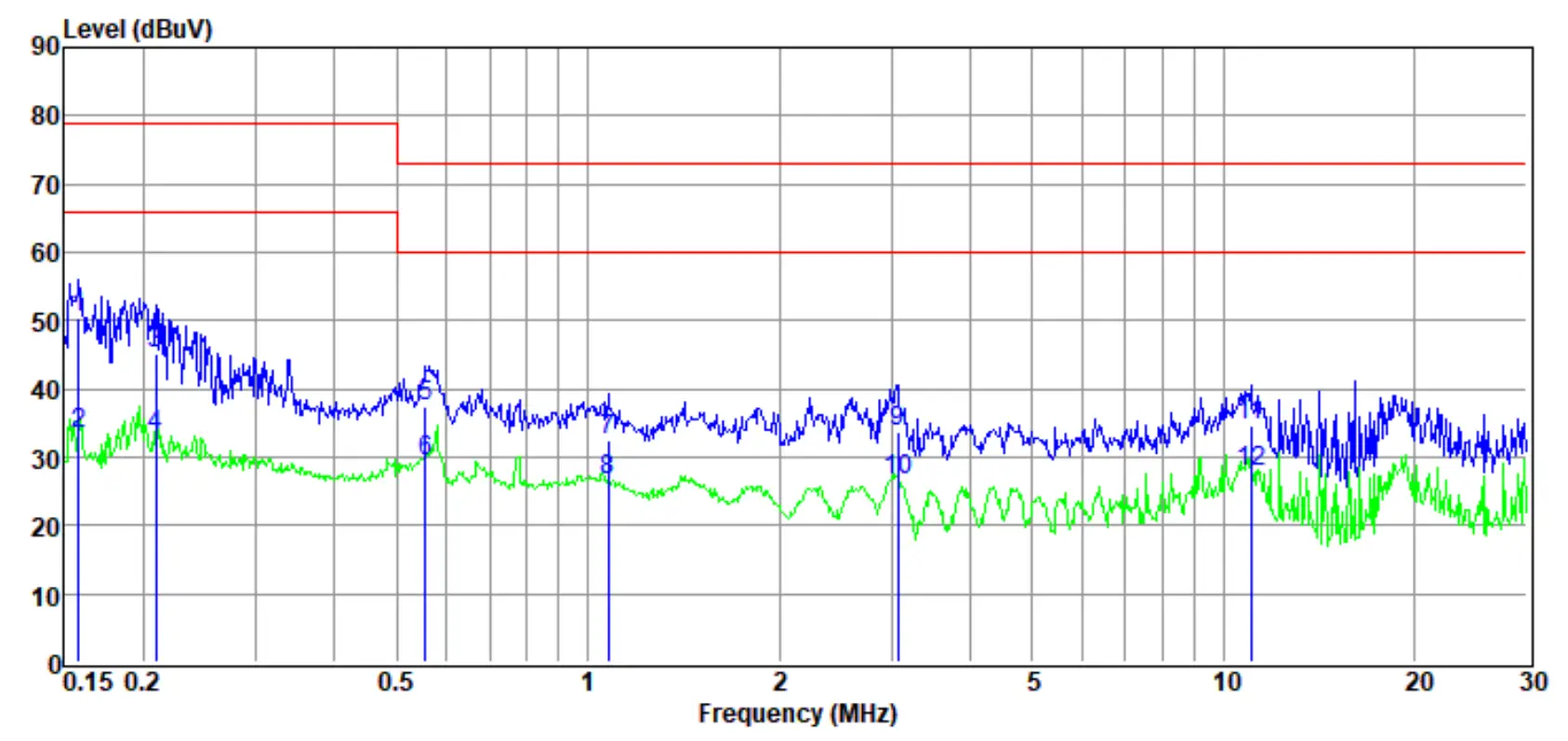
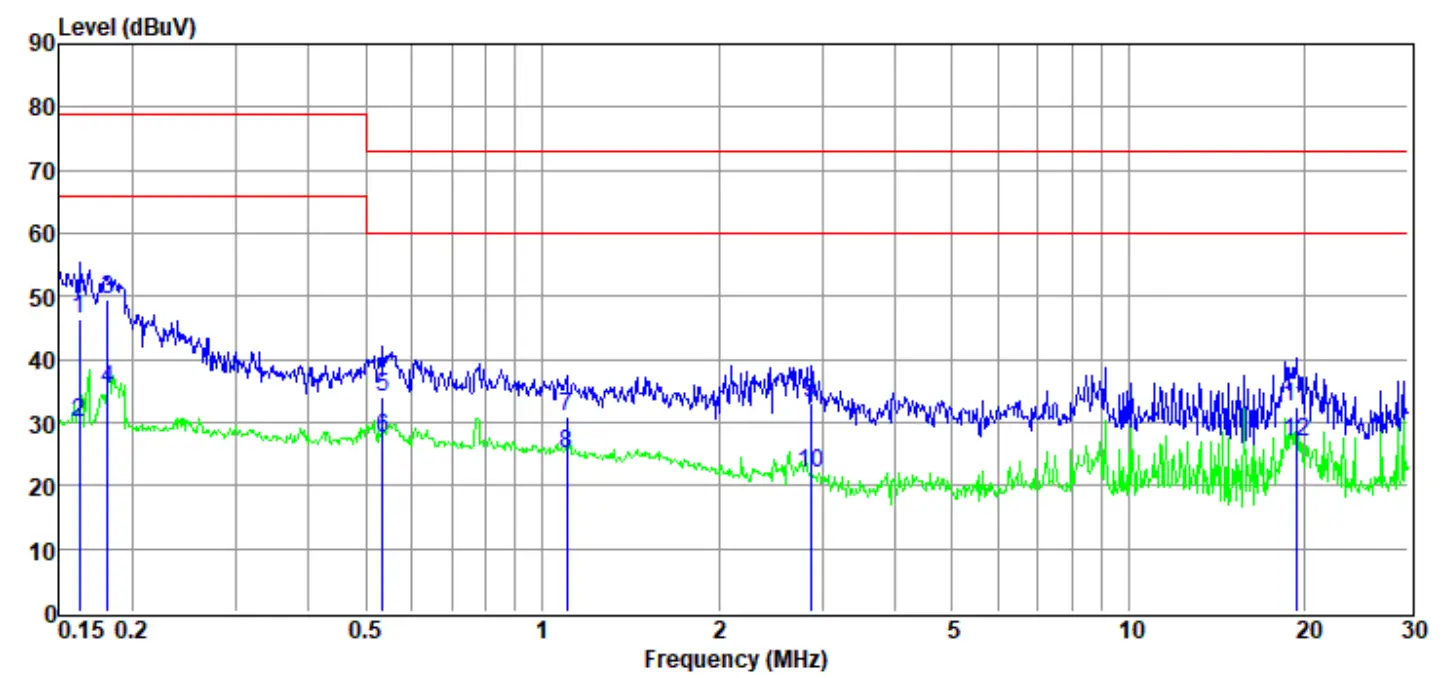
| Item (Mark) | Freq.(MHz) | Read Level (dBµV) | LISN Factor (dB) | Cable Loss (dB) | Pulse Limiter Facto (dB) | Result Level dBµV) | Limit Line (dBµV) | Over Limit (dB) | Detector | Phase |
1 | 0.16 | 30.90 | 9.44 | 0.03 | 10.01 | 50.38 | 79.00 | -28.62 | QP | LINE |
2 | 0.16 | 13.87 | 9.44 | 0.03 | 10.01 | 33.35 | 66.00 | -32.65 | Average | LINE |
| 3 | 0.21 | 25.65 | 9.58 | 0.04 | 10.01 | 45.28 | 79.00 | -33.72 | QP | LINE |
4 | 0.21 | 13.55 | 9.58 | 0.04 | 10.01 | 33.18 | 66.00 | -32.82 | Average | LINE |
| 5 | 0.56 | 18.00 | 9.27 | 0.05 | 10.01 | 37.33 | 73.00 | -35.67 | QP | LINE |
6 | 0.56 | 9.90 | 9.27 | 0.05 | 10.01 | 29.23 | 60.00 | -30.77 | Average | LINE |
| 7 | 1.08 | 13.10 | 9.30 | 0.08 | 10.01 | 32.49 | 73.00 | -40.51 | QP | LINE |
8 | 1.08 | 7.33 | 9.30 | 0.08 | 10.01 | 26.72 | 60.00 | -33.28 | Average | LINE |
| 9 | 3.07 | 14.22 | 9.36 | 0.09 | 10.01 | 33.68 | 73.00 | -39.32 | QP | LINE |
| 10 | 3.07 | 7.09 | 9.36 | 0.09 | 10.01 | 26.55 | 60.00 | -33.45 | Average | LINE |
11 | 11.02 | 15.18 | 9.27 | 0.11 | 10.01 | 34.57 | 73.00 | -38.43 | QP | LINE |
| 12 | 11.02 | 8.43 | 9.27 | 0.11 | 10.01 | 27.82 | 60.00 | -32.18 | Average | LINE |
- Note: Result Level = Read Level +LISN Factor + Pulse Limiter Factor + Cable loss.
- If QP Result complies with AV limit, AV Result is deemed to comply with AV limit.
- Test setup: RBW: 200 Hz (9 kHz—150 kHz), 9 kHz (150 kHz—30 MHz).
- Step size: 80Hz (0.009MHz-0.15MHz), 4 kHz (0.15MHz-30MHz), Scan time: auto.
TR-4-E-010 Conducted Emission Test Result
| Test Site | : DDT 5# Shield Room | D:\2022 report data\Q22060712-1E\CE.EM6 |
| Test Date | : 2022-06-15 | Tested By : Sanqiang Pang |
| EUT | : Echo sounder | Model Number : SDE-230 |
| Power Supply | : AC 120V/60Hz | Test Mode : Full system |
| Condition | : Temp:24.5°C,Humi:55.5%,Press:100.1kPa | LISN : 2021 2# ENV216/LINE |
Memo :
Data: 6
Item (Mark) | Freq. (MHz) | Read Level (dBµV) | LISN Factor (dB) | Cable Loss (dB) | Pulse Limiter Factor (dB) | Result Level (dBµV) | Limit Line (dBµV) | Over Limit (dB) | Detector | Phase |
1 | 0.16 | 24.37 | 9.43 | 0.03 | 10.01 | 43.84 | 79.00 | -35.16 | QP | LINE |
| 2 | 0.16 | 9.92 | 9.43 | 0.03 | 10.01 | 29.39 | 66.00 | -36.61 | Average | LINE |
3 | 0.18 | 30.05 | 9.53 | 0.03 | 10.01 | 49.62 | 79.00 | -29.38 | QP | LINE |
| 4 | 0.18 | 14.97 | 9.53 | 0.03 | 10.01 | 34.54 | 66.00 | -31.46 | Average | LINE |
| 5 | 0.54 | 16.85 | 9.28 | 0.05 | 10.01 | 36.19 | 73.00 | -36.81 | QP | LINE |
6 | 0.54 | 9.52 | 9.28 | 0.05 | 10.01 | 28.86 | 60.00 | -31.14 | Average | LINE |
| 7 | 1.30 | 11.42 | 9.30 | 0.08 | 10.01 | 30.81 | 73.00 | -42.19 | QP | LINE |
8 | 1.30 | 5.25 | 9.30 | 0.08 | 10.01 | 24.64 | 60.00 | -35.36 | Average | LINE |
| 9 | 2.77 | 13.25 | 9.35 | 0.08 | 10.01 | 32.69 | 73.00 | -40.31 | QP | LINE |
10 | 2.77 | 3.05 | 9.35 | 0.08 | 10.01 | 22.49 | 60.00 | -37.51 | Average | LINE |
| 11 | 19.33 | 13.55 | 9.41 | 0.12 | 10.02 | 33.10 | 73.00 | -39.90 | QP | LINE |
| 12 | 19.33 | 7.70 | 9.41 | 0.12 | 10.02 | 27.25 | 60.00 | -32.75 | Average | LINE |
- Note: Result Level = Read Level +LISN Factor + Pulse Limiter Factor + Cable loss.
- If QP Result complies with AV limit, AV Result is deemed to comply with AV limit.
- Test setup: RBW: 200 Hz (9 kHz—150 kHz), 9 kHz (150 kHz—30 MHz).
- Step size: 80Hz (0.009MHz-0.15MHz), 4 kHz (0.15MHz-30MHz), Scan time: auto.
TR-4-E-010 Conducted Emission Test Result
| Test Site | : DDT 5# Shield Room | D:\2022 report data\Q22060712-1E\CE.EM6 |
| Test Date | : 2022-06-15 | Tested By: Sanqiang Pang |
| EUT | : Echo sounder | Model Number : SDE-230 |
| Power Supply | : AC 120V/60Hz | Test Mode : Full system |
| Condition | : Temp:24.5°C,Humi:55.5%,Press:100.1kPa | LISN : 2021 2# ENV216/NEUTRAL |
Memo
Data: 8
Item (Mark) | Freq. (MHz) | Read Level (dBµV) | LISN Factor (dB) | Cable Loss (dB) | Pulse Limiter Factor (dB) | Result Level (dBµV) | Limit Line (dBµV) | Over Limit (dB) | Detector | Phase |
| 1 | 0.16 | 26.70 | 9.57 | 0.03 | 10.01 | 46.31 | 79.00 | -32.69 | QP | NEUTRAL |
| 2 | 0.16 | 10.28 | 9.57 | 0.03 | 10.01 | 29.89 | 66.00 | -36.11 | Average | NEUTRAL |
3 | 0.18 | 29.85 | 9.53 | 0.03 | 10.01 | 49.42 | 79.00 | -29.58 | QP | NEUTRAL |
| 4 | 0.18 | 15.65 | 9.53 | 0.03 | 10.01 | 35.22 | 66.00 | -30.78 | Average | NEUTRAL |
5 | 0.53 | 14.73 | 9.34 | 0.05 | 10.01 | 34.13 | 73.00 | -38.87 | QP | NEUTRAL |
| 6 | 0.53 | 8.22 | 9.34 | 0.05 | 10.01 | 27.62 | 60.00 | -32.38 | Average | NEUTRAL |
7 | 1.10 | 11.50 | 9.40 | 0.08 | 10.01 | 30.99 | 73.00 | -42.01 | QP | NEUTRAL |
| 8 | 1.10 | 5.71 | 9.40 | 0.08 | 10.01 | 25.20 | 60.00 | -34.80 | Average | NEUTRAL |
9 | 2.87 | 13.51 | 9.45 | 0.08 | 10.01 | 33.05 | 73.00 | -39.95 | QP | NEUTRAL |
| 10 | 2.87 | 2.39 | 9.45 | 0.08 | 10.01 | 21.93 | 60.00 | -38.07 | Average | NEUTRAL |
11 | 19.33 | 12.68 | 9.58 | 0.12 | 10.02 | 32.40 | 73.00 | -40.60 | QP | NEUTRAL |
12 | 19.33 | 7.21 | 9.58 | 0.12 | 10.02 | 26.93 | 60.00 | -33.07 | Average | NEUTRAL |
- Note: Result Level = Read Level +LISN Factor + Pulse Limiter Factor + Cable loss.
- If QP Result complies with AV limit, AV Result is deemed to comply with AV limit.
- Test setup: RBW: 200 Hz (9 kHz—150 kHz), 9 kHz (150 kHz—30 MHz).
- Step size: 80Hz (0.009MHz-0.15MHz), 4 kHz (0.15MHz-30MHz), Scan time: auto.
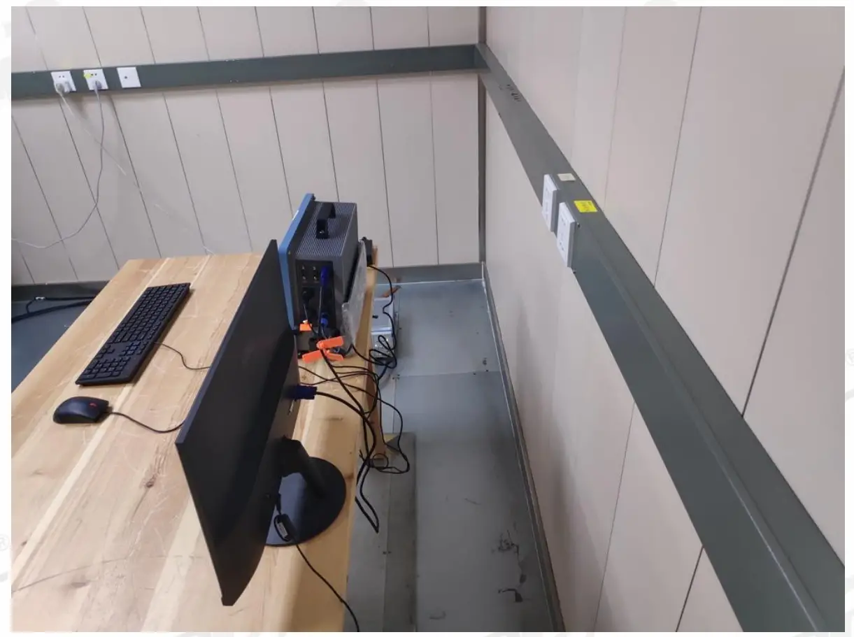
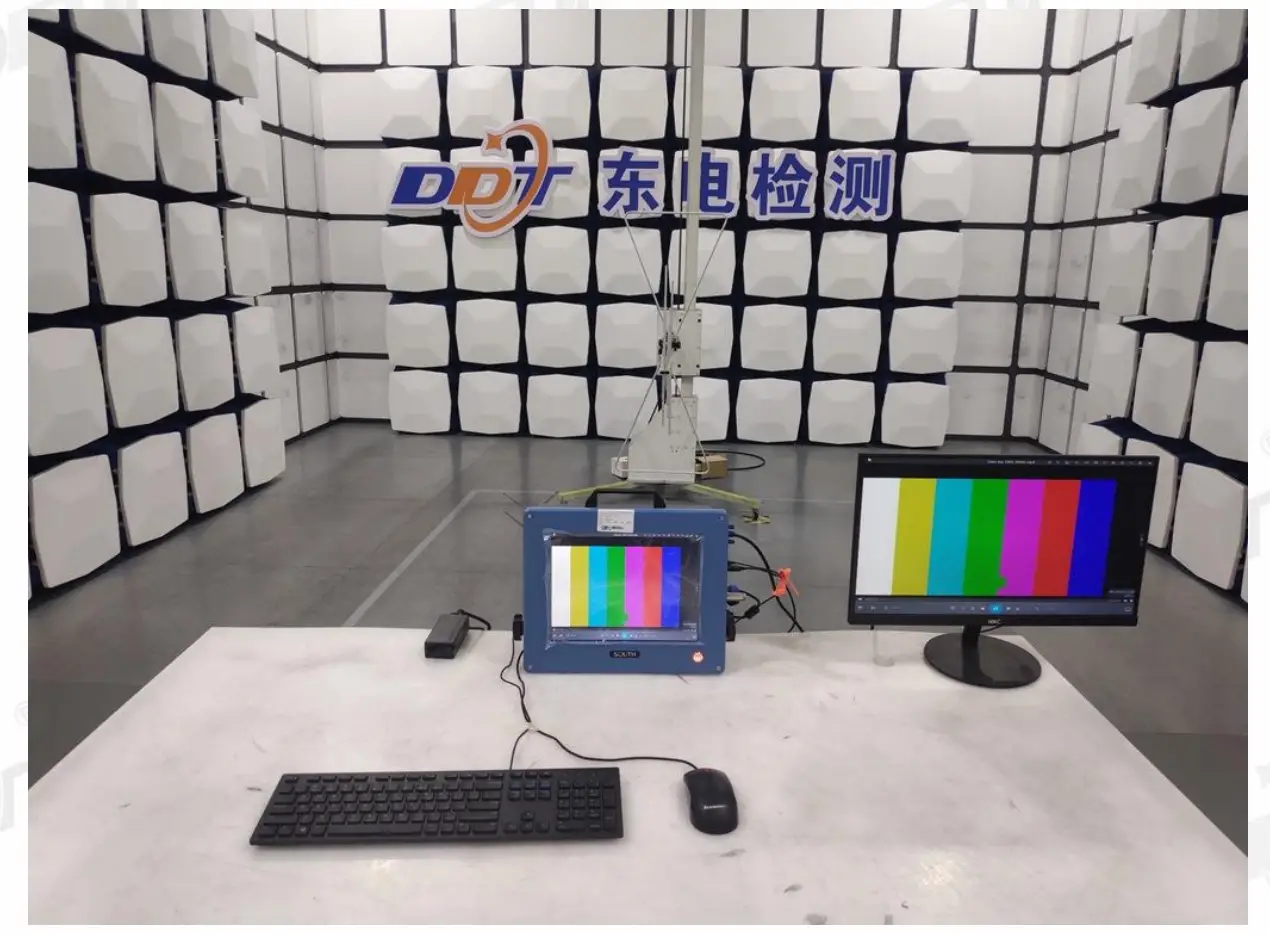
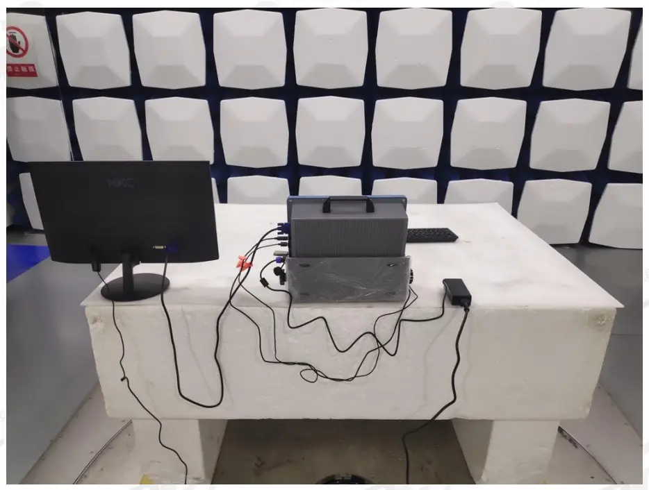
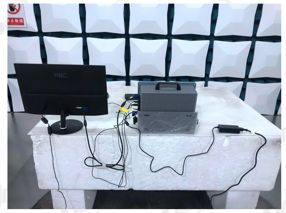
Test photo
Radiated Emissions Test
Test equipment
| Equipment | Manufacturer | Model No. | Serial No. | Last Cal. | Cal. Interval |
| ☒ 1# Radiation chamber | |||||
| EMI Test Receiver | R&S | ESU8 | 100316 | Sep. 02, 2021 | 1 Year |
| Spectrum analyzer | Agilent | E4447A | MY50180031 | May 18, 2022 | 1 Year |
| Trilog Broadband Antenna | Schwarz beck | VULB9163 | 9163-462 | Nov. 29, 2021 | 1 Year |
| Active Loop antenna | Schwarz beck | FMZB-1519 | 1519-038 | Sep. 19, 2021 | 1 Year |
| Double Ridged Horn Antenna | R&S | HF907 | 100276 | Sep. 19, 2021 | 1 Year |
| Broad Band Horn Antenna | Schwarz beck | BBHA 9170 | 790 | May 06, 2022 | 1 Year |
| Pre-amplifier | COM-POWER | PAM-118A | 18040119 | Sep. 09, 2021 | 1 Year |
| RF Cable | HUBSER | CP-X2+ CP-X1 | W11.03+ W12.02 | Sep. 02, 2021 | 1 Year |
| RF Cable | N/A | 5m+6m+1m | 06270619 | Sep. 02, 2021 | 1 Year |
| MI Cable | HUBSER | C10-01-01-1M | 1091629 | Sep. 02, 2021 | 1 Year |
| Test software | Audix | E3 | V 6.11111b | N/A | N/A |
| ☒ 2# Radiation chamber | |||||
| EMI Test Receiver | R&S | ESCI | 101028 | Sep. 02, 2021 | 1 Year |
| Spectrum analyzer | Agilent | E4440A | MY46185770 | May 18, 2022 | 1 Year |
| Trilog Broadband Antenna | Schwarz beck | VULB 9163 | 9163-994 | Sep. 27, 2021 | 1 Year |
| Trilog Broadband Antenna | Schwarz beck | VULB 9161 | 9161-4034 | Sep. 19, 2021 | 1 Year |
| Active Loop antenna | Schwarz beck | FMZB-1519 | 1519-038 | Sep. 19, 2021 | 1 Year |
| Double Ridged Horn Antenna | Schwarz beck | BBHA9120D | 9120D-2108 | Jul. 17, 2021 | 1 Year |
| Pre-amplifier | A.H. | PAM-0118 | 18040084 | Sep. 02, 2021 | 1 Year |
| RF Cable | MI Cable | RG214-11 | DDT- ZC01497 | May 17, 2022 | 1 Year |
| Test software | Audix | E3 | V 6.11111b | N/A | N/A |
| ☐ 3# Radiation chamber | |||||
| EMI Test Receiver | R&S | ESU26 | 100472 | May 18, 2022 | 1 Year |
| Spectrum analyzer | Agilent | E4447A | MY50180031 | May 18, 2022 | 1 Year |
| Active Loop antenna | Schwarz beck | FMZB-1519 | 1519-038 | Sep. 19, 2021 | 1 Year |
| Trilog Broadband Antenna | Schwarz beck | VULB 9163 | 01429 | Aug. 07, 2021 | 1 Year |
| Double Ridged Horn Antenna | Schwarz beck | BBHA9120 | 02108 | Jul. 17, 2021 | 1 Year |
| Broad Band Horn Antenna | Schwarz beck | BBHA 9170 | 790 | May 06, 2022 | 1 Year |
| Pre-amplifier | COM-POWER | PAM-118A | 18040084 | Sep. 02, 2021 | 1 Year |
| Pre-amplifier | COM-POWER | PAM-840A | 461369 | Apr. 11, 2022 | 1 Year |
| RF Cable | N/A | 14m | 6270619 | Sep. 02,2021 | 1 Year |
| Test software | Audix | E3 | V 6.1.1.1 | N/A | N/A |
| Notes. N/A means Not applicable. | |||||
Block diagram of test setup
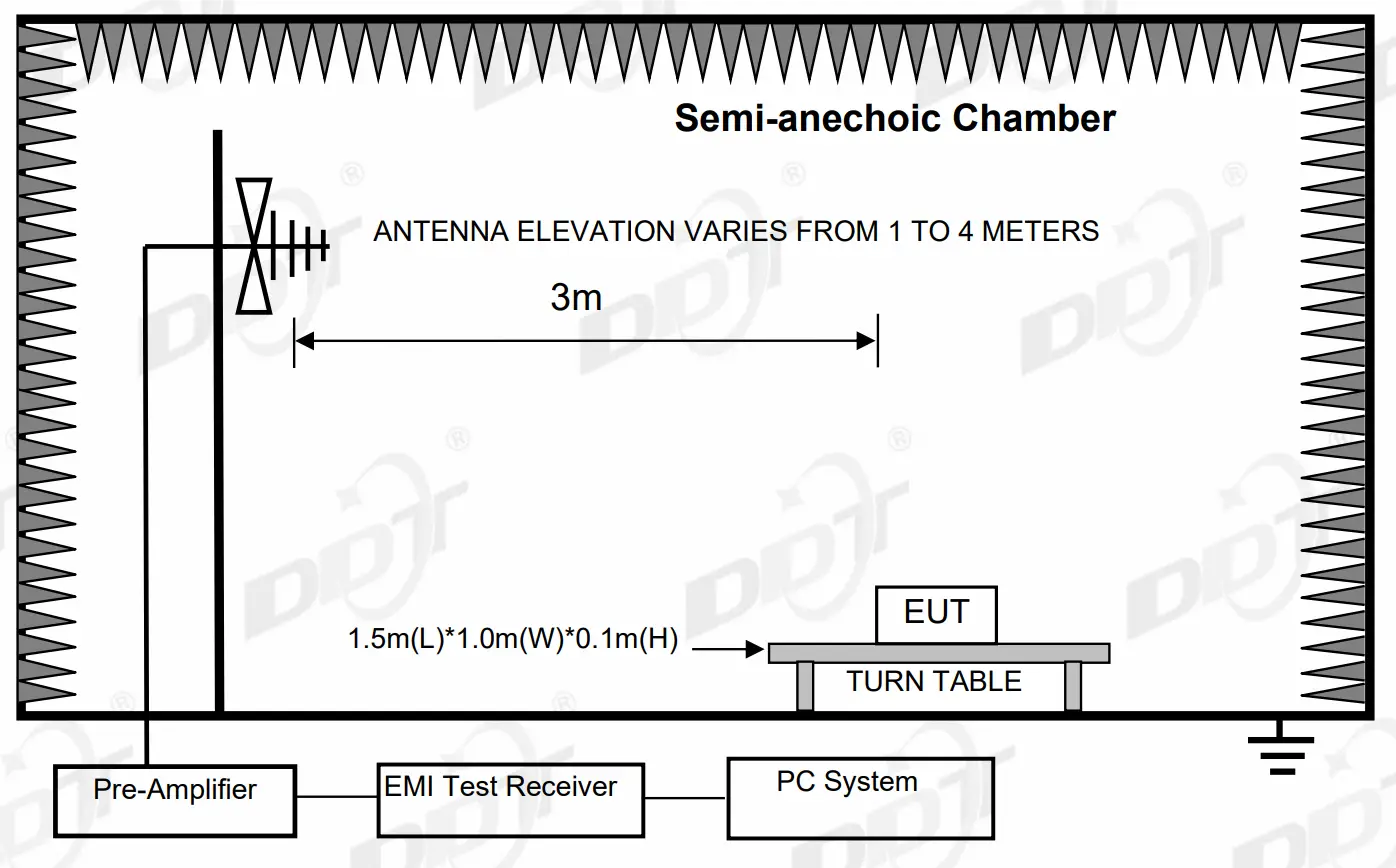
For floor standing equipment
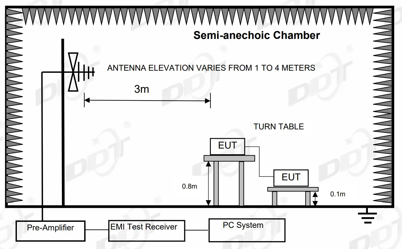
For combinations equipment
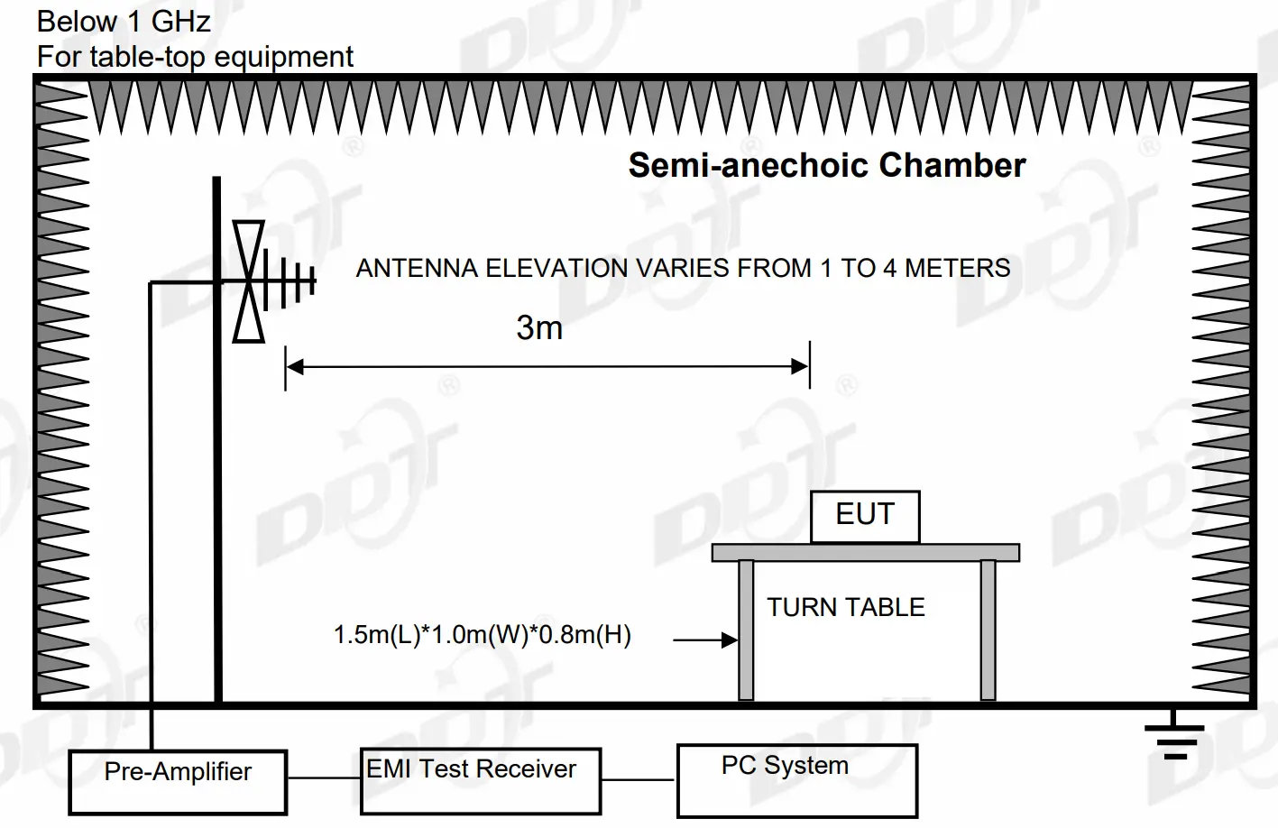
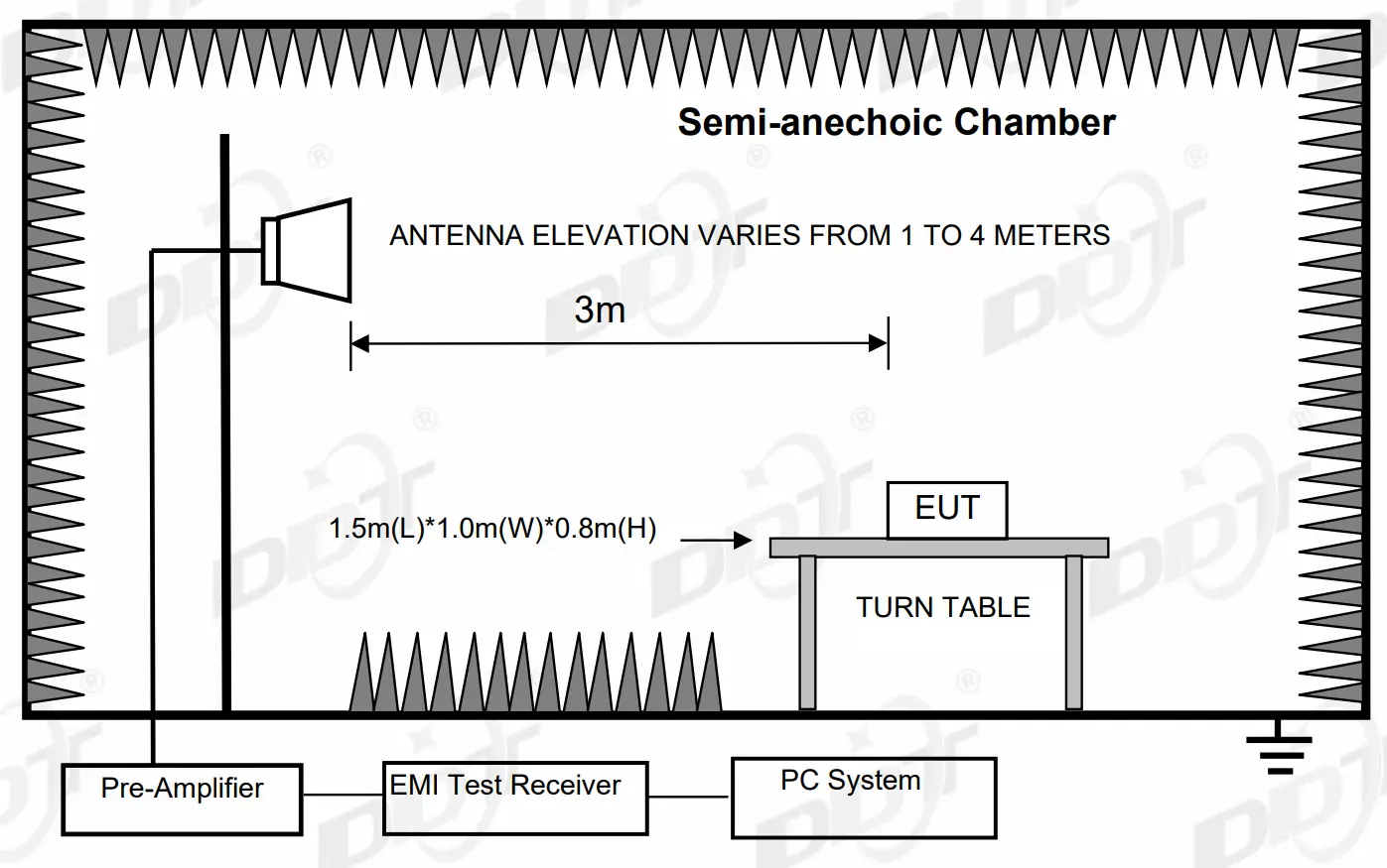
Above 1 GHz
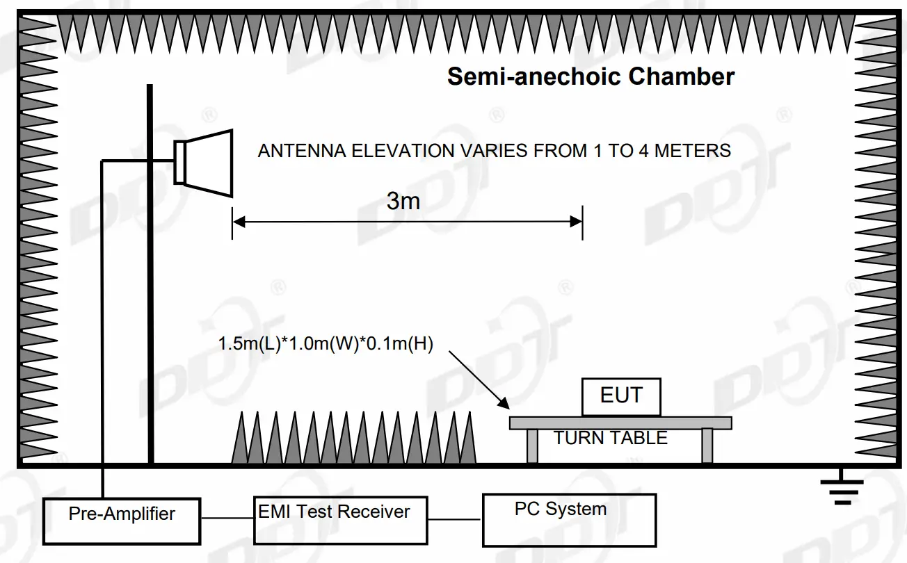
For table-top equipment
For floor standing equipment
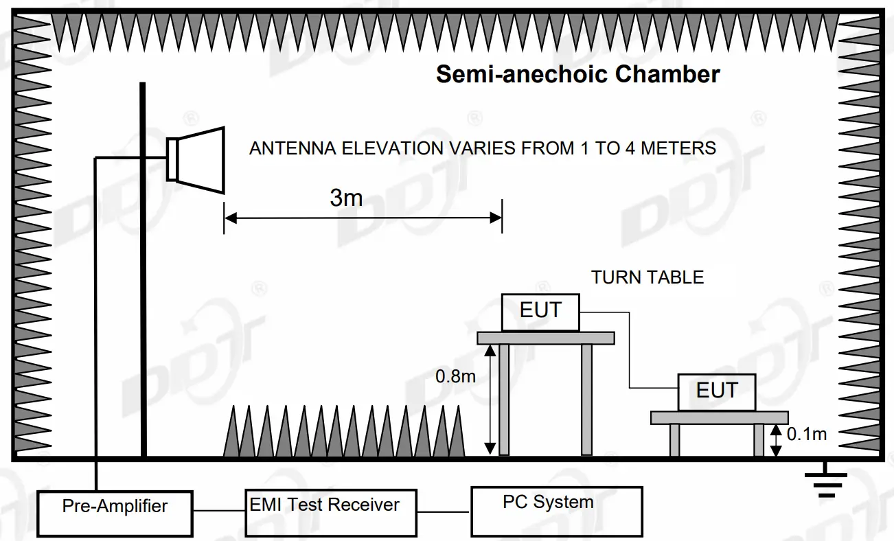
For combinations equipment
Limits
For FCC Rules and Regulations Part 15 Subpart B limits:
Frequency (MHz) | Class A Field Strengths Limits at 10m measuring distance dB(mV)/m | Class A Field Strengths Limits at 3m measuring distance dB(mV)/m | Class B Field Strengths Limits at 10m measuring distance dB(mV)/m | Class B Field Strengths Limits at 3m measuring distance dB(mV)/m |
30–88 | 39.0 | 49.5 | 29.5 | 40.0 |
| 88–216 | 43.5 | 54.0 | 33.0 | 43.5 |
| 216–960 | 46.4 | 57.0 | 35.5 | 46.0 |
960–1000 | 49.5 | 60.0 | 43.5 | 54.0 |
| Above 1000 | / | 80.0 Peak), 60.0 (Average) | / | 74.0 (Peak), 54.0 (Average) |
Note: (1) The smaller limit shall apply at the cross point between two frequency bands.
Note: (2) Test receiver use the Quasi-peak detector for testing in below 1GHz.
Assistant equipment used for test
| Assistant equipment | Manufacturer | Model number | Description | other |
Mouse | N/A | N/A | N/A | N/A |
| Keyboard | N/A | N/A | N/A | N/A |
U-disk | N/A | N/A | N/A | N/A |
| Monitor | N/A | N/A | N/A | N/A |
Test Procedure
Procedure of Preliminary Test
The EUT and Support equipment, if needed, were put placed on a non-metallic table, 0.8m (tabletop device)/0.1m (floor stand device) above the ground plane.
Configuration EUT to simulate typical usage as described in as shown above block diagram and equipment list of this report.
All I/O cables were positioned to simulate typical actual usage as per ANSI C63.4.
Mains cables, telephone lines or other connections to auxiliary equipment located outside the test are shall drape to the floor, be fitted with ferrite clamps or ferrite tubes placed on the floor at the point where the cable reaches the floor and then routed to the place where they leave the turntable. No extension cords shall be used to mains receptacle.
The antenna was placed at 3 meter away from the EUT as stated in ANSI C63.4. The antenna connected to the Spectrum Analyzer via a cable and at times a pre-amplifier would be used.
The Analyzer / Receiver quickly scanned from 30 MHz to ☐1 GHz / ☒18 GHz. The EUT test program was started. Emissions were scanned and measured rotating the EUT to 360 degrees and positioning the antenna 1 to 4 meters above the ground plane, in both the vertical and the horizontal polarization, to maximize the emission reading level.
The test mode(s) described in clause 2.3 were scanned during the preliminary test:
After the preliminary scan, we found the test mode producing the highest emission level. The EUT and cable configuration, antenna position, polarization and turntable position of the above highest emission level were recorded for the final test.
Procedure of Final Test
EUT and support equipment were set up on the turntable as per the configuration with highest emission level in the preliminary test. The Analyzer / Receiver scanned from 30 MHz to ☐1 GHz / ☒18 GHz. Emissions were scanned and measured rotating the EUT to 360 degrees, varying cable placement and positioning the antenna 1 to 4 meters above the ground plane, in both the vertical and the horizontal polarization, to maximize the emission reading level.
Recorded at least the six highest emissions. Emission frequency, amplitude, antenna position, polarization and turntable position were recorded into a computer in which correction factors were used to calculate the emission level and compare reading to the applicable limit and only Q.P. reading is presented.
For emissions from 30 MHz to 1 GHz, Quasi-Peak values were measured with EMI Receiver and the bandwidth of Receiver is 120 kHz.
For emissions above 1 GHz, both Peak and Average level were measured with Spectrum
Analyzer, and the RBW is set at 1 MHz VBW is set at 3 MHz.
The test data of the worst-case condition(s) was recorded.
Test result
PASS. (See below detailed test result)
Note 1: All emissions not reported below are too low against the prescribed limits.
Note 2: “—–” means Peak detection.
Note 3: According exploratory test, the emission levels are 20 dB below the limit detected from 9 kHz to 30 MHz and 18 GHz to 40 GHz, so the final test was performed with frequency range from 30 MHz to 18 GHz and recorded in below.
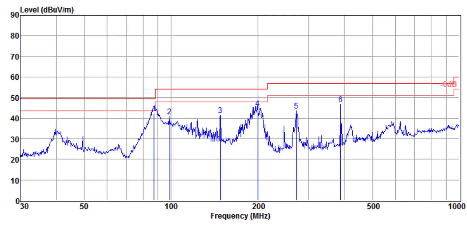
TR-4-E-009 Radiated Emission Test Result
| Test Site | : DDT 3m Chamber 2# | D:\2022 RE2# Report Data\Q22060712-1E\RE.EM6 |
| Test Date | : 2022-06-14 | Tested By : Sanqiang Pang |
| EUT | : Echo sounder | Model Number : SDE-230 |
| Power Supply | : AC 240V/50Hz | Test Mode : Full system |
| Condition | : Temp:24.5 °C,Humi:55%,Press:100.1kPa | Antenna/Distance : 2021 VULB 9163 #2/3m/VERTICAL |
Memo
Data: 21
| Item (Mark) | Freq. (MHz) | Read Level (dBµV) | Antenna Factor (dB/m) | Cable Loss dB | Result Level (dBµV/m) | Limit Line (dBµV/m) | Over Limit (dB) | Detector | Polarization |
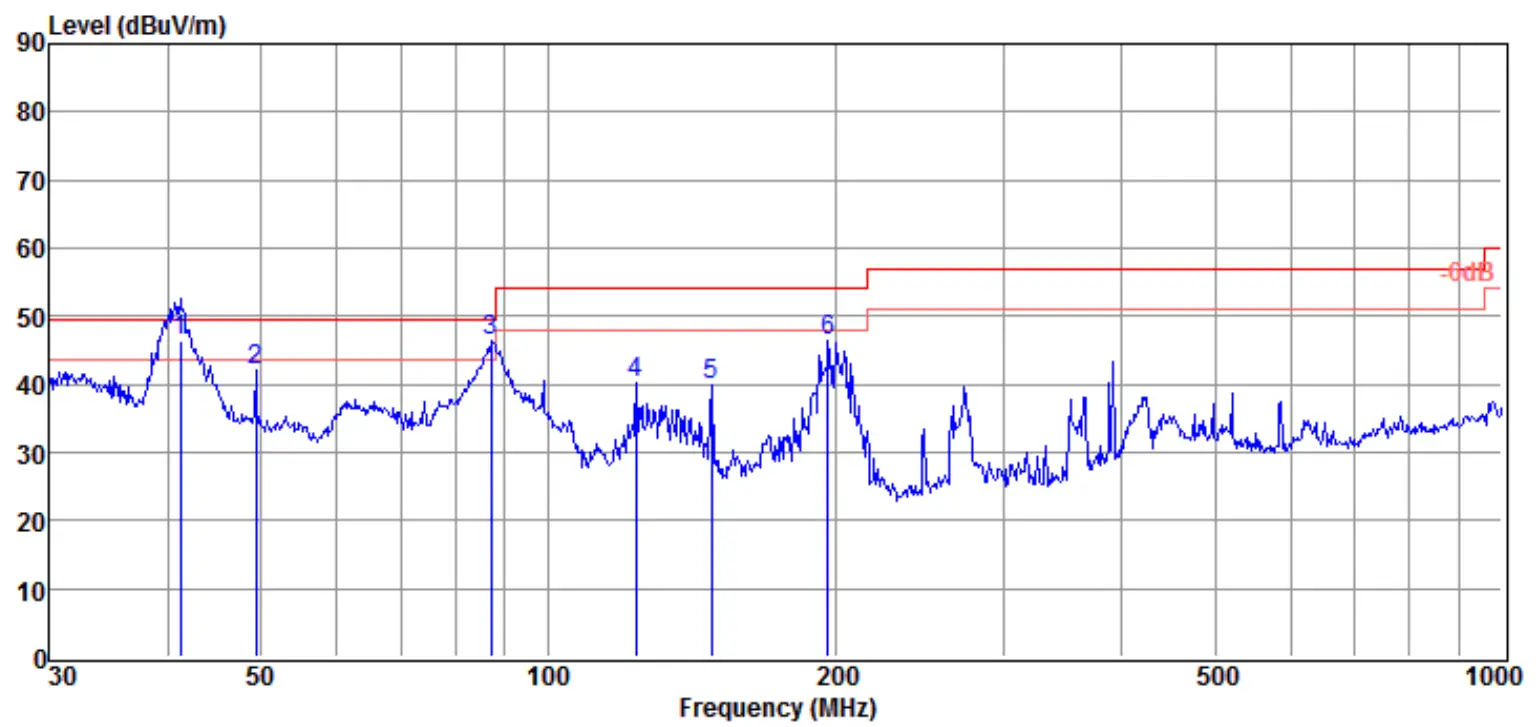
1 | 41.13 | 29.40 | 13.53 | 3.59 | 46.52 | 49.50 | -2.98 | QP | VERTICAL |
| 2 | 49.36 | 24.20 | 13.96 | 3.77 | 41.93 | 49.50 | -7.57 | QP | VERTICAL |
3 | 87.11 | 30.81 | 11.53 | 4.05 | 46.39 | 49.50 | -3.11 | QP | VERTICAL |
| 4 | 123.70 | 25.30 | 10.63 | 4.26 | 40.19 | 54.00 | -13.81 | QP | VERTICAL |
5 | 148.44 | 26.53 | 9.00 | 4.38 | 39.91 | 54.00 | -14.09 | QP | VERTICAL |
| 6 | 196.51 | 30.44 | 11.20 | 4.60 | 46.24 | 54.00 | -7.76 | QP | VERTICAL |
- Note: Result Level = Read Level + Antenna Factor + Cable loss.
- If Peak Result complies with QP limit, QP Result is deemed to comply with QP limit.
- Test setup: RBW: 120 kHz, VBW: 300 kHz, Sweep time: auto.
TR-4-E-009 Radiated Emission Test Result
| Test Site | : DDT 3m Chamber 2# | D:\2022 RE2# Report Data\Q22060712-1E\RE.EM6 |
| Test Date | : 2022-06-14 | Tested By : Sanqiang Pang |
| EUT | : Echo sounder | Model Number : SDE-230 |
| Power Supply | : AC 240V/50Hz | Test Mode : Full system |
| Condition | : Temp:24.5 °C,Humi:55%,Press:100.1kPa | Antenna/Distance : 2021 VULB 9163 #2/3m/HORIZONTAL |
Memo
Data: 22
| Item (Mark) | Freq. (MHz) | Read Level (dBµV) | Antenna Factor (dB/m) | Cable Loss dB | Result Level (dBµV/m) | Limit Line (dBµV/m) | Over Limit (dB) | Detector | Polarization |
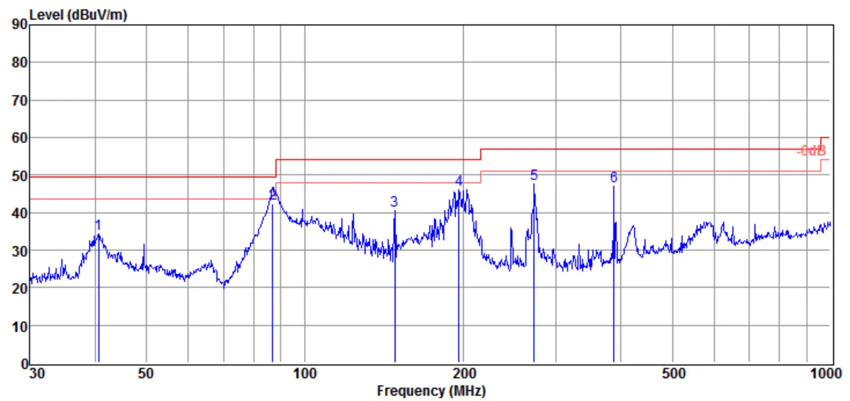
1 | 40.56 | 17.38 | 13.41 | 3.58 | 34.37 | 49.50 | -15.13 | QP | HORIZONTAL |
| 2 | 86.81 | 27.00 | 11.46 | 4.05 | 42.51 | 49.50 | -6.99 | QP | HORIZONTAL |
3 | 148.44 | 27.11 | 9.00 | 4.38 | 40.49 | 54.00 | -13.51 | QP | HORIZONTAL |
| 4 | 196.51 | 30.35 | 11.20 | 4.60 | 46.15 | 54.00 | -7.85 | QP | HORIZONTAL |
5 | 273.23 | 29.83 | 12.86 | 4.96 | 47.65 | 56.90 | -9.25 | QP | HORIZONTAL |
| 6 | 387.99 | 25.81 | 15.76 | 5.50 | 47.07 | 56.90 | -9.83 | QP | HORIZONTAL |
- Note: Result Level = Read Level + Antenna Factor + Cable loss.
- If Peak Result complies with QP limit, QP Result is deemed to comply with QP limit.
- Test setup: RBW: 120 kHz, VBW: 300 kHz, Sweep time: auto.
TR-4-E-009 Radiated Emission Test Result
| Test Site | : DDT 3m Chamber 2# | D:\2022 RE2# Report Data\Q22060712-1E\RE.EM6 |
| Test Date | : 2022-06-14 | Tested By : Sanqiang Pang |
| EUT | : Echo sounder | Model Number : SDE-230 |
| Power Supply | : AC 120V/60Hz | Test Mode : Full system |
| Condition | : Temp:24.5 °C,Humi:55%,Press:100.1kPa | Antenna/Distance : 2021 VULB 9163 #2/3m/HORIZONTAL |
Memo
Data: 23
Item (Mark) | Freq. (MHz) | Read Level (dBµV) | Antenna Factor (dB/m) | Cable Loss dB | Result Level (dBµV/m) | Limit Line (dBµV/m) | Over Limit (dB) | Detector | Polarization |
1 | 87.42 | 26.69 | 11.63 | 4.06 | 42.38 | 49.50 | -7.12 | QP | HORIZONTAL |
| 2 | 98.83 | 24.26 | 12.50 | 4.14 | 40.90 | 54.00 | -13.10 | QP | HORIZONTAL |
3 | 148.44 | 27.95 | 9.00 | 4.38 | 41.33 | 54.00 | -12.67 | QP | HORIZONTAL |
| 4 | 199.99 | 29.00 | 11.20 | 4.62 | 44.82 | 54.00 | -9.18 | QP | HORIZONTAL |
5 | 272.28 | 25.87 | 12.85 | 4.96 | 43.68 | 56.90 | -13.22 | QP | HORIZONTAL |
| 6 | 387.99 | 25.40 | 15.76 | 5.50 | 46.66 | 56.90 | -10.24 | QP | HORIZONTAL |
- Note: Result Level = Read Level + Antenna Factor + Cable loss.
- If Peak Result complies with QP limit, QP Result is deemed to comply with QP limit.
- Test setup: RBW: 120 kHz, VBW: 300 kHz, Sweep time: auto.
TR-4-E-009 Radiated Emission Test Result
| Test Site | : DDT 3m Chamber 2# | D:\2022 RE2# Report Data\Q22060712-1E\RE.EM6 |
| Test Date | : 2022-06-14 | Tested By : Sanqiang Pang |
| EUT | : Echo sounder | Model Number : SDE-230 |
| Power Supply | : AC 120V/60Hz | Test Mode : Full system |
| Condition | : Temp:24.5 °C,Humi:55%,Press:100.1kPa | Antenna/Distance : 2021 VULB 9163 #2/3m/VERTICAL |
Memo
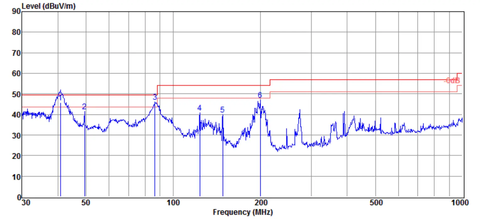
Data: 24
| Item (Mark) | Freq. (MHz) | Read Level (dBµV) | Antenna Factor (dB/m) | Cable Loss dB | Result Level (dBµV/m) | Limit Line (dBµV/m) | Over Limit (dB) | Detector | Polarization |
1 | 40.70 | 28.90 | 13.44 | 3.58 | 45.92 | 49.50 | -3.58 | QP | VERTICAL |
2 | 49.36 | 23.66 | 13.96 | 3.77 | 41.39 | 49.50 | -8.11 | QP | VERTICAL |
| 3 | 86.50 | 30.51 | 11.40 | 4.05 | 45.96 | 49.50 | -3.54 | QP | VERTICAL |
4 | 123.70 | 26.04 | 10.63 | 4.26 | 40.93 | 54.00 | -13.07 | QP | VERTICAL |
5 | 148.44 | 26.56 | 9.00 | 4.38 | 39.94 | 54.00 | -14.06 | QP | VERTICAL |
| 6 | 199.99 | 31.32 | 11.20 | 4.62 | 47.14 | 54.00 | -6.86 | QP | VERTICAL |
- Note: Result Level = Read Level + Antenna Factor + Cable loss.
- If Peak Result complies with QP limit, QP Result is deemed to comply with QP limit.
- Test setup: RBW: 120 kHz, VBW: 300 kHz, Sweep time: auto.
Radiated emission test (above 1GHz)
TR-4-E-009 Radiated Emission Test Result
Test Site : DDT 3m Chamber 1# D:\2022 RE 1# Report data\Q22060712-1E\RE-H.EM6
Test Date : 2022-06-17
EUT : Echo sounder
Power Supply : AC 120V/60Hz
Condition : TEMP:23.7°C, RH:56.3%, BP:101.4kPa
Tested By : Youbin He
Model Number : SDE-230
Test Mode : Full system
Antenna/Distance : 2021 HF907/3m/HORIZONTAL
Memo
Data: 5
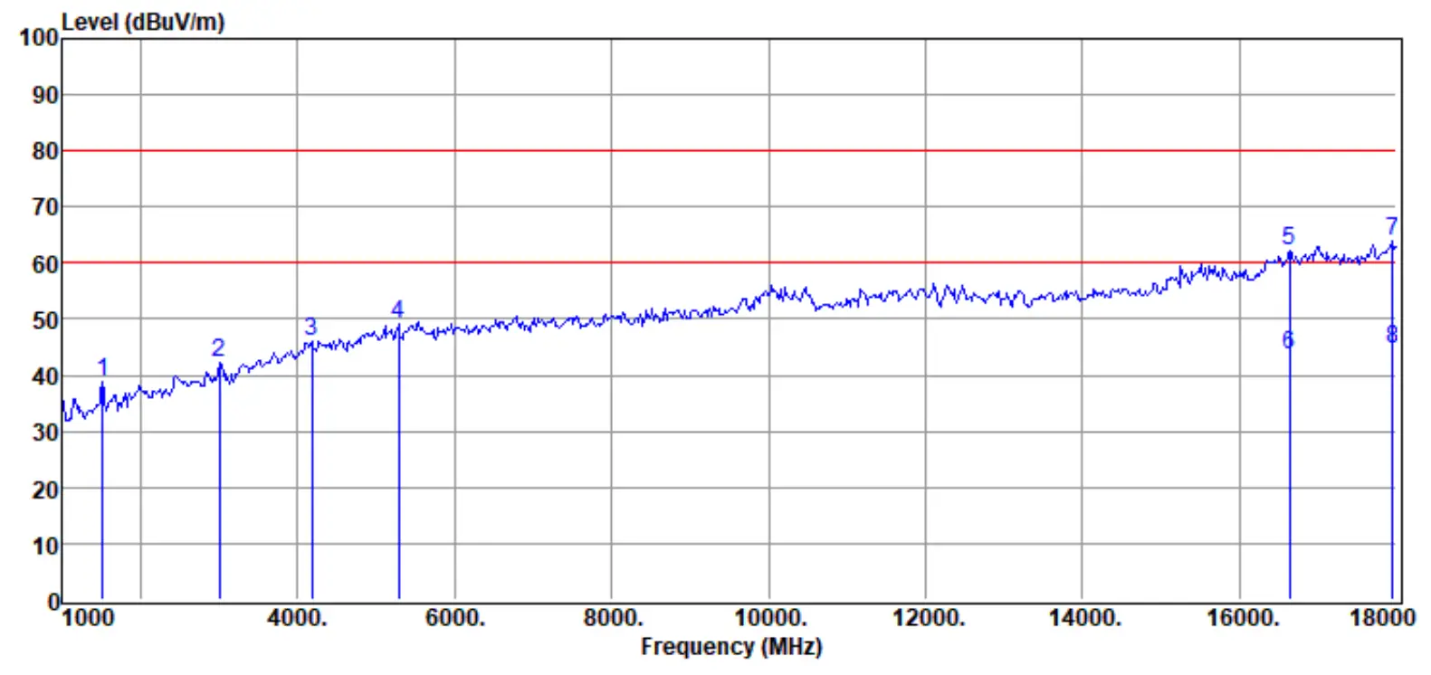
| Item (Mark) | Freq. (MHz) | Read Level (dBµV) | Antenna Factor (dB/m) | PRM Factor dB | Cable Loss dB | Result Level (dBµV/m) | Limit Line (dBµV/m) | Over Limit (dB) | Detector | Polarization |
1 | 1510.00 | 50.85 | 25.92 | 41.17 | 3.19 | 38.79 | 80.00 | -41.21 | Peak | HORIZONTAL |
| 2 | 3006.00 | 50.22 | 30.65 | 43.00 | 4.57 | 42.44 | 80.00 | -37.56 | Peak | HORIZONTAL |
3 | 4179.00 | 50.97 | 33.17 | 43.52 | 5.52 | 46.14 | 80.00 | -33.86 | Peak | HORIZONTAL |
| 4 | 5284.00 | 52.06 | 33.90 | 42.99 | 6.26 | 49.23 | 80.00 | -30.77 | Peak | HORIZONTAL |
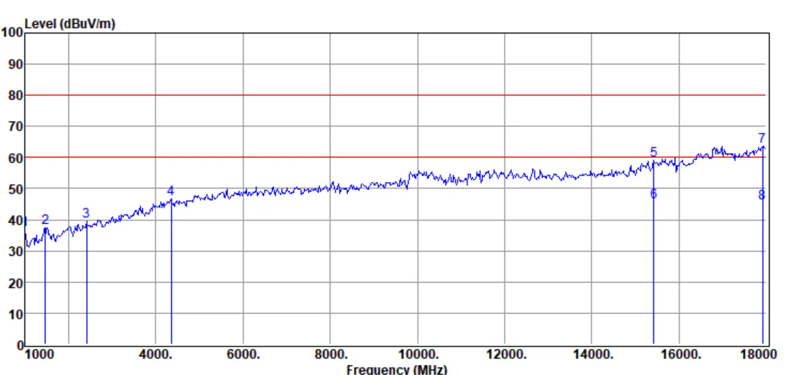
5 | 16640.00 | 47.05 | 43.28 | 40.38 | 12.17 | 62.12 | 80.00 | -17.88 | Peak | HORIZONTAL |
| 6 | 16640.00 | 28.64 | 43.28 | 40.38 | 12.17 | 43.71 | 60.00 | -16.29 | Average | HORIZONTAL |
7 | 17949.00 | 44.84 | 45.30 | 39.02 | 12.91 | 64.03 | 80.00 | -15.97 | Peak | HORIZONTAL |
| 8 | 17949.00 | 25.35 | 45.30 | 39.02 | 12.91 | 44.54 | 60.00 | -15.46 | Average | HORIZONTAL |
- Note: Result Level = Read Level + Antenna Factor + Cable loss – PRM Factor.
- If Peak Result complies with AV limit, AV Result is deemed to comply with AV limit.
- Test setup: RBW: 1 MHz, VBW: 3 MHz, Sweep time: auto.
TR-4-E-009 Radiated Emission Test Result
Test Site : DDT 3m Chamber 1# D:\2022 RE 1# Report data\Q22060712-1E\RE-H.EM6
Test Date : 2022-06-17
EUT : Echo sounder
Power Supply : AC 120V/60Hz
Condition : TEMP:23.7°C, RH:56.3%, BP:101.4kPa
Tested By : Youbin He
Model Number : SDE-230
Test Mode : Full system
Antenna/Distance : 2021 HF907/3m/VERTICAL
Memo
Data: 6
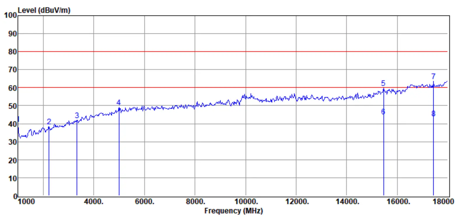
Item (Mark) | Freq. (MHz) | Read Level (dBµV) | Antenna Factor (dB/m) | PRM Factor dB | Cable Loss dB | Result Level (dBµV/m) | Limit Line (dBµV/m) | Over Limit (dB) | Detector | Polarization |
1 | 1000.00 | 51.94 | 25.40 | 40.40 | 2.85 | 39.79 | 80.00 | -40.21 | Peak | VERTICAL |
| 2 | 2224.00 | 48.41 | 28.26 | 42.04 | 3.75 | 38.38 | 80.00 | -41.62 | Peak | VERTICAL |
3 | 3329.00 | 48.69 | 31.57 | 43.22 | 4.84 | 41.88 | 80.00 | -38.12 | Peak | VERTICAL |
| 4 | 4995.00 | 52.07 | 34.19 | 43.20 | 6.05 | 49.11 | 80.00 | -30.89 | Peak | VERTICAL |
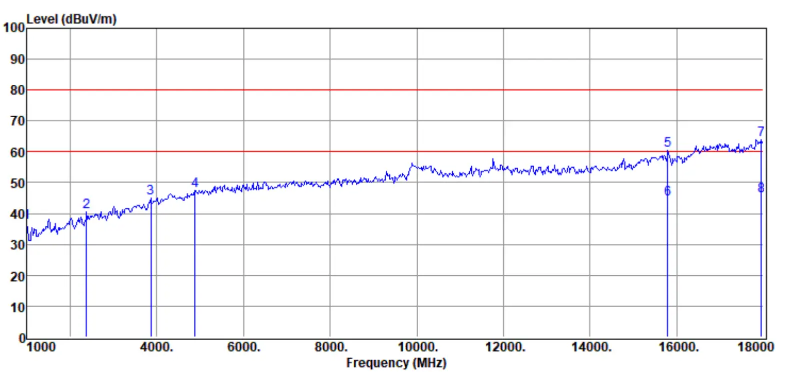
5 | 15450.00 | 49.17 | 41.40 | 42.00 | 11.22 | 59.79 | 80.00 | -20.21 | Peak | VERTICAL |
| 6 | 15450.00 | 33.34 | 41.40 | 42.00 | 11.22 | 43.96 | 60.00 | -16.04 | Average | VERTICAL |
7 | 17439.00 | 47.04 | 43.00 | 39.28 | 12.72 | 63.48 | 80.00 | -16.52 | Peak | VERTICAL |
| 8 | 17439.00 | 26.37 | 43.00 | 39.28 | 12.72 | 42.81 | 60.00 | -17.19 | Average | VERTICAL |
- Note: Result Level = Read Level + Antenna Factor + Cable loss – PRM Factor.
- If Peak Result complies with AV limit, AV Result is deemed to comply with AV limit.
- Test setup: RBW: 1 MHz, VBW: 3 MHz, Sweep time: auto.
TR-4-E-009 Radiated Emission Test Result
| Test Site | : DDT 3m Chamber 2# | D:\2022 RE2# Report Data\Q22060712-1E\RE.EM6 |
| Test Date | : 2022-06-14 | Tested By : Sanqiang Pang |
| EUT | : Echo sounder | Model Number : SDE-230 |
| Power Supply | : AC 120V/60Hz | Test Mode: Full system |
| Condition | : Temp:24.5 °C,Humi:55%,Press:100.1kPa | Antenna/Distance : 2021 VULB 9163 #2/3m/VERTICAL |
Memo
Data: 7
Item (Mark) | Freq (MHz) | Read Level (dBµV) | Antenna Factor (dB/m) | PRM Factor dB | Cable Loss dB | Result Level (dBµV/m) | Limit Line (dBµV/m) | Over Limit (dB) | Detector | Polarization |
1 | 1000.00 | 48.81 | 25.40 | 40.40 | 2.85 | 36.66 | 80.00 | -43.34 | Peak | VERTICAL |
| 2 | 1459.00 | 49.21 | 26.16 | 41.11 | 3.16 | 37.42 | 80.00 | -42.58 | Peak | VERTICAL |
3 | 2411.00 | 48.97 | 28.93 | 42.30 | 3.95 | 39.55 | 80.00 | -40.45 | Peak | VERTICAL |
| 4 | 4349.00 | 51.06 | 33.50 | 43.45 | 5.63 | 46.74 | 80.00 | -33.26 | Peak | VERTICAL |
5 | 15416.00 | 48.53 | 41.33 | 42.00 | 11.20 | 59.06 | 80.00 | -20.94 | Peak | VERTICAL |
| 6 | 15416.00 | 35.35 | 41.33 | 42.00 | 11.20 | 45.88 | 60.00 | -14.12 | Average | VERTICAL |
7 | 17915.00 | 44.61 | 45.23 | 39.04 | 12.90 | 63.70 | 80.00 | -16.30 | Peak | VERTICAL |
8 | 17915.00 | 26.23 | 45.23 | 39.04 | 12.90 | 45.32 | 60.00 | -14.68 | Average | VERTICAL |
- Note: Result Level = Read Level + Antenna Factor + Cable loss – PRM Factor.
- If Peak Result complies with AV limit, AV Result is deemed to comply with AV limit.
- Test setup: RBW: 1 MHz, VBW: 3 MHz, Sweep time: auto.
TR-4-E-009 Radiated Emission Test Result \
| Test Site | : DDT 3m Chamber 2# | D:\2022 RE2# Report Data\Q22060712-1E\RE.EM6 |
| Test Date | : 2022-06-14 | Tested By : Sanqiang Pang |
| EUT | : Echo sounder | Model Number : SDE-230 |
| Power Supply | : AC 120V/60Hz | Test Mode: Full system |
| Condition | : Temp:24.5 °C,Humi:55%,Press:100.1kPa | Antenna/Distance : 2021 HF907/3m/HORIZONTAL Memo |
Memo
Data: 8
Item (Mark) | Freq. (MHz) | Read Level (dBµV) | Antenna Factor (dB/m) | PRM Factor dB | Cable Los dB | Result Level (dBµV/m) | Limit Line (dBµV/m) | Over Limit (dB) | Detector | Polarization |
1 | 1000.00 | 49.39 | 25.40 | 40.40 | 2.85 | 37.24 | 80.00 | -42.76 | Peak | HORIZONTAL |
| 2 | 2377.00 | 50.44 | 28.48 | 42.25 | 3.91 | 40.58 | 80.00 | -39.42 | Peak | HORIZONTAL |
3 | 3856.00 | 50.64 | 32.61 | 43.52 | 5.28 | 45.01 | 80.00 | -34.99 | Peak | HORIZONTAL |
| 4 | 4876.00 | 50.95 | 33.90 | 43.25 | 5.97 | 47.57 | 80.00 | -32.43 | Peak | HORIZONTAL |
5 | 15790.00 | 49.15 | 41.87 | 42.00 | 11.39 | 60.41 | 80.00 | -19.59 | Peak | HORIZONTAL |
| 6 | 15790.00 | 33.35 | 41.87 | 42.00 | 11.39 | 44.61 | 60.00 | -15.39 | Average | HORIZONTAL |
7 | 17949.00 | 44.80 | 45.30 | 39.02 | 12.91 | 63.99 | 80.00 | -16.01 | Peak | HORIZONTAL |
| 8 | 17949.00 | 26.36 | 45.30 | 39.02 | 12.91 | 45.55 | 60.00 | -14.45 | Average | HORIZONTAL |
- Note: Result Level = Read Level + Antenna Factor + Cable loss – PRM Factor.
- If Peak Result complies with AV limit, AV Result is deemed to comply with AV limit.
- Test setup: RBW: 1 MHz, VBW: 3 MHz, Sweep time: auto.
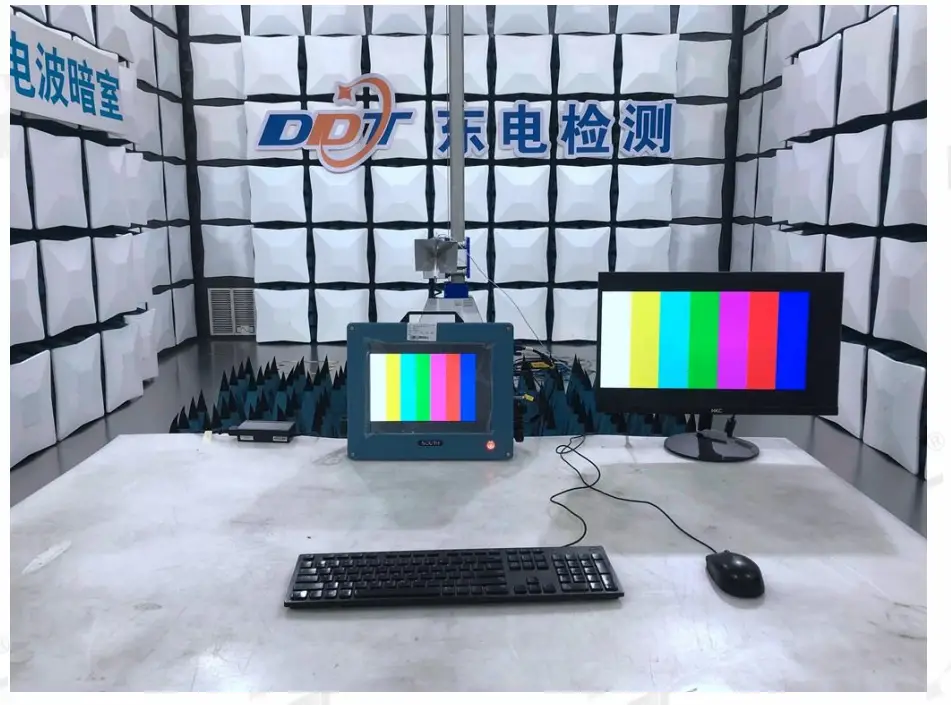
Test photo
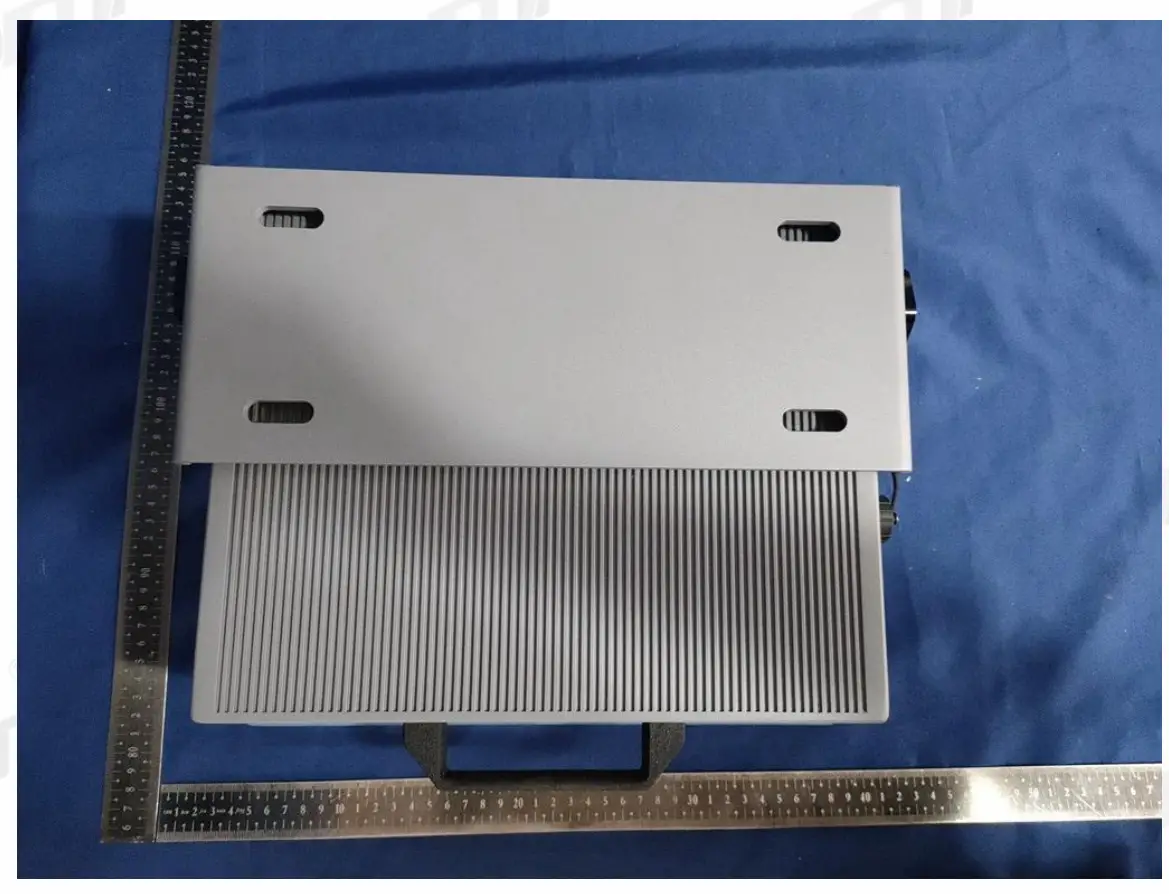
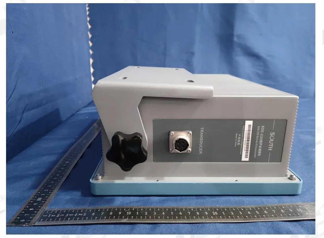
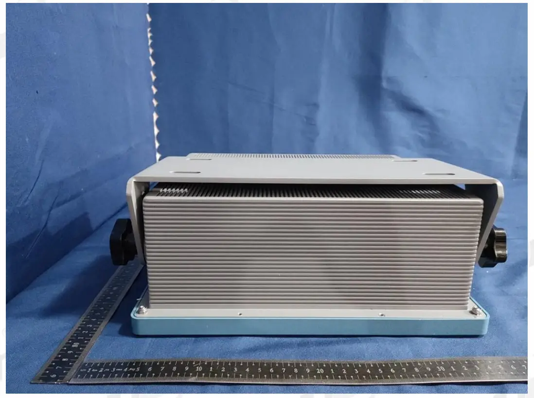
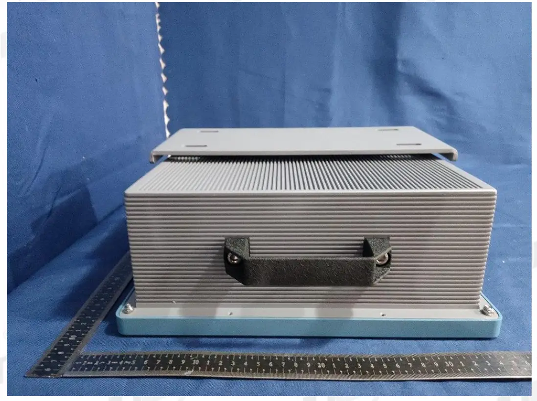
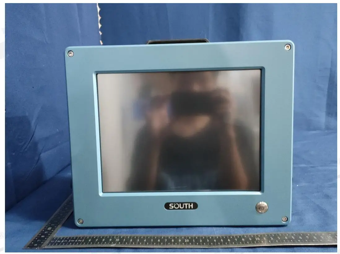
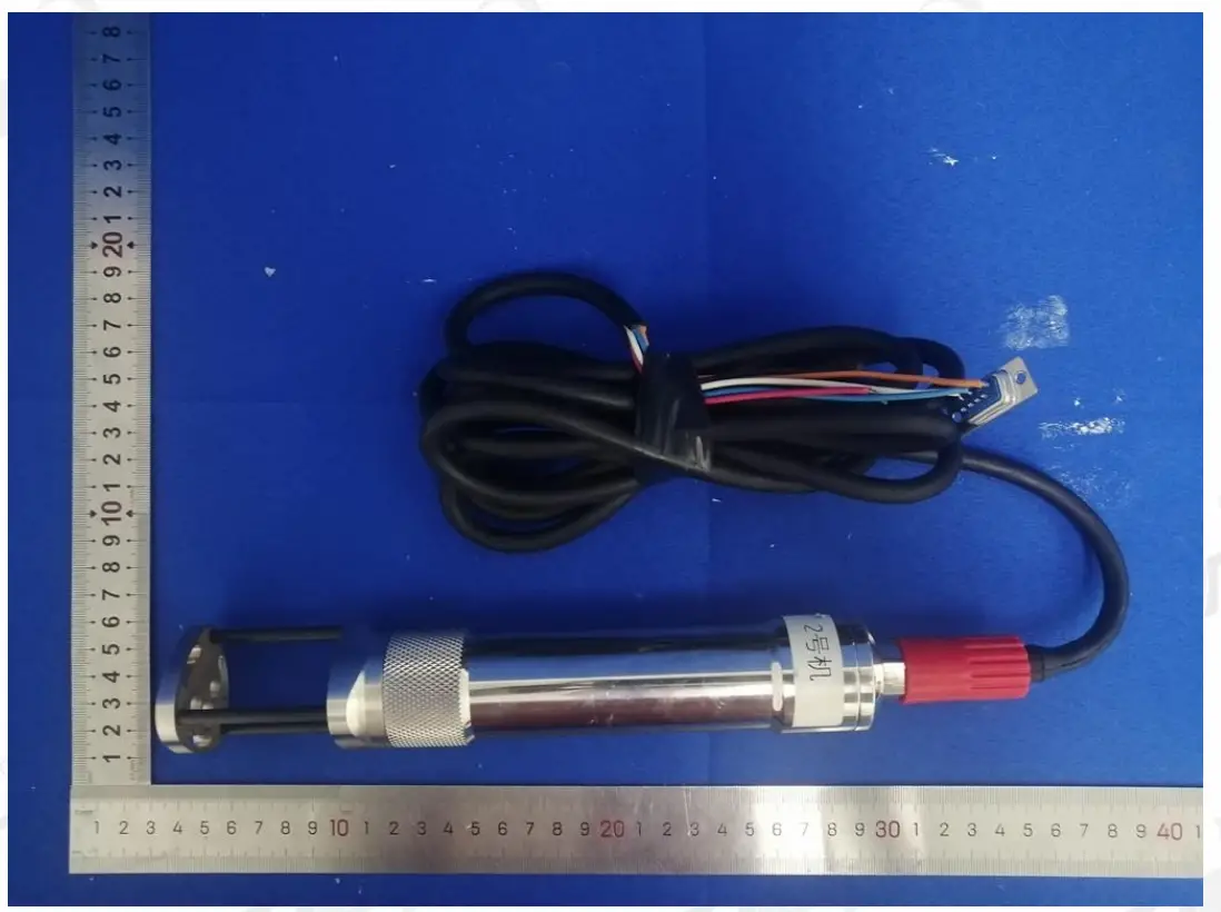
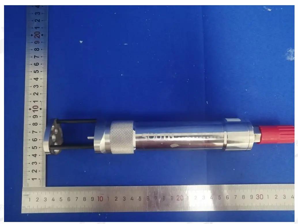
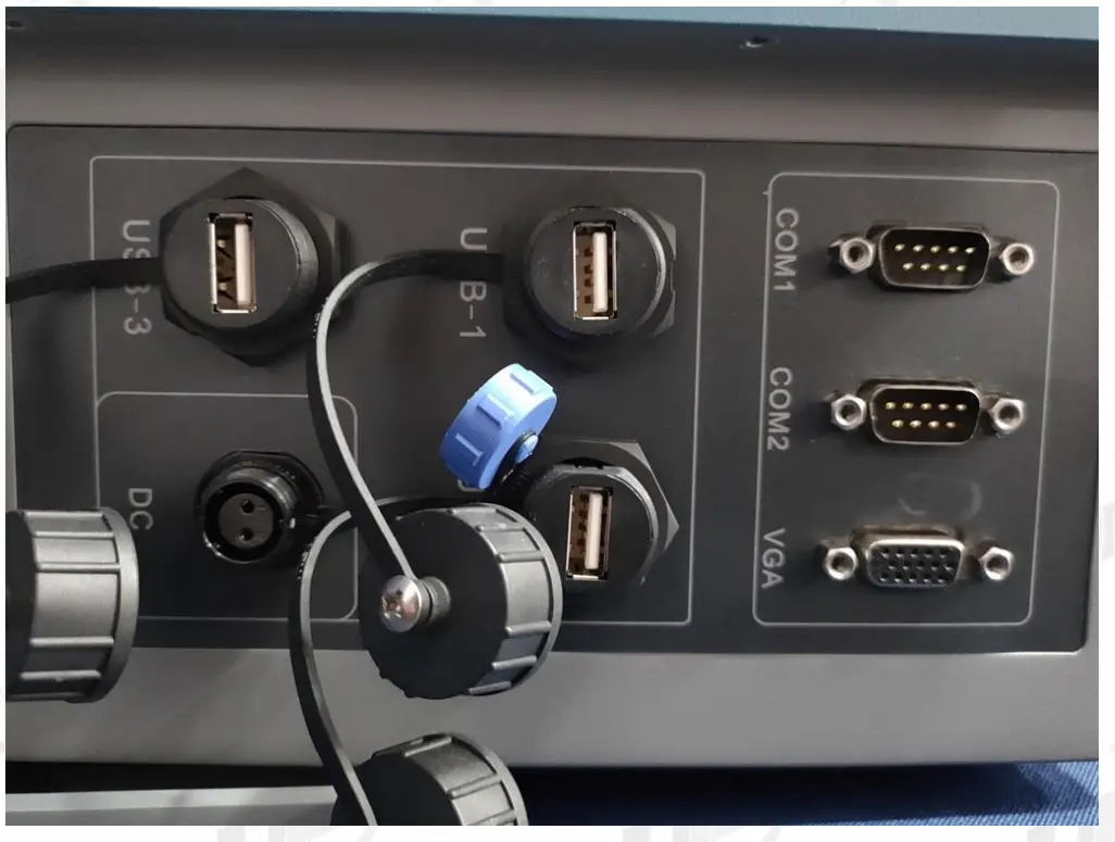
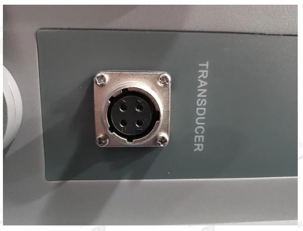
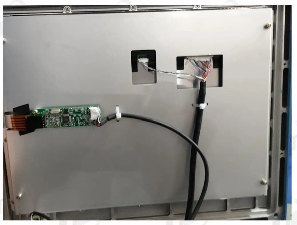
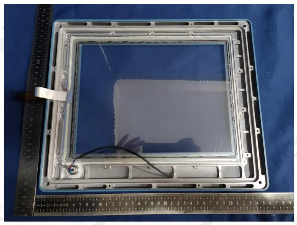
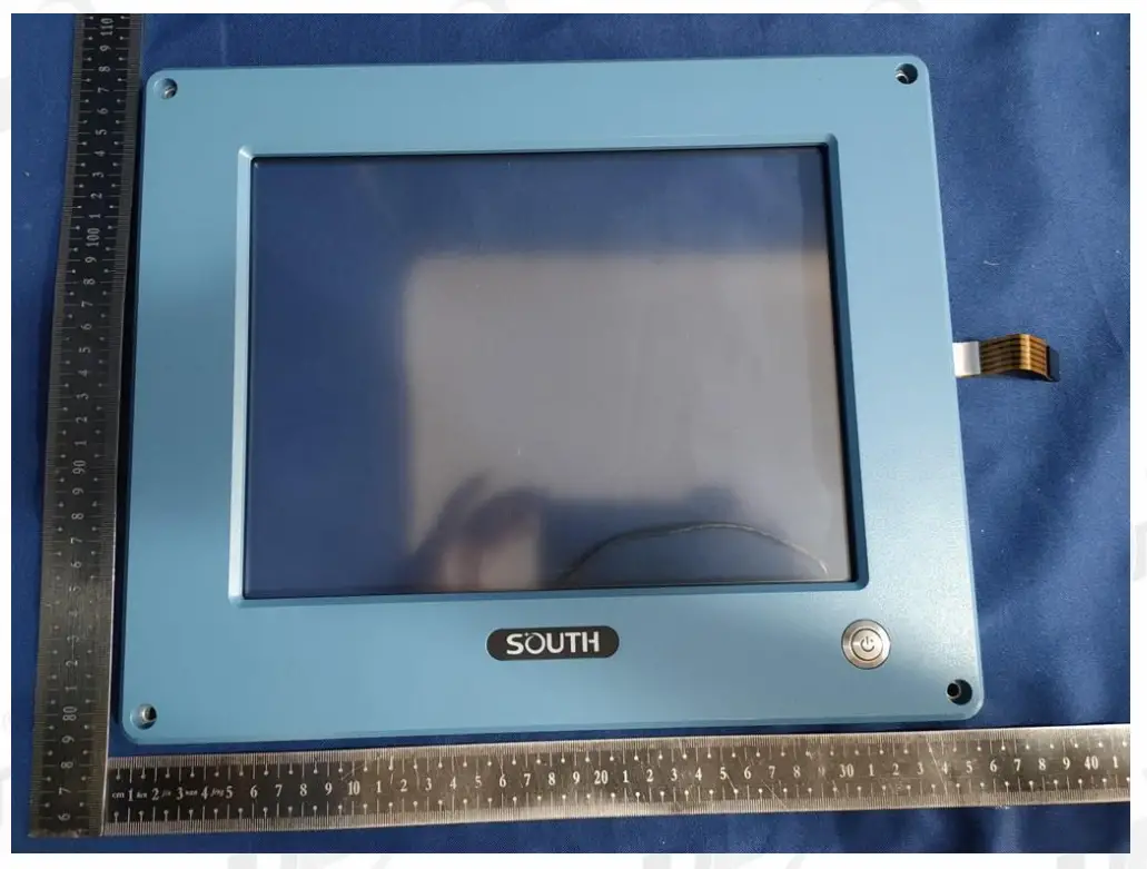
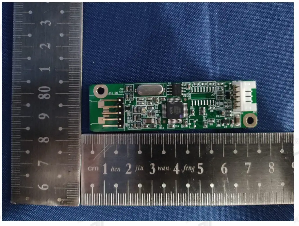
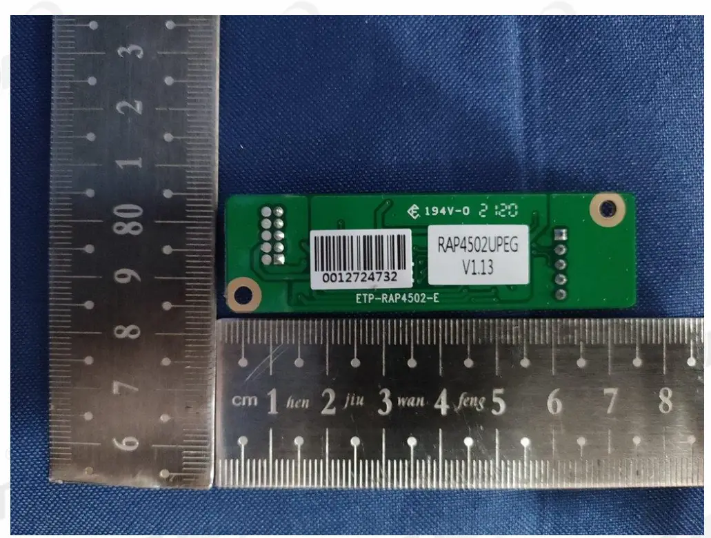
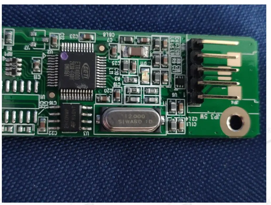
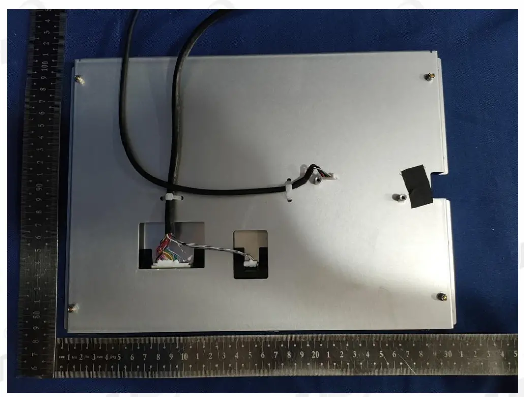
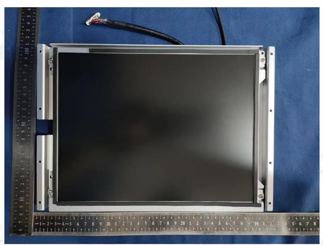
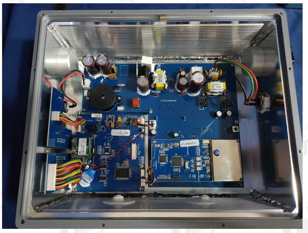
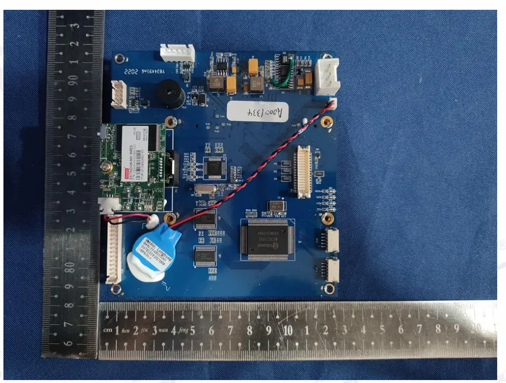
Photos of the EUT

CUSTOMER SUPPORT
Issued By: Dongguan Dongdian Testing Service Co., Ltd.
Add.: No. 17, Zongbu Road 2, Songshan Lake Sci&Tech, Industry Park,
Dongguan City, Guangdong Province, China, 523808
Tel.: +86-0769-38826678, E-mail: [email protected], http://www.dgddt.com