![]() CRANE SCALE TCB SERIES
CRANE SCALE TCB SERIES
TCB SERIES
VER 001
TCB SERVICE MANUAL

Calibration & Gravity Compensation
1.1. Calibration
When the power is off, press ![]() while pressing
while pressing ![]()
When ‘G-CAL’ is displayed, and then press ![]()
Then this calibration mode is started. ![]()
| No. | TITLE | DISPLAY | KEYBOARD & DESCRIPTION |
| 1 | How to enter |
| |
| 2 | Program version | Move to a next step in automatic | |
| 3 | Maximum capacity |  | |
| 4 | Minimum division |  | |
| 5 | Setting weight |  | |
| NB : Setting weight shall be within the range of 10 %~100 % of max. capacity | |||
| 6 | Zero calibration |  | Unload the tray and press |
| 7 | Span calibration |  | Load the weight which was set in step 5 and press |
| 8 | Finish | Unload the tray and press | |
1.2. Gravity compensation
When the power is off, press ![]() while pressing .
while pressing . ![]()
When ‘G-CAL’ is displayed, and then press![]() again.
again.
Then this gravity compensation mode is started.
| No. | TITLE | DISPLAY | KEYBOARD & DESCRIPTION |
| 1 | How to enter | ||
| 2 | Program version |
| Move to a next step in automatic |
| 3 | Calibration location |
| |
| 4 | Using location. |  9799 (9.799m/s²) | |
| 5 | Finish | Unload the tray and press |
 (9.799m/s²)
![]() If the
If the ![]() value is same with
value is same with ![]() , it doesn’t need to compensation set.
, it doesn’t need to compensation set.
1.3. Check message
| Code | Description |
 | The resolution is set to be exceeded the limit 1/50,000. Check the resolution. |
|
| The balance weight for span calibration is lower than 10%, or greater than 100% of the maximum capacity of the scale. The weight for span calibration should be within 10%~100% of the maximum capacity of the scale. |
| Load cell output is too small or large at span calibration. Check the weight unit and load cell or calibrate with lower resolution. |
Wireless Pairing
| Step | Operation & Description |
| 1 | How to enter the pairing mode 1) TCB crane scale When the display is off, press When 2) TD3000(2300)F wireless display |
| 2 | Pairing When If ending message is not appear, please repeat the pairing. |
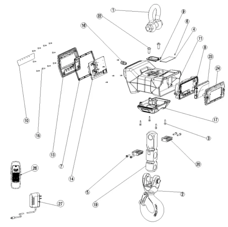
Exploded view
| No | NAME | SPEC | Q’TY | ||||||
| lion | 3ton | I 5ton | 10ton | ||||||
| 1 | Shackle | 5/8 | 7/8 | 1.1/4 | 1 | ||||
| 2 | Hook ass’y | 3T | 1 5T | 101 | 1 | ||||
| 3 | bolt | M5 x 20 | 4 | ||||||
| 4 | Spec plate | 95 x 40 | 1 | ||||||
| 5 | bolt | M6 x30 | 4 | ||||||
| 6 | Rivet | BLIND 2.5 x 6 | 2 | ||||||
| 7 | gasket | 200x120x3.5 | 1 | ||||||
| 8 | Battery—cover easy | TCBL | 1 | ||||||
| 9 | LC CAP | 6665×9 IT | I 055×9 3T | MN 5T | I 1211x911d 10T | 1 | |||
| 10 | Keypad | 169×29(Selection for LCD type or FND type) | 1 | ||||||
| 11 | TCB body | 215420×135(51) | I 10T | 1 | |||||
| 13 | Front panel | 201x121x20 | 1 | ||||||
| 14 | PCB asaY | LCD type or FND type | 1 | ||||||
| 15 | Screw | Flat head 144×16 | 10 | ||||||
| 16 | Code—stopper | PG7 | 2 | ||||||
| 17 | LC cover | 1T | 3T | 6T | 101 | 1 | |||
| 19 | Loedcell | CSS3-1T | CSS3-3T | CSS3-5T | CSS3-10T | 1 | |||
| 20 | LC BRK | 17 | 3T | 10T | 1 | ||||
| 22 | Wrench Boll | Round Head M10 x 25 | 2 | ||||||
| 23 | BATTERY PACK | TLP-100(LCD type) or TLP-200(FND type) | 1 | ||||||
| 24 | BATTERY COVER | LCD type or FND type | 2 | ||||||
| 25 | Power—cable | 02.5×400 | 1 | ||||||
| 26 | Remocon | IR-100 | 10 | ||||||
| 27 | Adaptor | LCD type : 51/.1A .Ø3.5 a FND type : 1241A , 03.5 | 1 | ||||||
Firmware Update
- Install the ‘MPLABX’
- Run ‘MPLAB X IDE’
- Connect the PICkit3 to PC
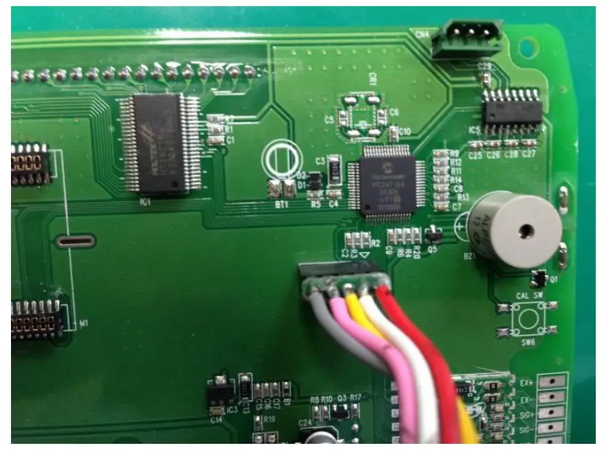
- Connect as shown in the picture below.
Aligned the RED wire and arrow mark of PCB, and then combines them.
- Select the HEX file (File – Import – Hex/ELF… (Prebuilt) File)
SEE ATTACHED VIDEO
1) Prebuilt Filename: Bring up the HEX file
2) Family: 16-bit MCUs (PIC24)
3) Device: PIC24FJ64GA306
4) Supported Debug Header: None
5) Hardware Tool: PICkit3
6) After the above setting, click NEXT ☞ NEXT ☞ Finish. - Set the Project Properties (File – Project Properties) SEE ATTACHED VIDEO
1) Click PICkit3 in Categories
2) Option categories: Memories to Program
3) Preserve Program Memory: Select
4) Preserve Program Memory Start (hex): 0x0800
5) Preserve Program Memory End (hex): 0x1FFF
6) After the above setting, click Apply.
7) Option categories: Power
8) Power target circuit from PICkit3: Select
9) After the above setting, click Apply ☞ OK. - Upgrade firmware SEE ATTACHED VIDEO
1) Click the Make and Program Device icon.
2) Confirm the complete message.
![]()


