Advanced Amplifiers AA-1M6G-30 Solid State RF Amplifier System
Product Information: Advanced Amplifiers Solid State RF Amplifier System AA-1M6G-30
The Advanced Amplifiers Solid State RF Amplifier System AA-1M6G-30 is a laboratory-grade product that is suitable for use in a wide range of industrial and scientific applications. It provides an operating frequency band of 1 MHz to 6.0 GHz, with a 30 Watt minimum power output and a minimum power gain of 45 dB. The equipment requires forced air cooling, and all air inlets and outlets must be kept free of blockages for optimum performance. The product is designed with a variety of safety features, including safety symbols to denote important information in the manual, protective earth terminals, and warnings about potential hazards. Users are also reminded to ensure proper grounding, to connect the RF output connector to a load before turning on the AC switch, and to turn off both AC and RF power before disconnecting output loads or other components.
Product Usage Instructions:
- Ensure that the product is properly grounded and connected to an uninterrupted safety ground with a power cord of sufficient size.
- Connect the RF output connector to a load before turning on the AC switch.
- Turn off both AC and RF power before disconnecting the output load or other components.
- Keep all air inlets and outlets clear of blockages for optimal performance.
- If repair or maintenance work is required, contact a factory authorized technician to avoid voiding any outstanding warranties.
Please also refer to the safety symbols and other important information in the manual before using the equipment.
SAFETY INSTRUCTIONS
BEFORE USING THIS EQUIPMENT
Read this manual and become familiar with safety markings and instructions. Inspect unit for any sign of external damage. Do not use this equipment if there is physical damage or missing parts. Verify the input AC voltage to the main power supply. For a system with a digital controller option – DO NOT USE OR CONNECT a PoE enabled ethernet switch to a system. Our digital controller does not support PoE connection and will cause permanent damages to a controller unit.
INTENDED USE
This product is intended for general laboratory use in a wide variety of industrial and scientific applications.
RF OUTPUT LOAD & PROPER GROUNDING REQUIRED
The RF output connector must be connected to a load before the AC switch is turned on. AC & RF power must be off before disconnecting the output load or other components. The main power source to the equipment must have an uninterrupted safety ground that has sufficient size to the power cord.
REPAIR & MAINTENANCE
All repair or maintenance work must be performed by a factory authorized technician in order to extend the operating life of this equipment and not to void any outstanding warranty.
FORCED AIR COOLING
This equipment requires forced air cooling. All air inlets and outlets must be cleared and free of blocking at all time. Insufficient air flow will result in damaged equipment.
SPECIFICATIONS
ELECTRICAL SPECIFICATIONS: 50Ω, 25°C
| Parameter | Specification | Notes | |
| Band | A | B | |
| Operating Frequency Band | 1 – 1000 MHz | 1 – 6 GHz | Band switching @ 15 mS Max |
| Power Output @ Psat | 30 Watt Min / 50 Watt Typ | CW or Pulse | |
| Power Gain | 45 dB Min | 0dBm or less for rated Pout | |
| Power Gain Flatness | 4.0 dB p-p Max | Constant input power | |
| Gain Adjustment Range | 20 dB Min | Local or remote | |
| Input Return Loss | -10 dB Max | ||
| 2-Tone Intermodulation (IMD) | -30 dBc Typ | 35dBm/Tone, Δ = 1MHz | |
| Harmonics | <-20 dBc Typ | At rated Pout | |
| Spurious | -60 dBc Max | Non-harmonics | |
| Operating Voltage | 100 – 240 VAC | 47 – 63 Hz | |
| Power Consumption | 500 Watt Max | At rated Pout | |
| Input Power Protection | +10 dBm Max1 | ||
| Load VSWR Protection | 6 : 1: Max2 | Foldback @ preset limit | |
| Sample Port (optional) | -40 dB | N-Female | |
- Units with optional digital monitor and control, for basic units <10 Sec without damage.
- Units with optional digital monitor and control, for basic units <1 minute at rated Pout.
ENVIRONMENTAL CHARACTERISTICS
| Parameter | Specification | Notes |
| Operating Ambient Temperature | 0 to +50 °C | |
| Storage Temperature | -40 to +85 °C | |
| Relative Humidity | up to 95 % | Non-condensing |
| Altitude | 3000 meters | |
| Shock & Vibration | Normal transport3 |
3 MIL Spec available for quotation.
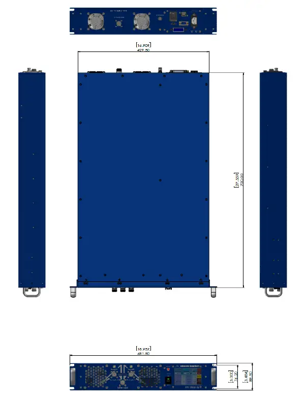
MECHANICAL SPECIFICATIONS
| Parameter | Specification | Notes |
| Dimensions W x H x D | 430 x 88 x 700 mm | 2U, excluding handles |
| Weight | 12 Kg. | |
| RF Connectors Input/Output/Sample | N-Female | Front or rear panel |
| Interface Connector | 9-Pin D-Sub | Rear panel |
| AC Power | IEC 60320-C14 | Or equivalent |
| Cooling | Built in Fan Cooling | Variable speed |
| OPTIONAL: Digital Monitor & Control (DMC) FWD, REV, VSWR, GAIN, ALC, V & I, TEMP, Optional Safety Interlock (INT) | Ethernet RJ-45 TCP/IP, RS422/485, USB Optional GPIB Interface Open=STBY/Short=RFON | IEEE rear panel BNC-F rear panel |
OPERATING INSTRUCTIONS & GENERAL INFORMATION
INTRODUCTION
Advanced Amplifiers is an amplifier equipment and services company supporting commercial and government organizations worldwide. Headquartered in San Diego, California, the company utilizes its global network of resources to effectively serve and support customer requirements. As a unique original equipment manufacturer of power amplifiers ranging from 10KHz to 40GHz with various output power levels for CW & pulse testing applications, we can also fully support custom designs and manufacturing requirements for both small and large volume procurements. We bring decades of combined experience in the RF field for numerous applications including and not limited to, EMI/EMC, communications, and various commercial and industry standards. With our in-house capabilities and fully equipped testing facilities, Advanced Amplifiers is committed to provide the best in RF products with industry leading quality and lead times
INCOMING INSPECTION
Inspect unit for any sign of external damage. Do not use this equipment if there is physical damage or missing parts. Inspect all front and rear panel connectors for damage. Inspect fans and their airways for any damage or blockings. For a unit with a digital controller option, the USB and ethernet interface and commands list is in the second part of the manual.
RF & AC CABLE CONNECTION
RF Input and Output connectors are outlined in the specifications table. Use the standard AC cable that was supplied by the manufacturer or higher power rating cables than the manual specifies. Refer to the front and rear panel description page for the location of RF and AC connectors. For a system with a digital controller option – DO NOT USE OR CONNECT a PoE enabled ethernet switch to a system. Our digital controller does not support PoE connection and will cause permanent damages to a controller unit.
RF TURN ON PROCEDURE
Connect RF input to an RF Pulse Generator and Gating signal. Connect a suitable load for the power rated and continuous operation to the output connector. Turn on the AC switch, display will show STANDBY. Optionally, connect the unit to a digital control Software or Ethernet connection. Set the RF generator to nominal 0dBm and set the desired frequency in the specified range. Select Gain or ALC and set to the desirable output power level then press the ONLINE button. Use the front panel LCD gain adjust or the remote function to adjust the output power on the power meter and the LCD screen to desired levels. Refer to Appendix-1 for detailed operating instructions of the local and remote controller.
RF TURN OFF PROCEDURE
Decrease the RF drive from the RF generator to below -20dBm and press STANDBY on the LCD or via the control software. Turn off AC switch on the front panel. Disconnect any unnecessary cable connections.
DECLARATION OF CE CONFORMITY
We, Advanced Amplifiers Corp, declare under our sole responsibility that the product to which this declaration relates is in conformity with the following standard(s) or other normative document(s):
Council Directive 98/37/EC on the Safety of Machinery Directive
Council Directive 2014/35/EC on Low Voltage Equipment Safety
LIMITED WARRANTY
Advanced Amplifiers warrants that goods delivered hereunder, at the time of delivery, will be free from defects in workmanship and material and will conform to the requirements of the purchase order. Seller’s liability hereunder shall be limited to the repair or replacement of defective goods F.O.B. factory of which Seller is modified in writing by Buyer within three (3) years following delivery thereof to Buyer, and in no event will Seller be liable for incidental, special or consequential damages. (Note: One (1) year warranty for moving parts such as fans and power supplies). The foregoing warranty is in lieu of all other warranties express or implied (except as to title), including any implied warranty of merchantability or suitability for purpose or against infringement.
CONTACT INFORMATION
Please send all inquiries to:
Advanced Amplifiers
10401 Roselle Street
San Diego, CA 92121
WEB: WWW.ADVANCEDAMPLIFIERS.COM
EMAIL: [email protected]M
COPYRIGHT & TRADEMARKS
Copyright 2022 Advanced Amplifiers, All rights reserved. All other trademarks and brand names are the property of their respective proprietors.
FRONT & REAR PANEL DESCRIPTIONS
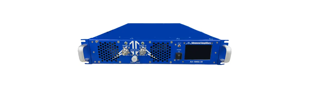
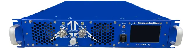
FRONT PANEL VIEW

| No. | Title | Function |
| 1 | RF SAMPLE A | N Female, RF SAMPLE Connector. SAMPLE PORT MUST BE TERMINATED AT ALL TIME |
| 2 | RF SAMPLE B | N Female, RF SAMPLE Connector. SAMPLE PORT MUST BE TERMINATED AT ALL TIME |
| 3 | 0dBm INPUT | N Female, 0dBm INPUT Connector. |
| 4 | FAULT LED | System Fault LED: Turn ON an LED when Over-Temp, Ext. Shutdown. |
| 5 | POWER SWITCH | System Power Switch. |
| 6 | LCD DISPLAY | 4” Touch screen LCD Display, System Control LCD Panel. |
REAR PANEL VIEW
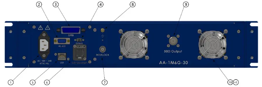
| No. | Title | Function | |
| 1 | AC POWER CONNECTOR | AC Power Input 100 ~ 240VAC, 47/63Hz, IEC60320-14 Connector. | |
|
2 |
RS-422 | System RS-422 Communication / Gating Signal Female 9-Pin D-Sub Connector. | |
| P1 TX- | P6 N/C | ||
| P2 TX+ | P7 N/C | ||
| P3 RX+ | P8 N/C | ||
| P4 RX- | P9 N/C | ||
| P5 GND (RS-422) | |||
| 3 | GPIB | IEEE-488 GPIB Interface Connector, Female. | |
| 4 | DEBUG | System Controller Debugging Female Connector. Port access requires factory authorization | |
| 5 | USB | USB Communication Connector, Type A Female. | |
|
6 |
ETHERNET | Ethernet Communication Female Connector, RJ-45. For a system with a digital controller option – DO NOT USE OR CONNECT a PoE enabled ethernet switch to a system. Our digital controller does not support PoE connection and will cause permanent damages to a controller unit. | |
| 7 | INTERLOCK | BNC Female, Safety Interlock Connector Interlock Close Circuit : Normal operation Interlock Open Circuit : RF Off operation | |
| 8 | GND | Frame Ground. | |
| 9 | 50Ω OUTPUT | N Female, 50Ω OUTPUT Connector. | |
| 10 | Cooling FAN | System Outlet Cooling FAN. | |
SYSTEM OUTLINE VIEW