![]()
KR5 UE Relay
User Configuration & Monitoring Guide
Revision 0.51
July 2020
© Copyright 2020 KUMU NETWORKS INC. ALL RIGHTS RESERVED.
Legal Notice
This guide contains proprietary data subject to copyright, patent and other security. No whole or portion of this document may be distributed, duplicated or disclosed, without the expressed, earlier, written authorization of Kumu Networks Inc. Use of this guide or the data contained in this for reasons other than those for which it is intended is entirely prohibited.
Data provided by Kumu Networks Inc. is accepted to be correct. However, no duty is expected by Kumu Networks Inc. for the utilization thereof nor for the privileges of outsiders which might be affected in any capacity by its use.
Any representation(s) in this guide concerning execution of Kumu Networks Inc. product(s) are for instructive purposes only and are not warranties, either communicated or inferred.
This guide may contain imperfections, exclusions or errors. No guarantee is conceded nor risk accepted in connection thereof. Kumu Networks Inc. holds the right, without earlier notice or risk, to make changes to the hardware or this document.
Overview
The document is a User Configuration and Monitoring Guide for the Kumu KR5 UE Relay.
The following SKU variants are currently supported:
| SKU | Access LTE Band | Backhaul LTE Band Combinations |
| KR5192 | B2 | B2 + B12/13/17 |
| KR5181 | B3 | B3 + B8/20/28 |
| KR5261 | B7 | B7 + B8/20/28 |
This product is intended for use by a qualified network operator in compliance with local safety regulations and building codes in the country of installation.
Product Support: For Technical Support, email [email protected]
Functionality
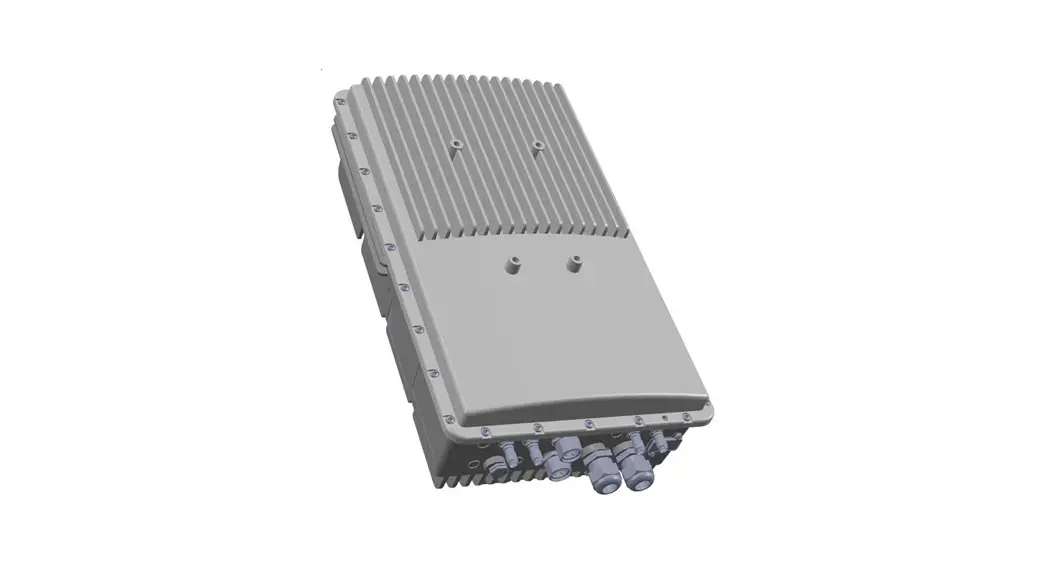
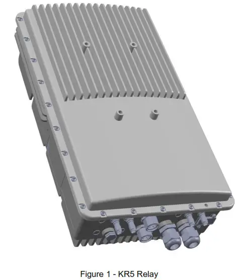
Kumu Networks’ KR5 Full Duplex Self-Backhaul LTE UE Relay (Figure 1) enables small cell LTE eNodeB’s to backhaul to an LTE macro base-station with the same access frequencies used by both the small cell and the macro network.
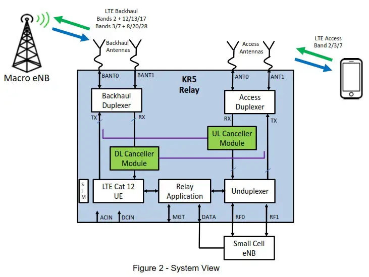
The Relay accomplishes full-duplex operation by utilizing Kumu Networks’ proprietary SelfInterference Canceller technology to suppress transmitter interference into the receive radios in real-time, such that both the Uplink and Downlink radios can be operational in the same channel at all times.
By using Full Duplex wireless backhaul, operators not only reduce frequency planning complexity but also improve spectral efficiency through channel reuse. The KR5 Relay is easy to install in a matter of minutes. It eliminates the cost of wired backhaul and minimizes operational costs by providing an easy to use network management interface.
The KR5 Relay is designed to be paired with an external eNodeB. The Relay backhauls the eNodeB to another base station over the same access frequencies used by both the eNodeB and the macro network.
Features
- Simultaneous use of same channel for access and backhaul (Full-Duplex)
- SKU variants for different LTE bands
- Integrated Cat 12 LTE UE for maximum throughput on backhaul link
- Up to 2CC 30MHz Carrier Aggregation with low-band LTE for improved backhaul coverage
- Works with any LTE small cell
- eNodeB MIMO support up to 2Tx / 2Rx
- eNodeB transmit power support up to 5W per port (+37dBm)
- Transmit noise suppression in receive channel down to -85dBm with Self-Interference Cancellation
- Real-time tuning so cancellation is maintained even in presence of wireless channel variations
Interfaces
| Interface | Connector | Purpose |
| BANT0 | Nex10 | Backhaul TX/RX RF I/O |
| BANT1 | Nex10 | Backhaul RX only RF Input |
| ANT0 | Nex10 | Access TX/RX RF I/O |
| ANT1 | Nex10 | Access TX/RX RF I/O |
| RF0 | Nex10 | TX/RX RF I/O to eNB |
| RF1 | Nex10 | TX/RX RF I/O to eNB |
| ETH1 | RJ-45 | Ethernet I/O to eNB/Config |
| ETH2 | SFP/RJ-45 | Ethernet I/O to eNB/Config |
| ACIN | Custom | 90V-240VAC power supply |
| DCIN | Custom | -48VDC |
Electrical Specifications
| Specification | Description |
| LTE Bandwidths | 5,10 & 20 MHz |
| Backhaul Carrier Aggregation | 2CC Interband up to 30MHz |
| eNodeB Tx power | Up to +37 dBm (per port) |
| eNodeB MIMO | Up to 2Tx / 2Rx |
| UE Tx power | Up to +23dBm |
| UE MIMO | 1Tx / 2Rx |
| Max DL Throughput (PHY) | 150Mbps (20MHz) 225Mbps (20 + 10 MHz) |
| Antenna Isolation (Backhaul – Access) | >45dB required |
| Remote Operations and Maintenance | NetConf |
| AC Input | 150W 90-254 V~ (AC), 47-63 Hz |
| DC Input | -48V DC |
Environmental Specifications
| Specification | Description |
| Operating temperature | -40° to 55° C |
| Operating humidity | 5% – 100% non-condensing |
| Ingress protection (rain/dust) | IP65 |
Physical Specifications
| Specification | Description |
| Size | 18” x 10.6” x 5.8” |
| Weight | 14.8 kg (without bracket) |
| Mounting | Pole or wall mounted |
| Safety | UL 62368 |
| Hazardous materials | RoHS |
| Certifications | FCC Part 15 (US) FCC Part 24 (US) FCC Part 27 (US) |
Getting Started
Setup
- Connect a laptop to the KR5 Relay either via a switch or directly to the ETH1 (preferred) or ETH2 port on the relay.
- Set the laptop ethernet port to DHCP (this is typically already the case)
- Open a browser and enter http://192.168.100.1
- Accept the security warning due to the self signed certificate.
- Enter the administrator username & password. Default username for relay is Administrator and password is Administrator
You should be greeted by the Basic Status page as shown in Figure 3.
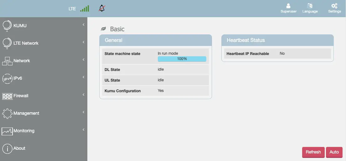 Figure 3 KR5 Relay GUI Top Level Menu
Configuring the Relay
RF Configuration
![]() IMPORTANT: The cancellation modules are calibrated based on the values in the this screen. Changing the values in these fields will cause the relay to restart and recalibrate.
IMPORTANT: The cancellation modules are calibrated based on the values in the this screen. Changing the values in these fields will cause the relay to restart and recalibrate.
Select KUMU -> Configuration to get to the Kumu Configuration screen as shown in Figure 4
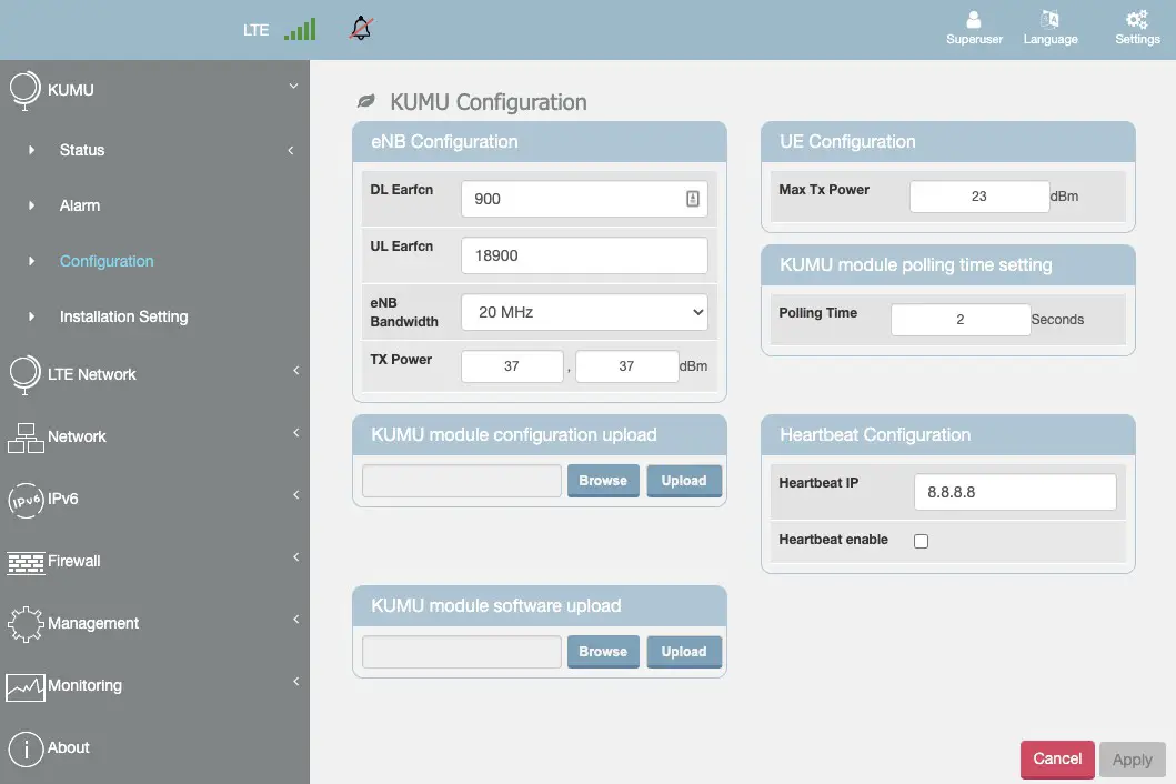
Figure 4 – KUMU Configuration Screen
Mandatory Settings
Set the DL Earfcn channel number that will be used by the small cell. If the small cell supports multiple bands, enter the channel number for the Band 2 channel.
Set the UL Earfcn channel number that will be used by the small cell. If the small cell supports multiple bands, enter the channel number for the Band 2 channel.
Setup eNB bandwidth. If the small cell supports multiple bands, enter the value from Band 2. Default is 20MHz. Allowed values are 5MHz,10MHz or 20MHz
Setup TX Power for each of the eNodeB ports. Default/Max is 37 dBm each.
Setup Max TX Power for the UE. Default/Max is 23 dBm.
Other Settings
The Kumu Module Configuration Upload should not be used by vendor unless instructed by Kumu personnel.
Leave KUMU module polling time setting at 2s unless instructed by Kumu
Heartbeat Configuration can be used to regularly ping an IP address to confirm connectivity. If desired:
Set Heartbeat IP to the IP address of the machine to be pinged Set Heartbeat enable as appropriate to enable/disable Finally, select Apply to save the settings. The backhaul connection may be temporarily dropped while the new settings are applied.
Site Survey / Setup
![]() IMPORTANT: Changing values on this screen will result in the backhaul relaying re-initializing during which the backhaul connection will be lost.
IMPORTANT: Changing values on this screen will result in the backhaul relaying re-initializing during which the backhaul connection will be lost.
Select KUMU -> Installation Setting to get to the installation screen as shown in Figure 5
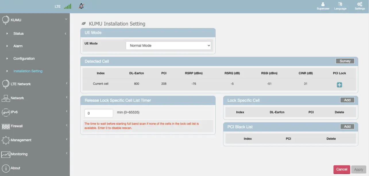 Figure 5 – Installation Screen
This screen is used for antenna alignment. Set UE Mode = Scan Mode and Apply.
Monitor RSRP/RSRQ/CINR while aligning antennas for the best quality signal. Note that in dynamic environments these may change frequently Once antennas are aligned, change UE Mode = Normal Mode and Apply.
PCI Lock can be used to lock Donor Cell if necessary. This should only be used when absolutely necessary as it will prevent the relay from roaming to other cells if the locked cell goes down, or changes it’s PCI.
PCI Black List can be also used to Black List specific PCI’s if necessary. In rare cases it may be needed to black list the local small cell to prevent the relay from attempting to attach to it.
Network Configuration
Select Network -> WAN Setting for network configurations.
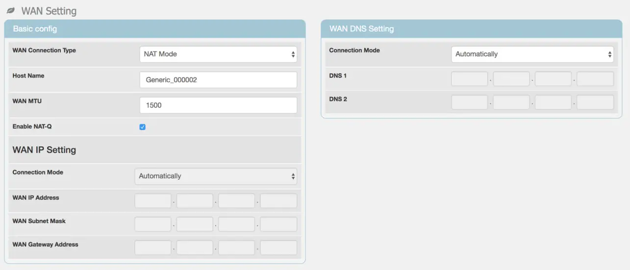 WAN MTU may need to be configured based on eNodeB preferences. Default value for WAN MTU is 1500. Other settings should not be changed unless directed by Kumu personnel
Management
User Name & Password
Select Management -> Account to change default user name or password for the Relay.
Device Log
The relay supports sending syslog messages to a remote server.
Select Management -> Device Log to manage device log location and contents. Default setting is that device does not generate logs.
To enable syslog logging:
- Change Syslog Target to Remote
- Enter the IP address of the syslog server
- Set the Severity level as appropriate. It is not recommended to set this any higher than (5) Informational for regular operation.
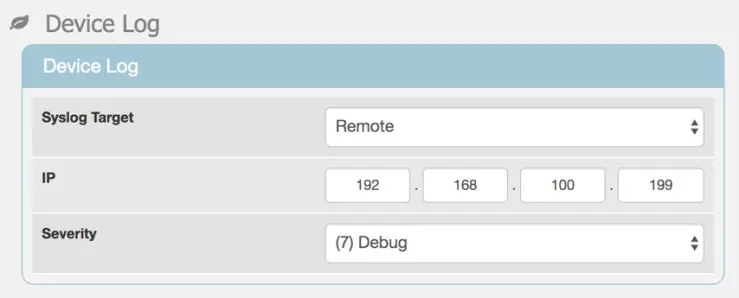
Figure 6 – Device Log Settings
Factory Reset
Select Management -> Restore Default to reset Relay back to Factory Default.
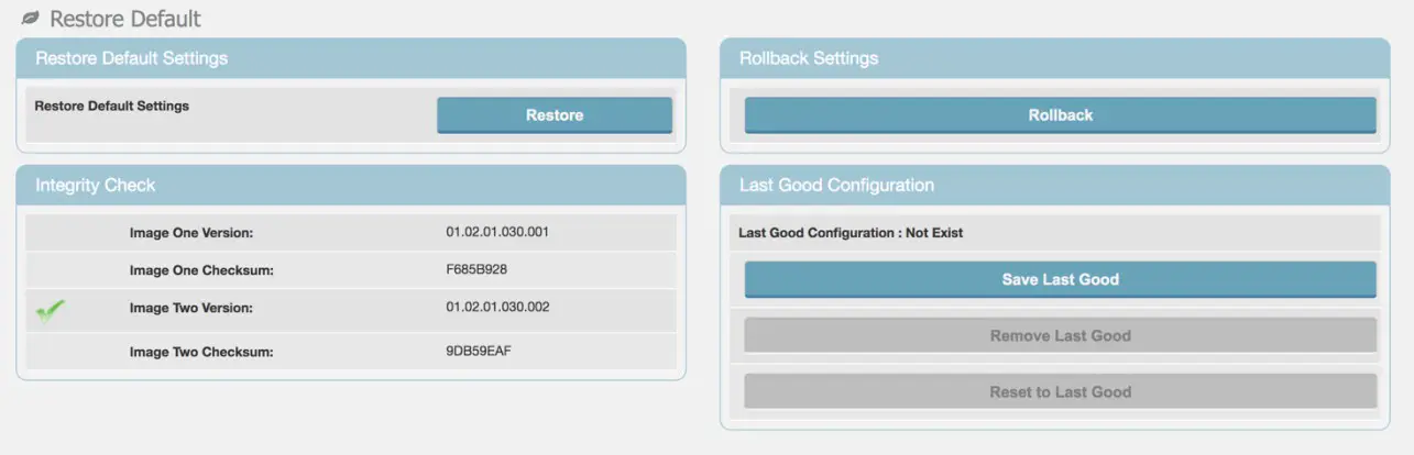
Figure 7 – Restore Default Screen
Software Upgrade / Config Backup Restore
Select Management -> Software to update the Relay software. This screen also shows the current Relay software version.
Select Browse to open a dialog and select a new software installation file (*.ipk).
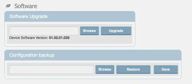 Figure 8 – Software Management Screen
This screen also offers the option to backup/restore the relay configuration.
To Backup the Configuration:
Choose Save to download a backup copy of the relay configuration. Enter a passphrase that will be used to secure the image.
To Restore the Configuration:
Choose Browse to select a backup file for upload, and then Restore to upload to relay. Enter the passphrase that was used to secure the image
About
The KR5 Relay About GUI provides useful information about metrics and status of the Relay as shown in Figure 9.
Select About from the main menu to check Relay device information including IMEI, Firmware version and LTE Bands supported.
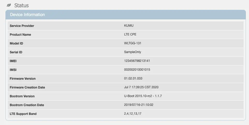 Figure 9 – About Screen
Performance Status
Kumu Cancellation Status
Select Kumu -> Basic for basic status information of the Kumu cancellation technology as shown in Figure 10.
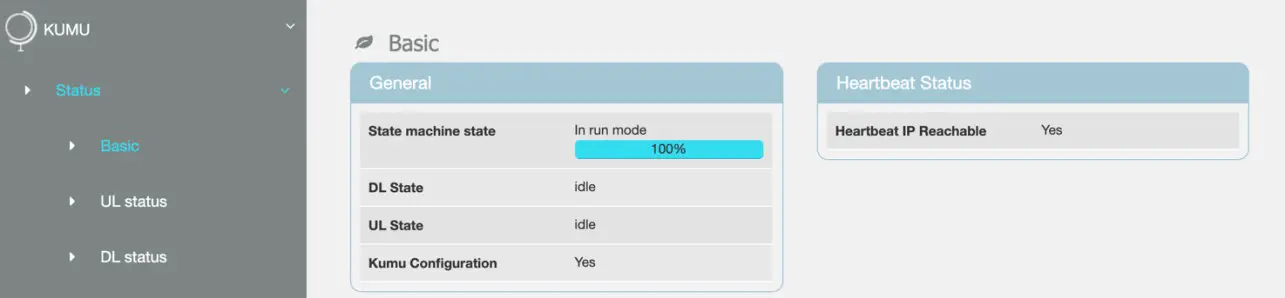 Figure 10 – Kumu Basic Status Screen
State Machine State will enumerate through a number of states on power-up, or during config changes. During normal operation it will show “in run mode” and 100%. During normal operation both DL State and UL State will show “idle”. At all times the Kumu Configuration will show “Yes”. If any of the above do not go to the intended state within 10 minutes, check the Alarms screen for more information. Heartbeat IP Reachable is user indicate that the configured Heartbeat IP can be contacted and is useful for confirming a valid IP connection. Select Kumu -> UL Status or KUMU -> DL Status from the main menu to check detailed cancellation status, e.g. if Relay is Calibrated or is actively cancelling self-interference. This screen also confirms Relay RF setting information.
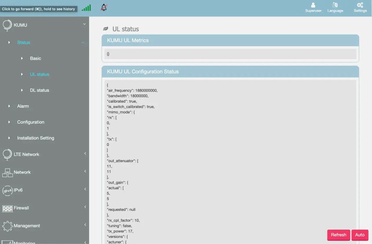 Figure 11 – Kumu Advanced Status Screen
LTE Status
Select LTE Network -> Status -> Basic to check connectivity status, LTE information and Uplink & Downlink status of the backhaul link as shown in Figure 12.
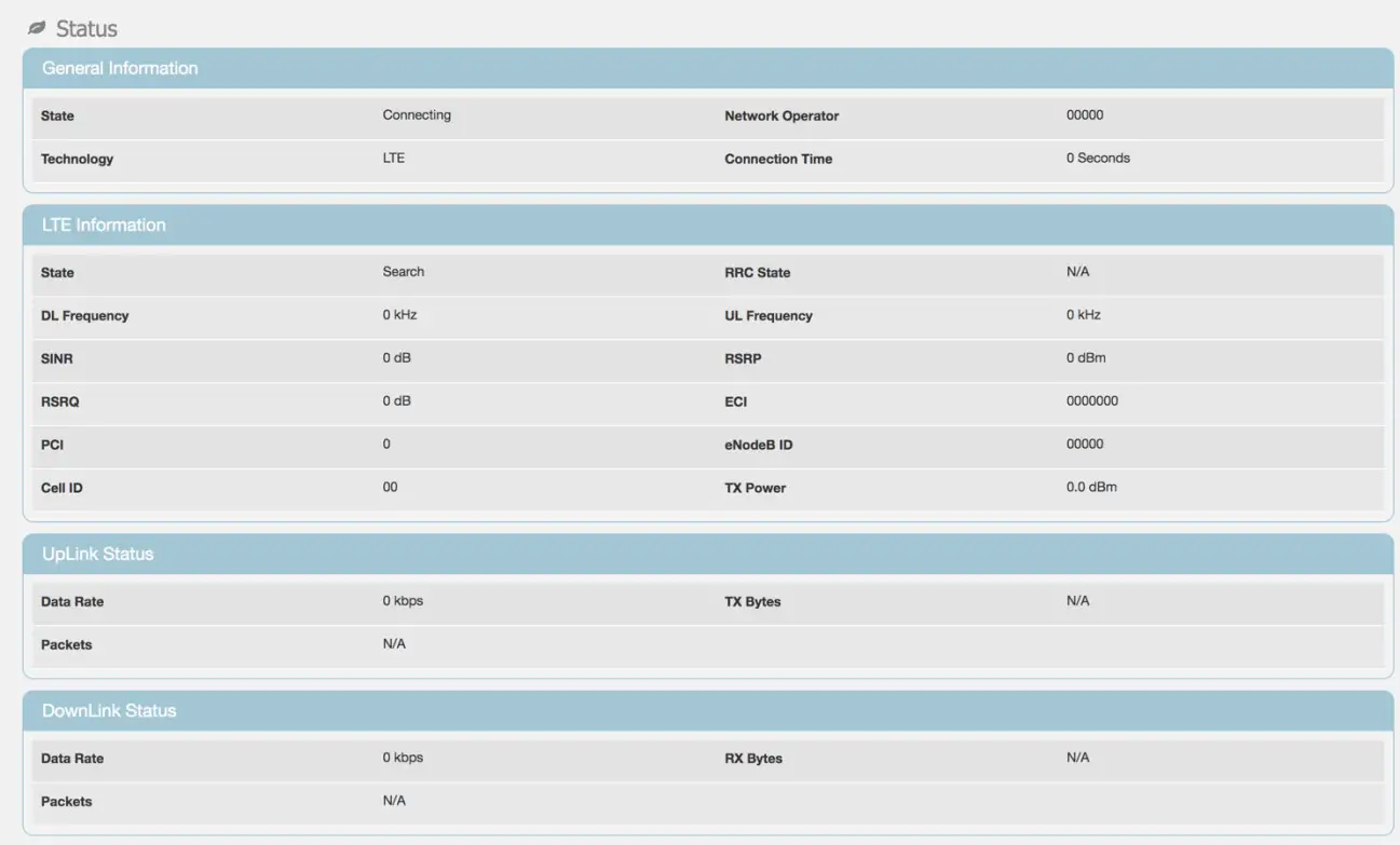
Figure 12 – LTE Basic Status Screen
Select LTE Network -> Status -> Advanced to check LTE TX (PUSCH) and LTE RX (RSRP, SINR) information.
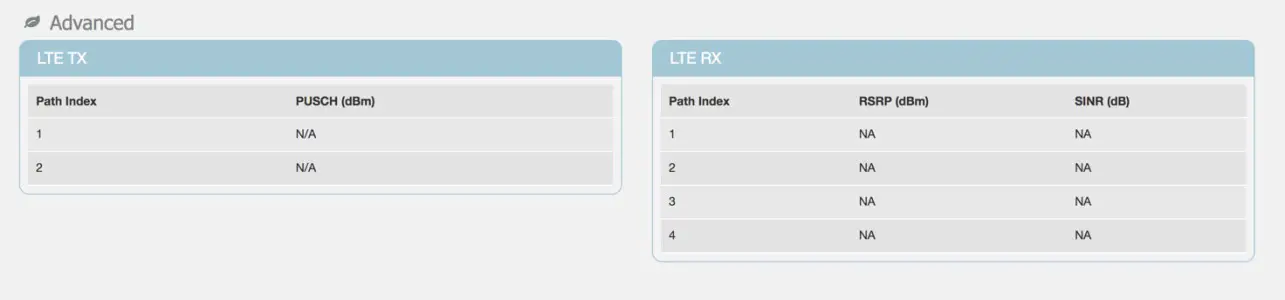 Figure 13 – LTE Advanced Status Screen
Select LTE Network -> Status -> PDN to check Serving Cell information.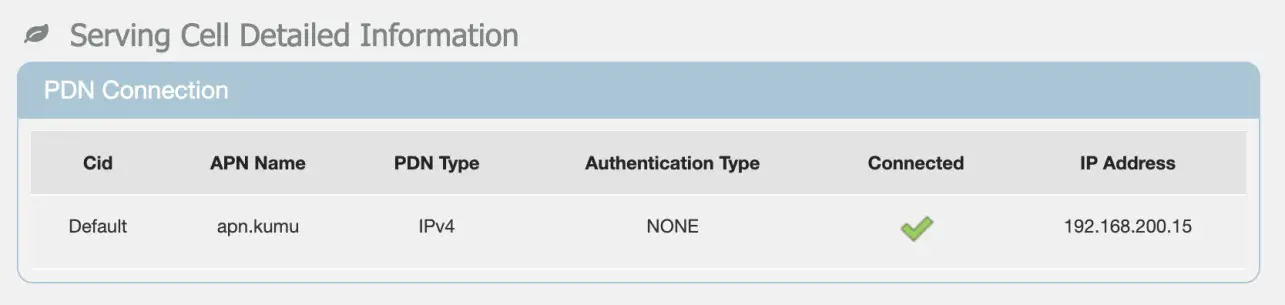 Figure 14 – LTE Serving Cell Screen
Network Status
Select Network -> Status to check details on LAN and WAN configurations, as shown in Figure 15
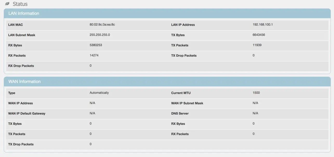 Figure 15 – Network Status Screen
Select IPv6 -> Status to check IPv6 LAN address configuration.
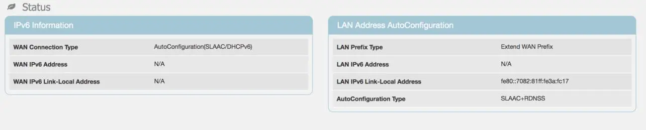 Figure 16 – IPv6 Status Screen
Advanced Settings
The KR5 Relay GUI allows advanced settings to be configured. These settings should only be changed by qualified operators if required and are not necessary to configure for most normal installations.
LTE Settings
Band Selection
Select LTE Network -> Cell Selection for advanced configurations including to limit bands used for backhaul. Use the Band options to enable/disable bands on the backhaul link. Note that Band 4 is not supported by the current hardware and should not be enabled.
Other settings should not be used except as directed by Kumu personnel.
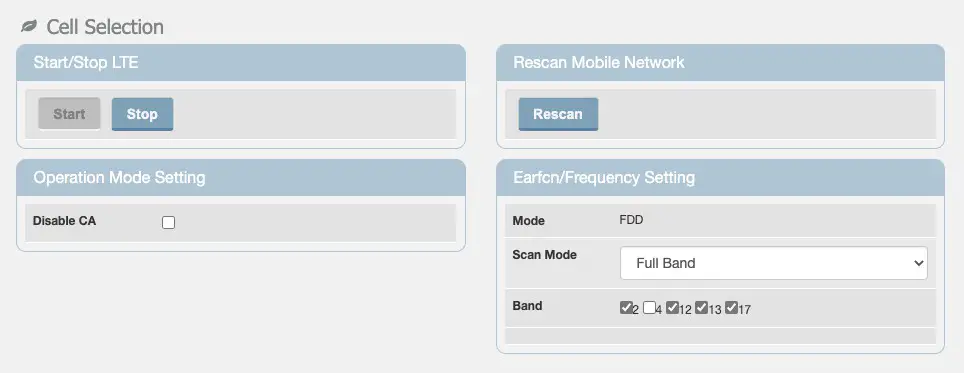
Figure 17 – Cell Selection Screen
Default PDN
Select LTE Network -> Default PDN for advanced Packet Data Network (PDN) connection parameters.
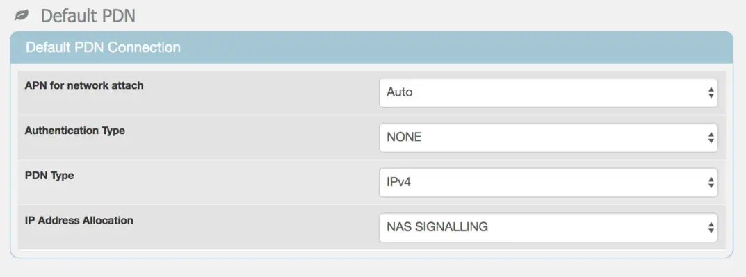
Figure 18 – Default PDN Screen
Multiple PDN Select LTE Network -> Multiple PDN if required for multiple Packet Data Network (PDN) connections
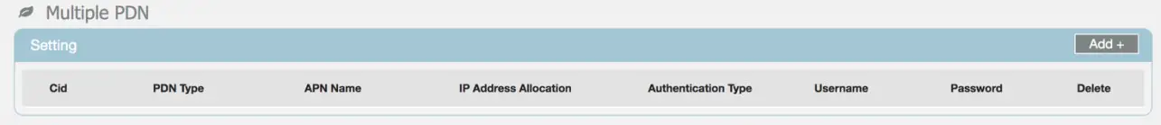
Figure 19 – Multiple PDN Screen
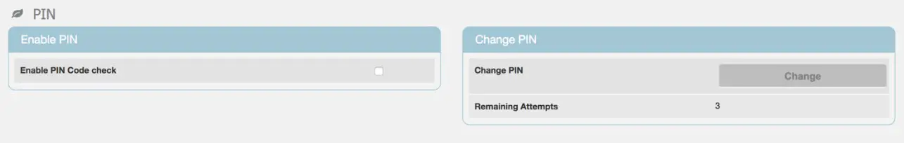
SIM Card PIN (CPIN) Select LTE Network -> PIN to enable PIN code check for SIM card or change the PIN. This is not a common setting as most networks no longer use SIM cards with PIN.
Network Settings
Select Network -> LAN Setting to setup LAN IP address or enable/disable the DHCP server. The LAN Settings should NOT be changed without consulting Kumu technical support.
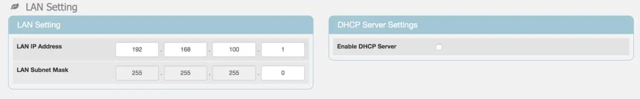
Figure 20 – LAN Settings Screen
Select Network -> Port Forwarding to setup port forwarding. These are not necessary for normal operation.
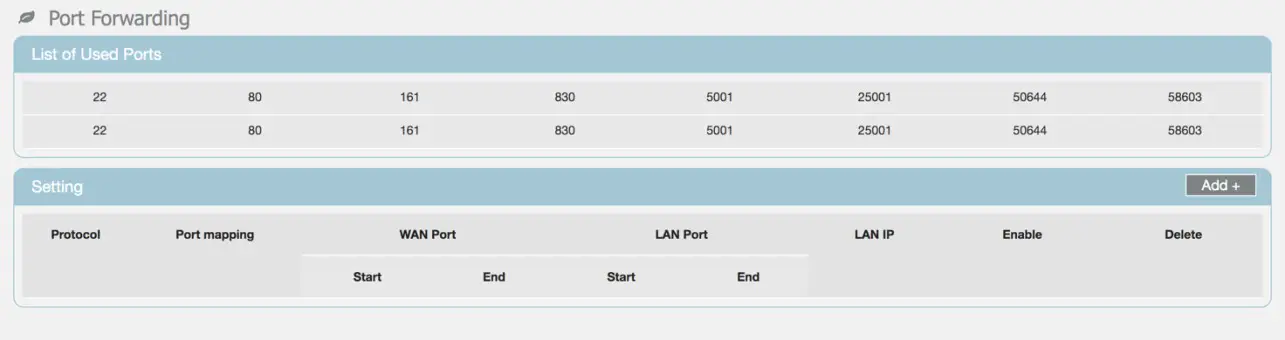 Figure 21 – Port Forwarding Screen
Select Network -> Port Trigger to setup port triggering. These are not necessary for normal operation
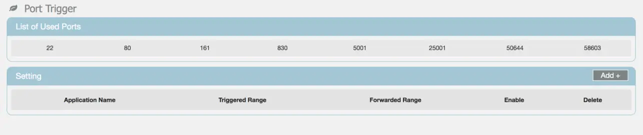 Figure 22 – Port Trigger Screen
IPv6 Settings
Select IPv6 -> Settings to setup Internet connection type and IPv6 LAN address settings.
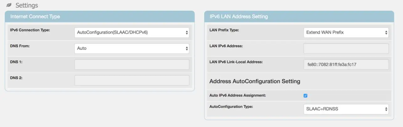
Figure 23 – IPv6 Settings Screen
Firewall Settings
Select Firewall -> Basic to enable/disable firewall and basic firewall settings.
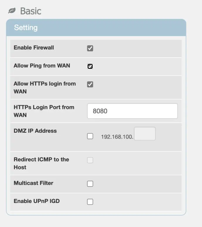
Figure 24 – Firewall Basic Settings Screen
Select Firewall -> Access Restriction to add access restrictions to the Relay. Figure 25 – Firewall Access Restrictions Screen
Monitoring the Relay
Status
Select Monitoring -> Status for information on CPU Utilization, Memory Utilization, Uplink and Downlink data rates and system information like the last restart reason.
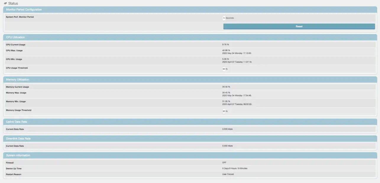 Figure 26 – Monitoring Status Screen
iPerf Utility
Select Monitoring -> iPerf to setup and perform uplink and downlink speed test. Note that due to the performance limitations of the onboard CPU to run the iPerf application you may not be able to see full performance. Use an external speedtest tools (ex. Speedtest.net, or testmy.net) to see true backhaul performance.
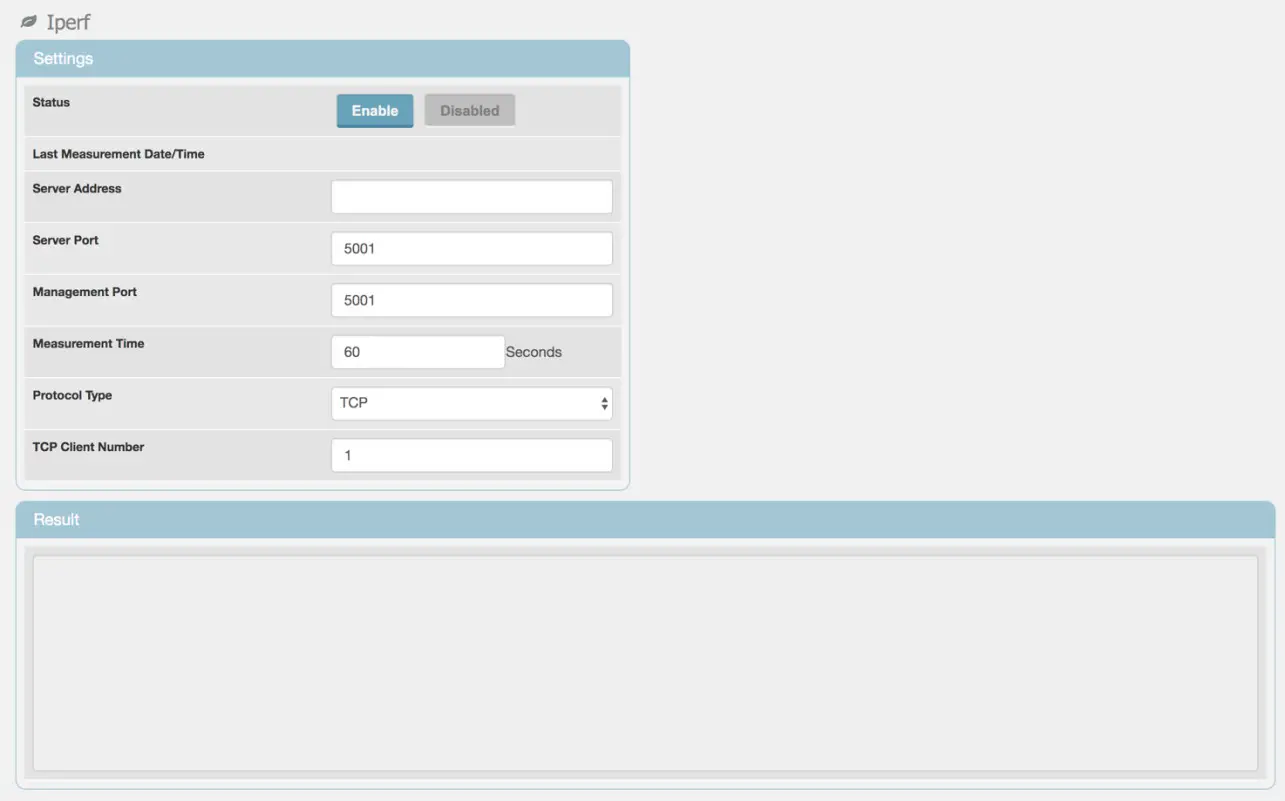
Figure 27 – Iperf Screen
Diagnostic Tools
Select Monitoring -> Diagnostic Tools to setup diagnostics and observe diagnostic metrics including ping timings and counts or traceout. Ping helps verify if system is connected to the internet or other devices while traceroute can be used to troubleshoot connection routing. Please consult your networking support engineer for use of these tools.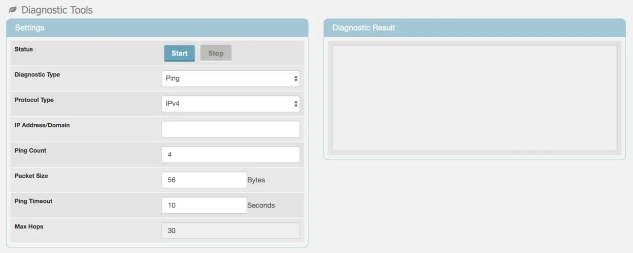 Figure 28 – Ping / Traceroute Screen
Status LED’s
There are two LEDs on the side of the relay that indicate the state of the relay, as shown in Table 1.
Table 1 – LED Status and Recommended Action
| Red LED | Green LED | Relay Status | Action |
| Flashing | Off | Booting, not connected | Wait 5 — 10 minutes for system to complete boot process. |
| Solid | Off | Error, not connected | Check Kumu -> Alarms |
| Off | Solid | Connected | No action required |
| Off | Off | Not connected | Check power to relay |
System Alarms
Check Kumu -> Alarms to view current alarms, and suggested next steps.
If State = True then this is an active alarm. If State = False then the alarm condition has been cleared.
The Message will give details on the alarm and possible next steps.
Last-set indicates how long since this alarm was last activated.
Last-clear indicates how long since this alarm was last cleared.
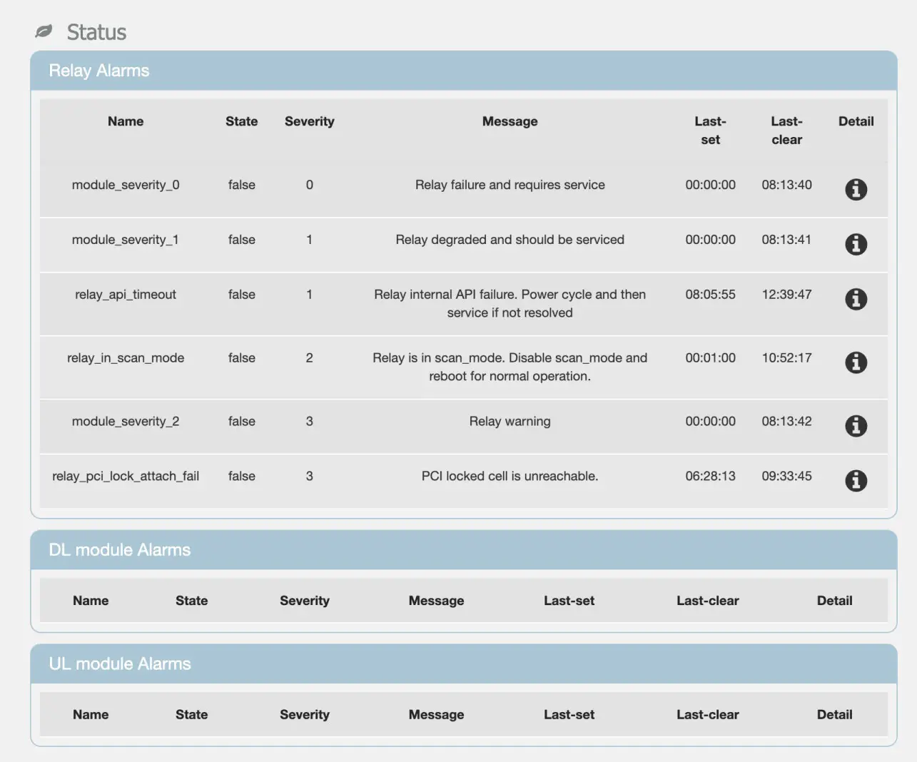
Figure 29 – Alarms Screen
Note: In V33 of the Relay software many alarms will be shown with State=False that have never been activated. These alarms can be ignored.


