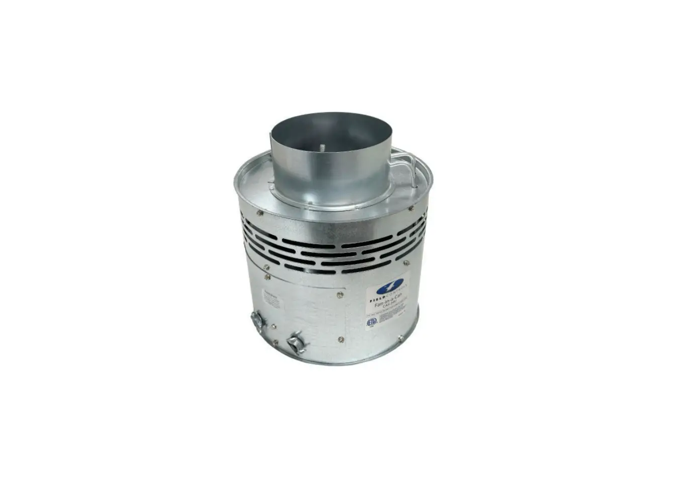
FIELD CONTROLS CAS-34U Combustion Air System
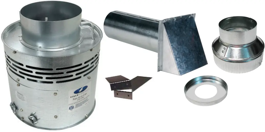
ITEMS INCLUDED IN KIT:
- 1 – Motorized Blower
- 2 – Mounting Brackets
- 1 – 4″ x 6″ Pipe Increaser Fitting
- 1 – Instruction Sheet
- 1 – 4” Intake Air Hood
- 1 – 6” Orifi ce Ring
![]() WARNING
WARNING
CONNECTIONS TO MULTIPLE APPLIANCES MUST FOLLOW INSTALLATION INSTRUCTION WIRING DIAGRAMS.
READ THESE INSTRUCTIONS CAREFULLY AND COMPLETELY BEFORE PROCEEDING WITH THE INSTALLATION.
This device MUST be installed by a qualified agency in accordance with the manufacturer’s installation instructions. The definition of
a qualified agency is: any individual, firm, corporation or company which either in person or through a representative is engaged
in, and is responsible for, the installation and operation of HVAC appliances, who is experienced in such work, familiar with all the
precautions required, and has complied with all the requirements of the authority having jurisdiction.
The model CAS-34U is a combustion air system based on the CAS-3 and CAS-4 units. This product is designed for use with any oil, natural gas, or LP burning furnace, water heater, or boiler. The CAS-34U is a universal combustion air system that will operate with 120VAC or 24VAC control systems. The CAS-34U may also be used in combination with a 30mV standing pilot gas water heater with the use of an additional CK-20 series control kit. Additional 120V or 24V controlled appliances may also be served by the CAS-34U with the addition of one CAC120 or CAC-24 control kit (per each additional appliance, see note*.) The CAS-34U mechanically draws air into the structure and disperses it near the combustion air intake of an appliance. Refer to Table 1 for guidance in set up of the CAS-34U based on the size and length of the connecting ductwork and the input rating of the appliance(s).
*NOTE: This product will meet the NFPA-31 standard. Please note that there are differences in construction, operation and installation of this CAS as compared to legacy product.
SPECIFICATIONS
SPECIFICATIONS | |
Internal motor | 120VAC, 0.8A, 60Hz. Maximum loaded speed 2600 RPM |
L1 terminal | Idle current at 120VAC: 18.25mA (no call for heat, no signal on M terminal) |
| M terminal input signal | 120VAC, 5mA. Trigger voltage above 89.6VAC |
Appliance: Oil, 120VAC nominal (voltage selection switch in the120VAC position) | |
| T1 | Minimum operating voltage 89.6VAC, drop out voltage 58.4VAC |
T2 | Must be connected to neutral in reference to T1 supply voltage |
| T1 & T3 | Maximum Full Load Conditions: 120VAC, 60Hz, FLA 9.8A, LRA 58.8A (1/2HP) |
Appliance: Gas, 24VAC (voltage selection switch in the 24VAC position) | |
| T1 | Minimum operating voltage 18.75VAC, drop out voltage 13.8VAC |
T2 | Must be connected to 24VAC common in reference to T1 supply voltage |
| T1 & T3 | Full load conditions 3.3A up to 5A. Typical gas appliance 3.3A or less, Class II |
Voltage Selection Switch | Sets the desired voltage on the T1 terminal |
GENERAL SYSTEM OPERATION
- The thermostat (wall thermostat or aquastat) calls for heat which activates the CAS-34U unit. After the CAS-34U fan has come up to speed and air flow into the CAS-34U inlet is established, an internal air pressure switch closes and completes the circuit to allow the burner to fire. If the appliance is power vented, the venter and CAS-34U activate simultaneously. After the CAS-34U and power venter have come up to speed, a pressure switch in the power venter control also closes and allows the appliance to fire.
- After the heating requirement has been satisfied, the thermostat circuit will open and deactivate the burner and CAS-34U unit.
- For power vented systems with a post purge device, the power venter and CAS-34U operate for a period of time after the burner has shut off to purge remaining flue gases from the vent system.
![]() CAUTION
CAUTION
This device must be installed by a qualified installer in accordance with the manufacturer’s installation instructions.
SIZING AND SETUP
Table 1 shows the maximum equivalent length and size of duct pipe that should be used when installing the CAS-34U system. Using this table will help ensure that the proper amount of air is drawn into the structure as needed by the appliance. Follow the guidelines below to properly size and set up the CAS-34U.
- Determine the maximum input firing rate of the appliance, or the maximum total firing rate of multiple appliances that will be used.
- Position the motorized CAS-34U unit according to the guidelines in the “Installation” section.
- Determine where the intake air hood will be located based on the recommendations in the “Installation” section.
- The CAS-34U is equipped with a High/Low motor speed control switch. When calculating the maximum equivalent feet, determine which speed is appropriate for the application. (Refer to Tables 1 and 2)
- Calculate the total equivalent length of duct pipe including elbows and fittings needed to connect the CAS-34U unit to the intake air hood. (Refer to Table 1)
- On Table 1, locate the point that corresponds to the correct combination of firing rate and duct size.
TOTAL INPUT OF APPLIANCE | MAXIMUM EQUIVALENT FEET OF INSTALLATION | ||||||
Oil (gph) | Gas (BTU) | 6” Duct And 6” Intake Air Hood | 4” Duct And 4” Intake Air Hood | 4″ Duct And Hood w/ Orifice Ring | |||
HI | LOW | HI | LOW | HI | LOW | ||
| 0.50 – 0.75 | 50,000-100,000 | 300 | 300 | 300 | 300 | 300 | 300 |
0.90 | 125,000 | 300 | 300 | 300 | 220 | 300 | 220 |
| 1.00 | 150,000 | 300 | 300 | 232 | 118 | 174 | 108 |
1.25 | 175,000 | 300 | 300 | 152 | 63 | 99 | 48 |
| 1.35 | 200,000 | 300 | 300 | 102 | 32 | 52 | 14 |
1.55 | 225,000 | 300 | 239 | 68 | 13 | 20 | |
| 1.75 | 250,000 | 300 | 150 | 45 | |||
2.00 | 300,000 | 300 | 53 | 16 | |||
2.50 | 350,000 | 193 | 8 | ||||
2.75 | 400,000 | 109 | |||||
| 3.25 | 450,000 | 56 | |||||
Equivalent Feet for Intake Pipe Fitting | ||
Intake Pipe Fittings | Intake Diameter | |
4” | 6” | |
90° Elbow | 7 feet | 11 feet |
45° Elbow | 4 feet | 5 feet |
INSTALLATION
PLACEMENT OF THE CAS-34U UNIT
Secure the brackets to a solid structure with appropriate fasteners. It is not required to use the brackets as long as the unit is located so that it may not be bumped, moved, or tipped over.
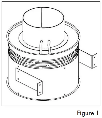
*NOTE: The CAS-34U unit can be suspended off the floor by utilizing the brackets to avoid wet or damp floors.
The Intake Air Hood should be located on an outside wall maintaining minimum clearances to other intake and exhaust vents in accordance with the National Fuel Gas Code, ANSI Z223.1, manufacturer’s recommendations and/or local codes which are applicable. The intake air hood should be located at least 10′ from a power vented exhaust outlet.
An exterior air intake should be installed above snow line or a minimum of 18″ above ground level, whichever is greater. ASHRAE recommends that the air intake be located at least 1 O feet from any source of pollutants such as auto exhaust, dryer exhaust, exhaust from any fuel-burning appliance, etc. Avoid installation near odor sources such as garbage bins or barbecue grills. Do not use a crawl space, basement or attic as a source of intake air. Always be sure to comply with local building code requirements regarding combustion air inlets.
INSTALLATION OF INTAKE AIR HOOD
After determining the location of the intake air hood, cut a 4 ½” round or square hole in the wall. Insert the intake air hood and secure with appropriate fasteners. Take precautions to avoid interference with wiring or other plumbing when cutting the wall opening.
INSTALLATION OF DUCT
Connect the duct pipe from the top of the CAS-34U unit to the Intake Air Hood in the wall. If using 4″ diameter pipe attach the provided 4″ x 6″ Pipe Increaser Fitting to the top of the CAS-34U unit. The duct should be supported with appropriate mounting straps from floor joists, walls, or other solid structures. The straps should be placed so as to keep the ductwork out of passageways. (See Figure 2) A minimum of 12′ of pipe should be run to help temper outside air being drawn in.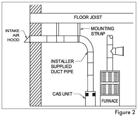
WIRING INSTRUCTIONS
Wire the CAS-34U unit in accordance with the National Electrical Code and applicable local codes. THE UNIT MUST BE GROUNDED. Check the ground circuit to make certain that the unit has been properly grounded. The wiring should be protected by an over-current circuit device rated at 15 amperes.![]() CAUTION
CAUTION
CAUTION must be taken to ensure that the wiring does not come in contact with any heat source. All line voltage and control circuits between the CAS-34U unit and the appliance MUST be wired in accordance with the National Electrical Code for Class I wiring or equivalent.
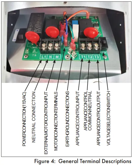
Remove the wiring access cover to access the wiring terminals. Use the enclosed conduit connector(s) to route the appropriate wires through the CAS-34U housing. The incoming ground wire must be attached to the green colored ground screw near the wire terminals. The following sections describe the most common applications. The references to various series of control kits implies that any kit in that series may be used.If further information or additional wiring diagrams are needed please consult Field Controls’ technical support.
![]() IMPORTANT
IMPORTANT
MAKE SURE TO SET THE VOLTAGE SELECTION SWITCH TO THE CORRECT POSITION FOR THE APPLICATION!
![]() WARNING
WARNING
CONNECTIONS TO MULTIPLE APPLIANCES MUST FOLLOW INSTALLATION INSTRUCTION WIRING DIAGRAMS.
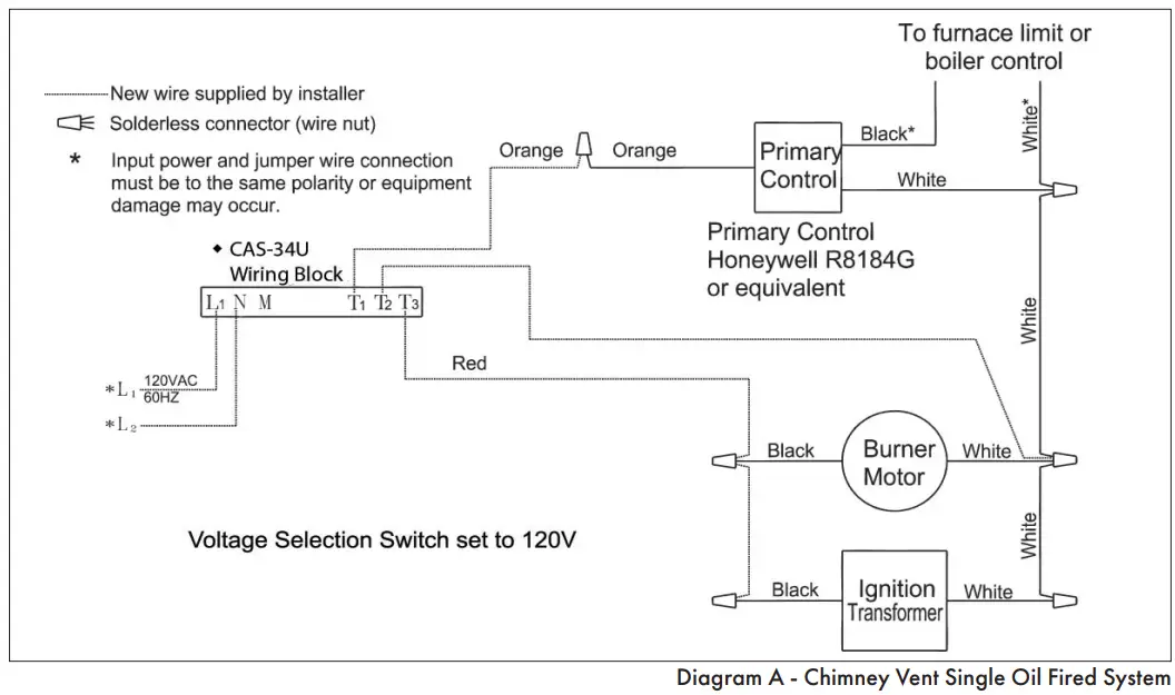
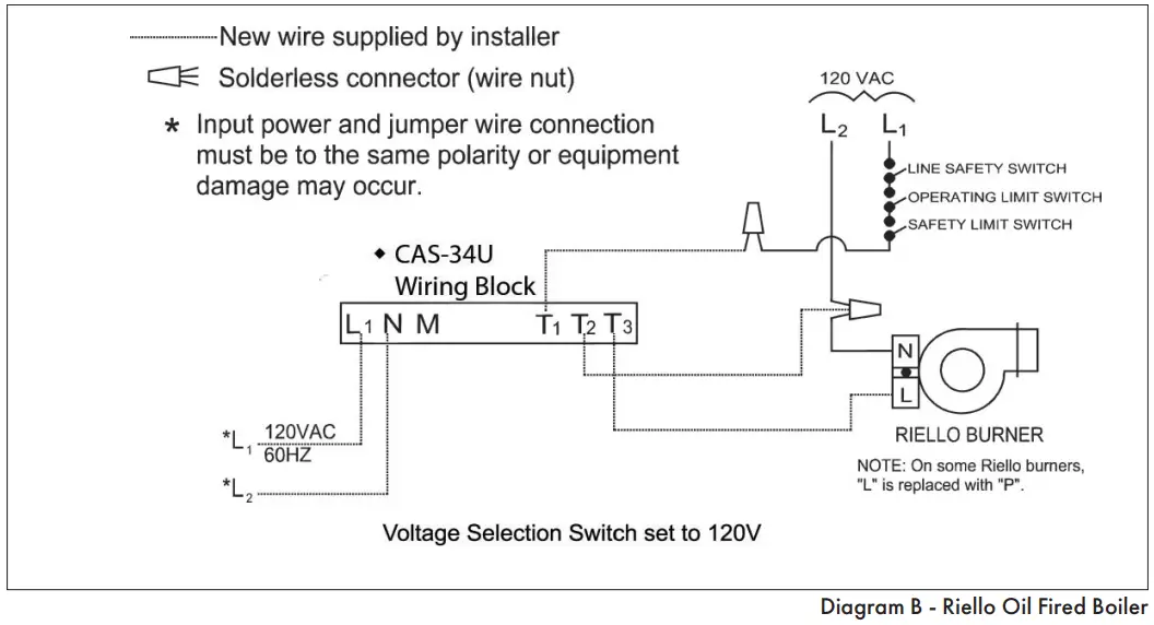
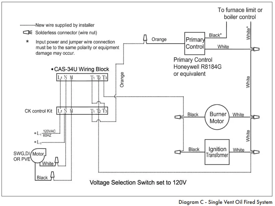
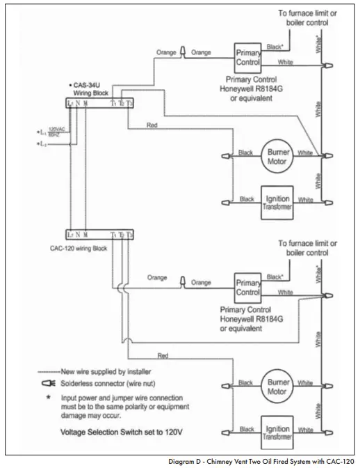
For Oil Applications, please refer to the Oil, 120VAC Section. For Gas Applications, please refer to the Gas, 24V Section.
OIL 120 VAC APPLIANCE SECTION
The “M” terminal on this appliance is no longer directly connected to the unit’s motor. The “M” terminal’s function has been changed to a 120VAC input control circuit.
EXTERNAL WIRING CONNECTIONS
Refer to Figures 3 thru 6 for appropriate wiring method.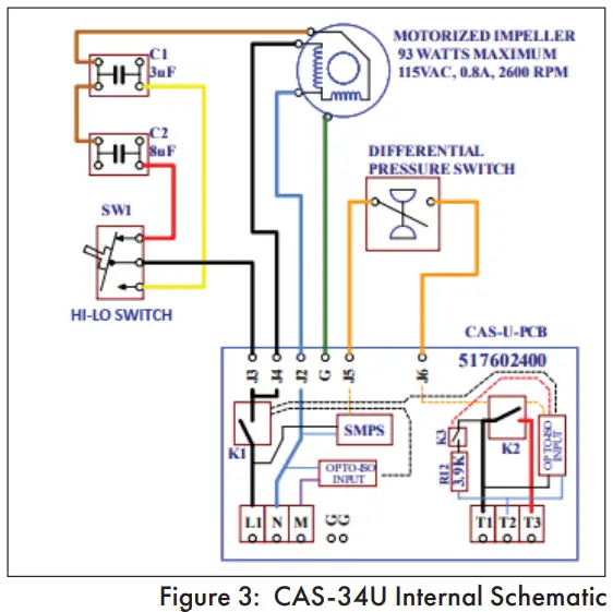
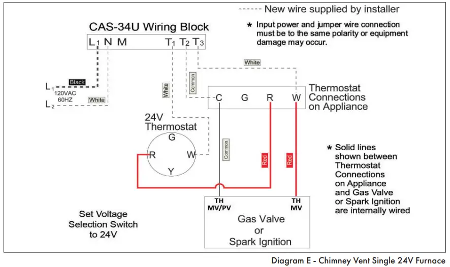
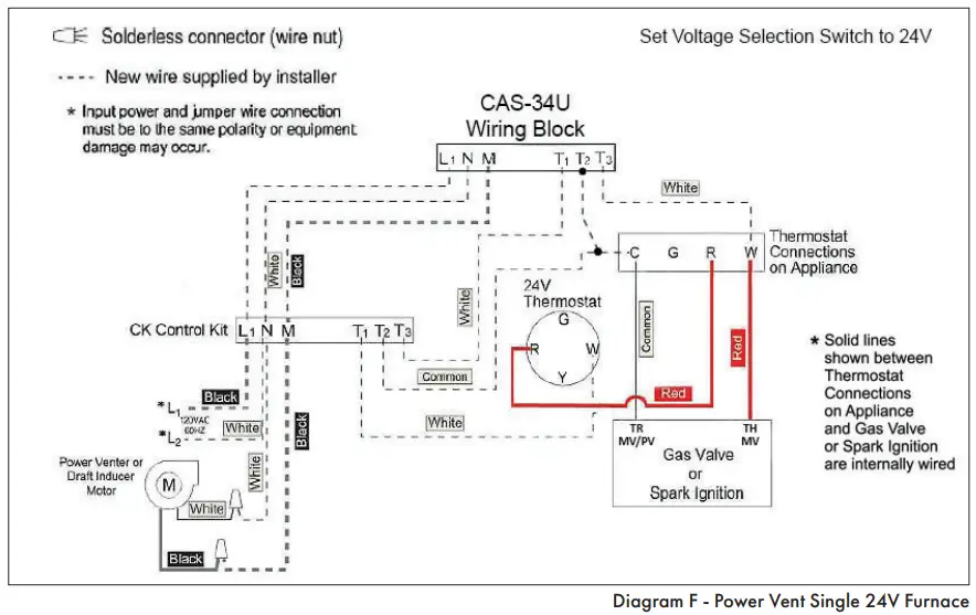
GAS 24 VAC APPLIANCE SECTION
EXTERNAL WIRING CONNECTIONS
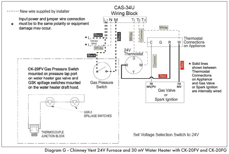
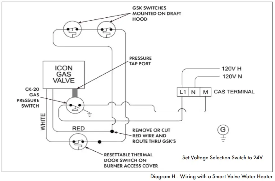
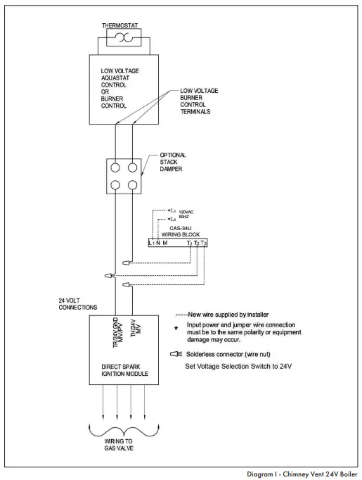
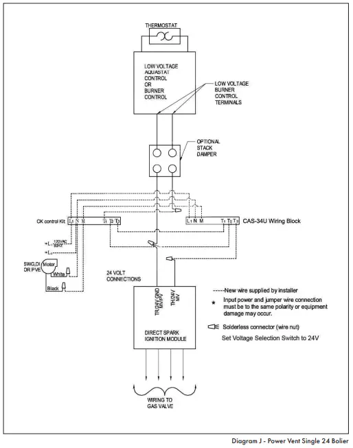
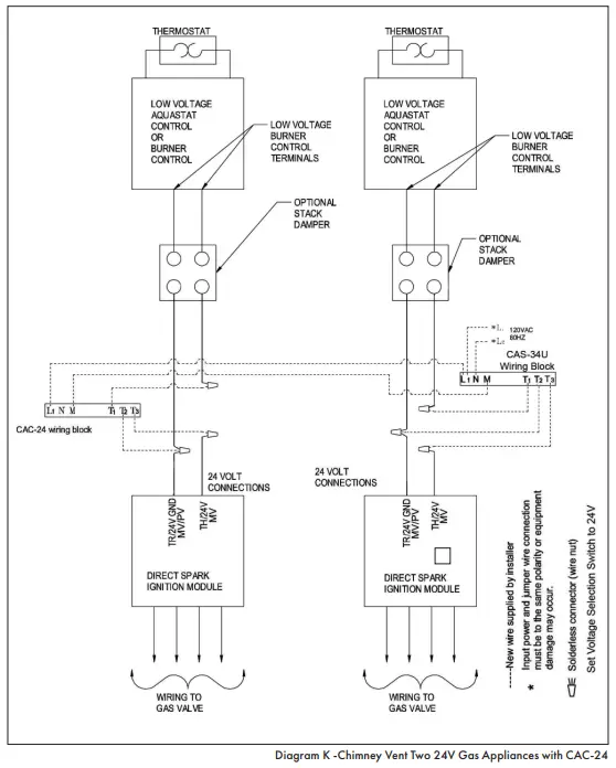
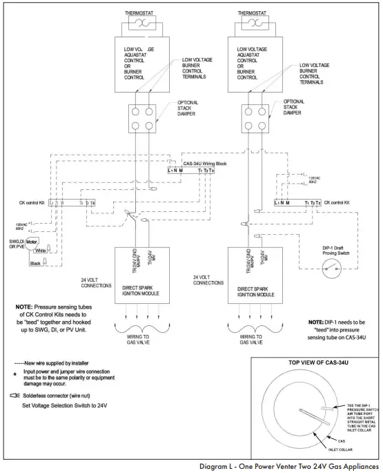
Refer to Figures 7 thru 13 for appropriate wiring method.
MAINTENANCE
- Inspect the system annually to ensure proper operation by observing that the fan activates when a call for heat occurs and deactivates when the call for heat is satisfied.
- Disconnect power to the CAS-34U unit and repeat Step 1. Note: The unit should not run and the appliance should not fire in this condition.
- Inspect the duct pipe for cracks and that it is secure to the CAS-34U unit and intake airhood. The CAS- 34U unit will not allow the appliance(s) to fire if there is inadequate air flow into the inlet of the CAS-34U.
- Clear any obstructions, if present, from the inlet of the intake air hood and the outlet of the CAS-34U unit.
- Periodically, the fan blade chamber may need cleaning. First, disconnect the power supply to the CAS-34U.
Next, disconnect the duct pipe from the unit. Then remove the top pan and clean the fan housing area as needed. Reattach the top pan, reconnect the duct pipe and the power supply.
TROUBLESHOOTING
- Burner does not fire when thermostat calls for heat.
a. Make sure draft tube is securely fastened to the air pressure switch and is not blocked.
b. Check for continuity across pressure switch terminals when system is operating.
c. Check wiring connections between air pressure switch and appliance. - System does not activate when thermostat calls for heat.
a. Check to see if relay closes when thermostat calls for heat.
b. Check wiring connections.
c. Check motor for unrestricted shaft rotation. - Exhaust gas odor.
a. Check system draft level during operation.
b. Check vent system on appliance.
c. Check for negative pressure in building.
REPLACEMENT PARTS
REPLACEMENT PARTS | ||
MODEL | DESCRIPTION | PART NO. |
| CAS-34U | PCB Control Assy, CAS-34U | 602400200 |
| Motor Assy, CAS-34U | 602400300 | |
IAH-4 Intake Air Hood | 46292000 | |
| IAH-6 Intake Air Hood | 46293000 | |
Pressure Switch, CAS-34U | 602400400 | |
This manual may be downloaded and printed from the Field Controls website (www.fieldcontrols.com)
WARRANTY
For warranty information about this or any Field Controls product, visit: www.fieldcontrols.com
CUSTOMER SUPPORT
Field Controls Technical Support
1.800.742.8368
[email protected]
Phone: 252.522.3031
• Fax: 252.522.0214
www.fieldcontrols.com