iBASE FWA6504 1U 19 Inch Network Appliance
Foreword
Copyright© 2014 IBASE Technology INC. All Rights Reserved.
No part of this manual, including the products and software described in it, may be reproduced, transmitted, transcribed, stored in a retrieval system, or translated into any language in any form or by any means, except documentation kept by the purchaser for backup purposes, without the express written permission of IBASE Technology INC. (“IBASE”).
Products and corporate names mentioned in this manual may or may not be registered trademarks or copyrights of their respective companies, and are used for identification purposes only. All trademarks are the property of their respective owners.
Every effort has been made to ensure that the contents of this manual are correct and up to date. However, the manufacturer makes no guarantee regarding the accuracy of its contents, and reserves the right to make changes without prior notice.
Safety Information
FWA6504 is designed and tested to meet the latest standards of safety for information technology equipment. However, to ensure your safety, it is important that you read the following safety instructions.
Setting up your system
- Read and follow all instructions in the documentation before you operate your system.
- Do not use this product near water.
- Set up the system on a stable surface or secure on wall with the provided rail. Do not secure the system on any unstable plane or without the rail.
- Do not place this product on an unstable cart, stand, or table. The product may fall, causing serious damage to the product.
- Slots and openings on the chassis are for ventilation. Do not block or cover these openings. Make sure you leave plenty of space around the system for ventilation. Never insert objects of any kind into the ventilation openings.
- This system should be operated from the type of power indicated on the marking label. If you are not sure of the type of power available, consult your dealer or local power company.
- Use this product in environments with ambient temperatures between 0˚C and 45˚C.
- If you use an extension cord, make sure that the total ampere rating of the devices plugged into the extension cord does not exceed its ampere rating.
Care during use
- Do not walk on the power cable or allow anything to rest on it.
- Do not spill water or any other liquids on your system.
- When the system is turned off, a small amount of electrical current still flows.
- Always unplug all power, and network cables from the power outlets before cleaning the system.
- If you encounter the following technical problems with the product, unplug the power cord and contact a qualified service technician or your retailer.
- The power cable or plug is damaged.
- Liquid has been spilled into the system.
- The system does not function properly even if you follow the operating instructions.
- The system was dropped or the cabinet is damaged.
Lithium-Ion Battery Warning
CAUTION: Danger of explosion if battery is incorrectly replaced. Replace only with the same or equivalent type recommended by the manufacturer. Dispose of used batteries according to the manufacturer’s instructions.
NO DISASSEMBLY
The warranty does not apply to the products that have been disassembled by users
FCC
Federal Communications Commission Statement
This device complies with Part 15 of the FCC Rules. Operation is subject to the following two conditions:
- This device may not cause harmful interference, and
- This device must accept any interference received including interference that may cause undesired operation.
This equipment has been tested and found to comply with the limits for a Class A digital device, pursuant to Part 15 of the FCC Rules. These limits are designed to provide reasonable protection against harmful interference in a residential installation. This equipment generates, uses and can radiate radio frequency energy and, if not installed and used in accordance with manufacturer’s instructions, may cause harmful interference to radio communications. However, there is no guarantee that interference will not occur in a particular installation. If this equipment does cause harmful interference to radio or television reception, which can be determined by turning the equipment off and on, the user is encouraged to try to correct the interference by one or more of the following measures:
- Reorient or relocate the receiving antenna.
- Increase the separation between the equipment and receiver.
- Connect the equipment to an outlet on a circuit different from that to which the receiver is connected.
- Consult the dealer or an experienced radio/TV technician for help.
CAUTION: Any changes or modifications not expressly approved by the grantee of this device could void the user’s authority to operate the equipment.
CE Mark Warning
This is a Class A product, in a domestic environment, this product may cause radio interference, in which case the user may be required to take adequate measures.
Introduction
The FWA6504 was specifically designed for the network security & management market.
Network Security Applications:
- Firewall
- Virtual Private Network
- Proxy Server
- Caching Server
Network Management Applications:
- Load balancing
- Quality of Service
- Remote Access Service
The FWA network appliance product line covers the spectrum from offering platforms designed for :
- SOHO
- SMB
- Enterprise
Each product is designed to address the distinctive requirements of its respective market segment from cost effective entry-level solutions to high throughput and performance-bound systems for the Enterprise level.
System Specification
Product Description
FWA6504 incorporates Intel® NM10 chipset. Currently, it is available in the following model:
| Model | Intel® Atom Dual Core CPU | Watchdog Timer | |
| FWA6504 | Atom D2550 | 1.86 GHz | Yes |
FWA6504 Features
- Supports four intel® 10/100/1000 LAN ports
- DDR3 SO-DIMM x 1, up to 4GB
- Mini PCI-e (USB Signal) slot, Mini PCI slot & Compact Flash socket
- LAN bypass Enable / Disable pre-setting by BIOS when power on / off
FWA6504 Specifications
| Form Factor | 1U 19” rackmount |
| CPU Type Operating Frequency | Intel “Cedar view” Processor, 32nm Bulk Atom D2550 = 1.86 GHz [TDP= 10W], Cores = Dual Core |
| Chipset | Intel “Tiger Point” PCH, CG82NM10 [TDP = 2.1W, 130 nm] |
| BIOS | AMI BIOS w/ACPI |
| Ethernet controller | Intel 82583V PCI Express Gigabit ethernet controller x4 |
| Memory | CPU on-die memory controller supporting up to 4GB One DDR3-1066 SO-DIMM socket, Non-ECC, unbuffered, 1.5V |
| LAN | l Console: RS-232 @ RJ45 l Eth1, 2, 3 & 4: Intel 82583V @ RJ45 with LED |
| Network Bypass | One segment hardware Bypass (Eth1 & 2, Optional) Control by GPIO / Watchdog / Electrical Disconnect (Power Off) |
| Watchdog Timer | Yes (256 segments, 0, 1, 2…255 sec/min) |
| Storage | l Onboard CF Socket x1 l 22-pin SATA Right Angle Connector Onboard for 2.5” SSD x1 |
| Front Panel | l Factory Mode Restore Reset Switch (GPIO control) l RJ45 x1 for Console l RJ45 with LED x4 for Gigabit LAN Ports l USB 2.0 x2 l LED: Power (Green) / Alarm (Red) / Status (Yellow) |
| Rear Panel | l AC Inlet |
| Video | Optional VGA Port on Front Panel |
| Internal I/O Headers | l 4-pin Smart Fan Connector x1 l 2-pin header for DC-in (12V) x1 l Keyboard + Mouse ([1×6] Pin Header) x1 |
| Expansion Interface | l Mini PCI Socket, Mini PCI-e Socket x1 (USB Signal Only) |
| Power Supply | Full range 40W supply / 12V |
| Dimensions | 430(W) x 216(D) x 44(H) mm |
| Operation Temperature | 0 ~ 45 ˚C (32 ~ 113 ˚F) |
| Storage Temperature | -20 ~ 70 ˚C (-4 ~ 158 ˚F) |
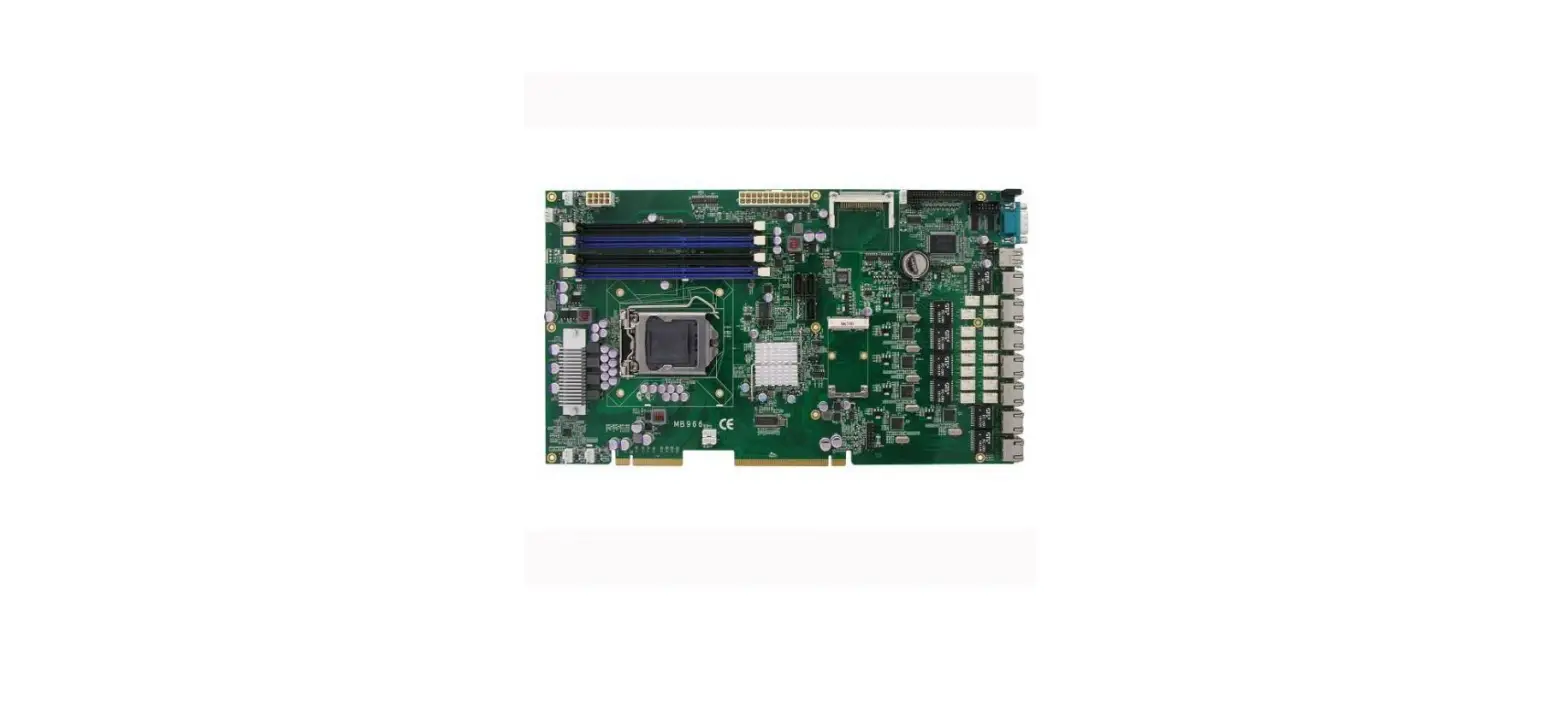
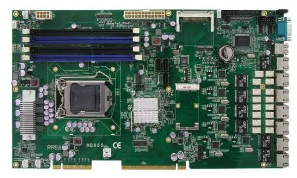
Hardware Configuration
Motherboard (MB837-1U) Layout 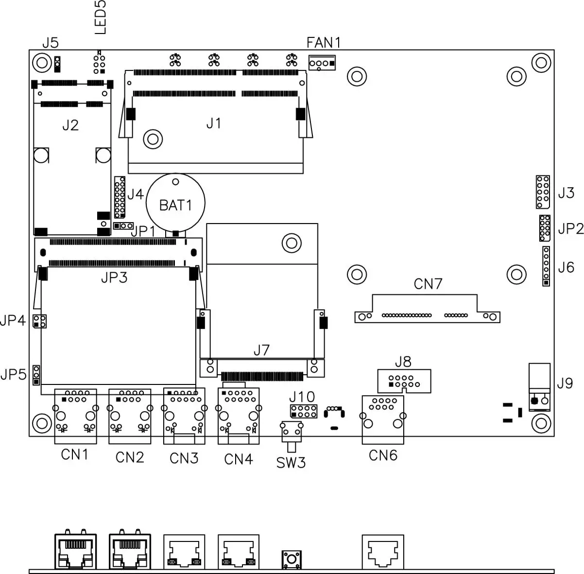
The Jumpers
JP1: Clear CMOS Contents
Use JP1 to clear the CMOS contents.
Note that the power connector or jack should be disconnected from the board before clearing CMOS.
| JP1 | Setting | Function |
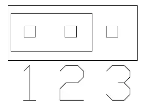 | Pin 1-2 Short/Closed | Normal |
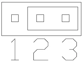 | Pin 2-3 Short/Closed | Clear CMOS |
JP4, JP5: LAN Bypass & WDT Reboot Setting
| JP4 JP5 | Setting | Function | Power OFF | Power ON | Power ON OS run software | |||
| Normal | Bypass | Normal | Bypass | Normal | Bypass | |||
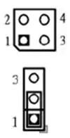 | JP4 1-2 & 3-4 Open JP5 1-2 Closed | LAN bypass upon the time out of WDT. | P | P | P | |||
 | JP4 3-4 Closed 1-2 Open JP5 1-2 Closed | LAN bypass & system reboot upon the time out of WDT. | P | P | LAN Always Normal | |||
| WDT Reboot System | ||||||||
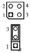 | JP4 1-2 & 3-4 Open JP5 2-3 Closed | LAN bypass controlled by Super IO GP54 or setting in BIOS. | BIOS Setting ** GP54 Active: Low: Bypass High: Normal | |||||
** Note that the Bypass setting in BIOS is only working when JP4 & JP5 are set as this configuration.
The Connectors
FAN1: System Fan Power Connector
FAN1 is 4-pin header for System fan power. The fan must be a 12V fan.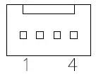
| Pin # | Signal Name |
| 1 | Ground |
| 2 | +12V |
| 3 | Rotation detection |
| 4 | Control |
CN1, CN2, CN3, CN4: 10 / 100 / 1000 LAN Ports
CN6: COM1 RJ45 Connector
| Pin # | Signal Name (RS-232) |
| 1 | RTS, Request to send |
| 2 | DTR, Data terminal ready |
| 3 | TXD, Transmit data |
| 4 | Ground |
| 5 | Ground |
| 6 | RXD, Receive data |
| 7 | DSR, Data set ready |
| 8 | CTS, Clear to send |
CN7: SATA SSD Dock
The SATA SSD dock combines a SATA power connector and a SATA interface connector.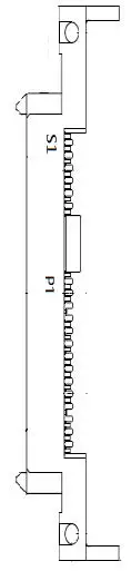
| Signal Name | Pin # | Pin # | Signal Name |
| GND | S1 | P1 | +3.3V |
| A+ | S2 | P2 | +3.3V |
| A- | S3 | P3 | +3.3V |
| GND | S4 | P4 | GND |
| B+ | S5 | P5 | GND |
| B- | S6 | P6 | GND |
| GND | S7 | P7 | +5V |
| P8 | +5V | ||
| P9 | +5V | ||
| P10 | GND | ||
| P11 | GND | ||
| P12 | GND | ||
| P13 | +12V | ||
| P14 | +12V | ||
| P15 | +12V |
J1: SO-DIMM DDR3 Socket
J2: Mini PCI-e Connector (USB signal only)
J3: SPI Debug Port (Factory use only)
J4: VGA Header
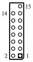
| Signal Name | Pin # | Pin # | Signal Name |
| DACR | 1 | 2 | +5VCRT | |
| DACG | 3 | 4 | GND | |
| DACB | 5 | 6 | NC | |
| NC | 7 | 8 | CRT_SPD | |
| GND | 9 | 10 | HSYNC_C | |
| +5VCRT | 11 | 12 | VSYNC_C | |
| GND | 13 | 14 | CRT_SPCLK | |
| GND | 15 |
J6: PS2 Keyboard / Mouse Header
| Pin # | Signal Name |
| 1 | KBDATA |
| 2 | KBCLK |
| 3 | MSDATA |
| 4 | MSCLK |
| 5 | GND |
| 6 | +5V |
J7: Slim Type II Compact Flash Connector
J8: COM2 Serial Port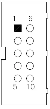
| Pin # | Signal Name (RS-232) |
| 1 | DCD, Data carrier detect |
| 2 | RXD, Receive data |
| 3 | TXD, Transmit data |
| 4 | DTR, Data terminal ready |
| 5 | Ground |
| 6 | DSR, Data set ready |
| 7 | RTS, Request to send |
| 8 | CTS, Clear to send |
| 9 | RI, Ring indicator |
| 10 | No Connect. |
J9: AT_12V Connector
J9 is a DC-in internal connector supporting +12V.
 | Pin # | Signal Name |
| 1 | +12V | |
| 2 | Ground |
Note: Do not connect J9 and J11 at the same time.
J10: USB Header
| Signal Name | Pin # | Pin # | Signal Name |
| VCC | 1 | 2 | Ground |
| USB1- | 3 | 4 | USB2+ |
| USB1+ | 5 | 6 | USB2- |
| Ground | 7 | 8 | VCC |
LED5: Power, Alarm & Status LED Pin Header
| Signal Name | Pin # | Pin # | Signal Name |
| PWR LED+ | A1 | C1 | PWR LED- |
| ALARM LED+ | A2 | C2 | SIO GPIO55 |
| STATUS LED+ | A3 | C3 | SIO GPIO56 |
SW3: Software Reset Button
| Signal Name | Pin # | Pin # | Signal Name |
| GND | 1 | 2 | PCH GPIO7 |
Note: SW3 is controlled by GPIO only.
JP3: Mini-PCI Connector
Console Mode Information
FWA6504 supports output information via Console in BIOS level.
Prepare a computer as client loaded with an existing OS such Windows XP.
Connect client computer and FWA6504 with NULL Modem cable.
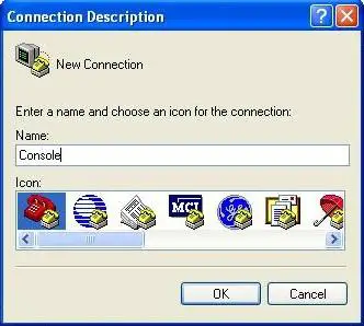
Follow the steps below to configure the Windows Hyper Terminal application setting:
- For executing the Hyper Terminal, issue command “hypertrm”.
- Customize your name for the new connection.

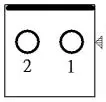
- Choose the COM port on the client computer for the connection.

- Please make the port settings to Baud rate 115200, Parity None, Data bits 8, Stop bits 1

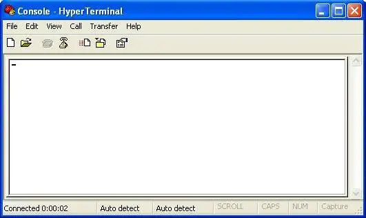
- Power up FWA6504 and the screen will display the BIOS information.
- Press <Tab> key to enter BIOS setup screen in Console mode. Press <Del> key to enter BIOS setup screen in VGA mode.

Opening the Chassis
Loosen6 screws on back, left and right sides
The system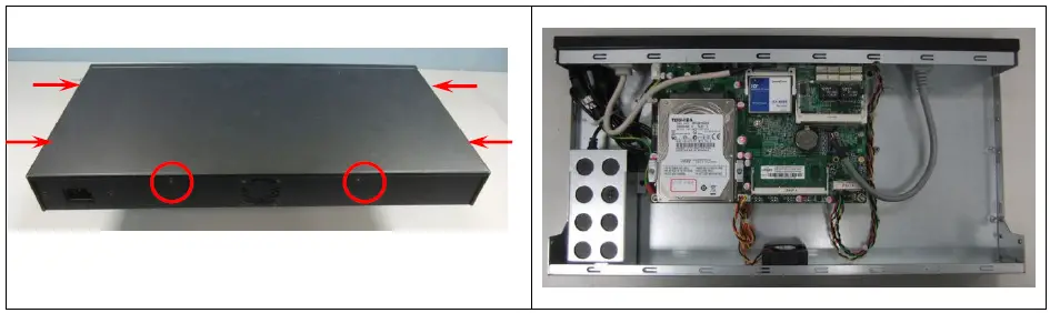
Installing CompactFlash Card
Fig. 6-1 Insert Compact Flash Card
Fig. 6-2 Push Compact Flash Card into the CF interface 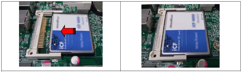
Installing Memory Module
Fig. 7-1 Insert DDR3 SO-DIMM memory module
Fig. 7-2 Press down the memory module into socket 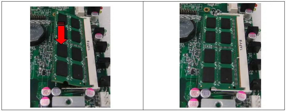
Installing 2.5” SSD
Fig. 8-1 Loosen two screws to remove left & right side brackets
Fig. 8-2 Fasten brackets on SSD with four screws 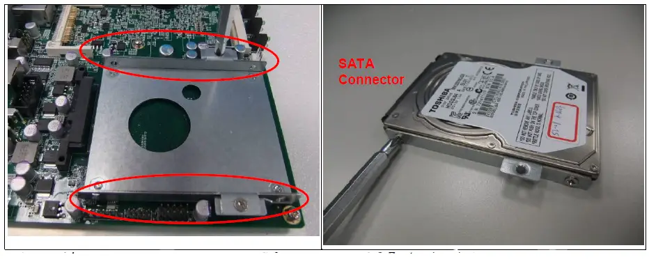 Fig. 8-3 Fasten both brackets on SSD with four screws
Fig. 8-4 Fix SSD & brackets with two screws 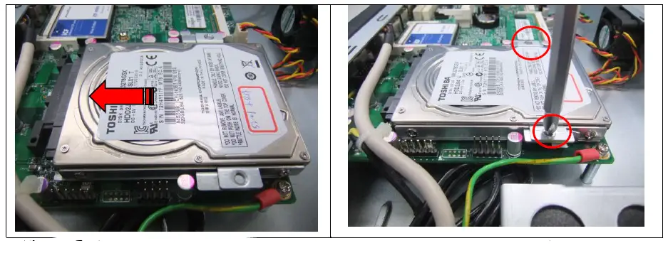
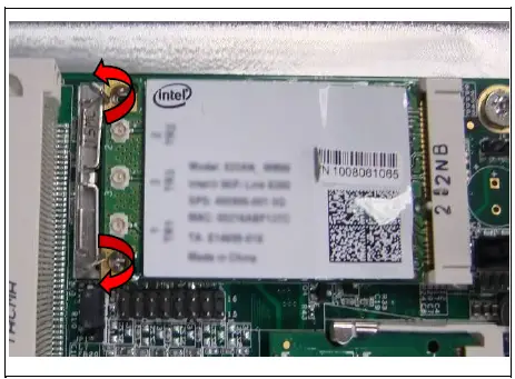
Installing Mini PCI-e Module
Fig. 9-1 Insert Mini PCI-e module (Supports USB signal only)
Fig. 9-2 Push down the module into socket 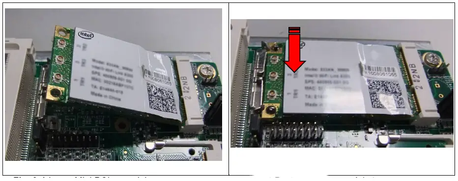 Fig. 9-3 Release two clips to remove module