bsi Mid Height Bridging Wall Unit
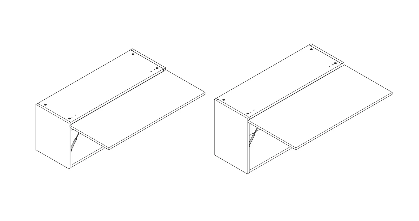
600 and 900 Mid Height Bridging Wall Unit Assembly
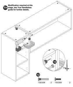
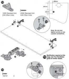
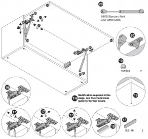
Note: If fitting a “True Handle less” kitchen, some components will differ to those shown in this instruction and will also be packaged separately.
Please refer to your True Handle less guide to Receiving for further details on the different components and difference in installation.
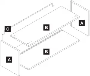
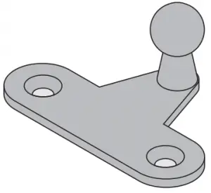
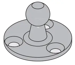
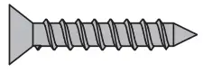
Components
Important Information
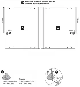
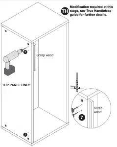
True Handleless Kitchens Installers
See Note Above
Caution: Some pieces of hardware could be hazardous to small children. Keep all these items out of reach and do not leave children unattended in the assembly area.
Please read these instructions carefully before proceeding. Refer to the Guide to Receiving and Installing your Kitchen booklet for further information.
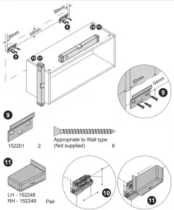
Note: Due to variation in wall conditions no screws are supplied for fixing the units to the wall. If in doubt consult an expert. Assemble the unit on a clean solid work surface.
In the interest of continuing improvements we reserve the right to amend or adjust the specifications without prior notice. Errors and omissions excepted. Every effort has been made to ensure that this product leaves the factory in perfect condition. In the unlikely event that an item is damaged or incorrect, please contact the customer services department.
Note – Fitting Handles: (1) Decide where you are going to position each handle to maintain symmetry around your kitchen. (2) Measure the handle centers and mark off each door/drawer position. (3) Drill through the door/drawer using a fine drill (<2.5mm), then drill back from the rear face using a 4.5mm drill. (4) Attach with the fixings provided with your handle.
| Ref. No. | Item | Quantity |
| 150101 |  | 4 |
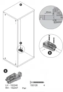
| 150126 |  | 4 |
| 154082 |  | 8 |
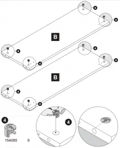
| 154085 |  | 8 |
| 154004 |  | 8 |
| 150308 |  | 2 |
| 150309 |  | 2 |
| 152148 |  | 2 |
| 151101 |  | 4 |
| 151999 |  | 2 |
| 152181 |  | 2 |
| 152162 |  | 2 |
| LH – 152246 RH – 152247 |  | Pair |
| LH – 152248 RH – 152249 |  | Pair |
| 152201 |  | 2 |
| 154016 | Stay arm kit each containing: | 1/2 |
| 1 | ||
 | 1 | |
 | 1 | |
 | 1 | |
 | 5 |
Tools Required
| Drill | 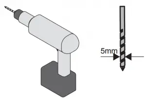 |
| Medium Crosshead Screwdriver |  |
| Large Flathead Screwdriver |  |
| Spirit Level |  |
| G-Clamp (pair) |  |
| Hammer |  |
| Tape Measure |  |
| Bradawl |  |
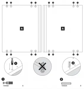
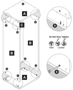
Assembly Instructions
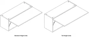
Note: Instruction shows assembly for standard height unit. Construction is same for tall height units.
Installation Instructions