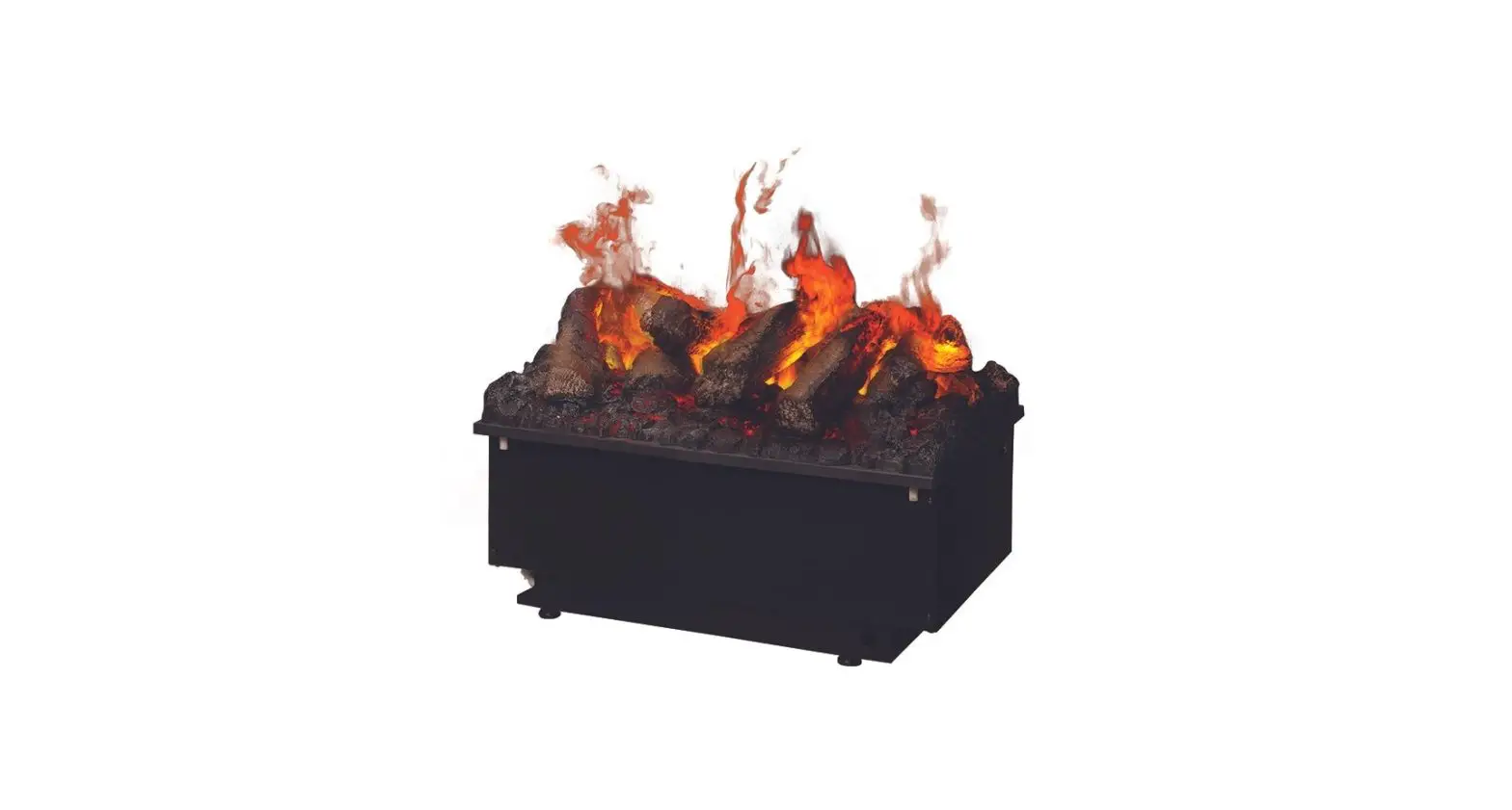
Dimplex CDFI500P Opti-Myst Pro Clectric Cassette Owner’s Manual
IMPORTANT SAFETY INFORMATION: Always read this manual first before attempting to service this cassette. For your safety, always comply with all warnings and safety instructions contained in this manual to prevent personal injury or property damage.
Always use a qualified technician or service agency to repair this cassette.
NOTE: Procedures and techniques that are considered important enough to emphasize.
CAUTION: Procedures and techniques which, if not carefully followed, will result in damage to the equipment.
WARNING: Procedures and techniques which, if not carefully followed, will expose the user to the risk of fire, serious injury, or death.
Operation
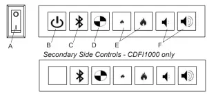
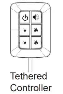
Figure 1: Primary Side Controls
![]() WARNING: This unit must be properly installed before it is used. Air intakes located below the unit are essential. See “Installation” section of the Owner’s Manual for further information.
WARNING: This unit must be properly installed before it is used. Air intakes located below the unit are essential. See “Installation” section of the Owner’s Manual for further information.
There are three different control options available for the unit: manual (under the media plate), tethered controller (must be connected to the unit) and a remote control.
The CDFI1000P and the CDFI1000-PRO units have two separate internal modules that are controlled by the settings entered on the left side (primary). The primary side controls include the power switch and standby button, whereas the secondary side controls do not. Finer adjustment can be done using the controls on the right module to have both modules operating at the same level (secondary).
NOTE: When the unit is used in an environment where background noise is very low, it may be possible to hear a sound which is related to the operation of the flame effect. This is normal and should not be a cause for concern.
NOTE: Always ensure that the appliance is fixed to the framing in a level position.
Controls
A. On/Off Switch
Supplies power to the unit.
When the switch is set to the On position, the unit will emit one beep. The unit will be in standby mode when it is first powered on. The unit can be operated using any of the control options (onboard, tethered controller, or remote control).
NOTE: When the unit is first turned on the lights will come on and mist will appear 45 seconds later.
B. ![]() Standby
Standby
Turns the operation of the flame effect on or off.
C. ![]() Bluetooth
Bluetooth
Required for synchronization of the remote, see synchronization instructions for more detail.
D. ![]() Test Mode
Test Mode
Used for troubleshooting issues – outlined in the Test Mode section of this service manual
E. Flame Intensity Control
Adjusts the intensity of the flame and smoke effect when the unit has been activated.
Pressing the ![]() will decrease the flame effect and pressing the
will decrease the flame effect and pressing the![]() will increase the flame effect. One beep will be heard when the flame height has reached the minimum or maximum level.
will increase the flame effect. One beep will be heard when the flame height has reached the minimum or maximum level.
NOTE: A few moments will be required between adjustment and a change to the flame effect.
NOTE: During normal operation it is expected to see some condensation of water on the media plate. This will vary depending on ambient conditions and should be considered normal.
NOTE: When the water tank is empty, the flame effect shuts OFF and the LED’s will blink.
F. Volume Control
Adjusts the volume of the wood fire sound effects.
On the unit: Pressing the will ![]() decrease the volume and pressing
decrease the volume and pressing ![]() the will increase the volume.
the will increase the volume.
On the Remote and Tethered Controller: Pressing the ![]() will turn the volume On and Off.
will turn the volume On and Off.
Remote Control
Figure 2
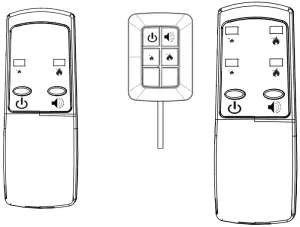
Remote Control and Tethered Controller for CDFI500P
NOTE: The icons with 1 dot indicate controls for the primary and 2 dots indicate controls for the secondary.
Remote Control and Tethered Controller for CDFI1000P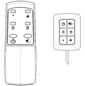
Remote Control and Tethered Controller for CDFI500-PRO and CDFI1000-PRO
The tethered controller serves as the bluetooth receiver for communication with the remote, and must be connected for remote operation of the unit. It can also be used in the same manner as the remote.
The tethered controller must be connected to the unit and On/ Off Switch must be in the ‘ON’ ( I ) position in order for the remote to operate.
NOTE: To operate correctly the remote control must be synchronized with the unit.
Remote Control Synchronization / Pairing
In order for the remote control to communicate with the unit the bluetooth must be setup, as outlined below:
- Verify that the tethered controller is connected correctly and that the plug is inserted all the way.
- Place the On/Off Switch (Figure 1A) in the ON (“I”) position. The red light on the tethered controller will be illuminated.
- Press the Standby button to activate the flame effect.
- Press the Bluetooth synchronization button on the Primary controls (left side).
- The unit will begin to beep and turn the lights ON and OFF every 2 ½ seconds to indicate that the unit is in synchronization mode.
- Within 20 seconds of pressing the blue tooth button, press any button on the remote control (Figure 1).
NOTE: You will have only 20 seconds to perform this last step. Failure to do so will result in these steps needing to be followed again. - If the synchronization was successful the LED’s will blink 5 times and beep 5 times then the unit will go to Standby
This will synchronize the remote control and the tethered controller.
NOTE: It is possible to synchronize up to 5 units to one remote control.
Battery Replacement
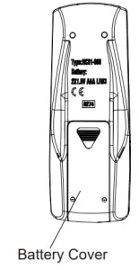
Figure 3
To replace the battery:
- Slide battery cover open on the remote control (Figure 3).
- Install two 1.5 Volt (AAA) battery in the battery holder.
- Close the battery cover.
 Battery must be recycled or disposed of properly. Check with your Local Authority or Retailer for recycling advice in your area
Maintenance
WARNING: Disconnect power before attempting any maintenance or cleaning to reduce the risk of fire, electric shock or damage to persons.
Filling the water tank (Refillable bottle)
When the water tank is low, the flame effect will shut off and the unit will emit an audible beep and continuously blink twice every ten seconds. To refill the bottle(s), follow these steps.
- Gently remove the top tray and place it carefully on the ground.
- Turn the On/Off switch to the off position (0) (Figure 1A)
- Remove the refill container by lifting upwards and outwards.
- Refill the container with tap water.
NOTE: Normal tap water can be used in the Optimyst® as long as the tap water is not considered to be hard water. In the event your tap water is hard, you may use softened water or distilled water with ⅛ tsp. of salt (0.5 mL) added to the water reservoir. (The use of additional salt should only be when you notice that the unit is not producing mist as expected.) - Screw the cap back on, do not overtighten.
- Return the refill container to the sump, with the tank cap facing down and the flat side of the tank facing outward.
- Turn the On/Off switch to the off position (I). (Figure 1A)
- Gently place the top tray back into position.
If you do not intend on using the unit for longer than 2 weeks, empty and drain the unit of water, and dry all of the water containing components.
Transducer Replacement
After prolonged usage the ability for the unit to produce mist may become reduced. When this occurs the replacement of the transducer may be required. This unit comes with 2 additional transducers, located behind the right module, which can installed when this occurs.
NOTE: There is a small tab that holds the transducer in place, that needs to be released before it can be removed.
Cleaning
It is recommended that the top cover assembly, sump and transducer are cleaned with soap and water on a biweekly basis.
CAUTION: Do not put plastic components in the dishwasher.
Filter Cleaning
The air filters can be removed and gently rinsed with water to clean and dried on a towel before reinstalling.
NOTE: Replace the filter so that the course black filter is facing the back of the unit.
Surface Cleaning
Use a warm damp cloth only to clean surfaces of the unit. Do not use abrasive cleaners.
NOTE: If you need to move the unit ensure that all of the components that contain water have been emptied before relocating.
Servicing
Except for installation and cleaning described in this manual, an authorized service representative should perform any other servicing.
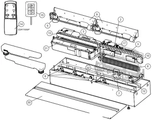
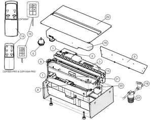
Exploded Parts Diagram – CDFI1000
Replacement Parts List – CDFI1000P, CDFI10000-PRO
- Main Control Board (2): 9601270200RP
- PRO MOD C*: 9601270300RP
- Terminal Block (1): 9601260100RP
- Switch Board (2): 9601290100RP
- Power Supply (2): 9601300100RP
- Fill Cap Assembly (2): 9601230100RP
- Heating Element (2): 9601240100RP
- Level Sensor Assembly (2): 9601320100RP
- Solenoid Valve (2): 9601330100RP
- Top Cover Assembly (2): 9601220100RP
- Fan Assembly (2): 9601310100RP
- Fan Filter (2): 8600300100RP
- Transducer (2): 9601210100RP
- LED Light Assembly (2): 9601250100RP
- PRO MOD C (Yellow)* (2): 9601250200RP
- LED Driver Board: 9601270300RP
- Remote Control
- CDFI1000P: 9601110100RP
- CDFI1000-PRO: 9601110300RP
- Tethered Controller / Receiver
- CDFI1000P: 9601120100RP
- CDFI1000-PRO: 9601120300RP
- Fused Wire Harness: 9601340100RP
- Electronic Choke (2): 9601380100RP
- Removable Refill Container with Cap: 9601350100RP
- Ball Valve (1): 9601360100RP
- Top Plate
- CDFI1000P: 9601070100RP
- CDFI1000-PRO: 9601070300RP
- Sump (2): 9601200100RP
- Floats and stopper (2): 9602550100RP
- Mesh filter (1): 9601370100RP
- Red lock clips (package of 5): 9602490100RP
- Tether Wire Harness: 9601080100RP
- Flame Spacers (2): 9601460100RP
Note that if yellow LEDs are used as replacements for earlier MODs with original Main Board, new LED Driver Board (9601270300RP) will need to be installed (included with newer main control boards). All LEDs will need to be changed for colour consistency.
Exploded Parts Diagram – CDFI500
Replacement Parts List – CDFI500P, CDFI500-PRO
- Main Control Board: 270200RP
- Terminal Block: 9601260100RP
- Switch Board: 9601290100RP
- Power Supply: 9601300100RP
- Fill Cap Assembly: 9601230100RP
- Heating Element: 9601240100RP
- Level Sensor Assembly: 9601320100RP
- Solenoid Valve: 9601330100RP
- Top Cover Assembly: 9601220100RP
- Fan Assembly: 9601310100RP
- Fan Filter: 8600300100RP
- Transducer: 9601210100RP
- LED Light Assembly: 9601250100RP
- PRO MOD C (Yellow): 9601250200RP
- LED Driver Board: 9601270300RP
- Remote Control (1)
- CDFI500P: 9601110200RP
- CDFI500-PRO: 9601110300RP
- Tethered Controller / Receiver (1)
- CDFI500P: 9601120200RP
- CDFI500-PRO: 9601120300RP
- Fused Wire harness: 9601340100RP
- Electronic Choke: 9601380100RP
- Removable Refill Container with Cap: 9601350100RP
- Ball Valve: 9601360100RP
- Top Plate
- CDFI500P: 9601070200RP
- CDFI500-PRO: 9601070400RP
- Sump: 9601200100RP
- Floats and stopper: 9602550100RP
- Mesh Filter: 9601370100RP
- Red lock clips (package of 5): 9602490100RP
- Tether Wire Harness.: 9601080100RP
- Flame Spacers: 9601460100RP
Note that if yellow LEDs are used as replacements for earlier MODs with original Main Board, new LED Driver Board (9601270300RP) will need to be installed (included with newer main control boards). All LEDs will need to be changed for colour consistency.
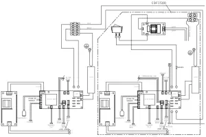
Wiring Diagram
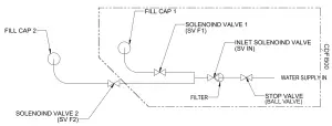
Water Flow Diagram
Switch Board Replacement
Tools Required: Phillips head screwdriver
WARNING: Disconnect power before attempting any maintenance to reduce the risk of electric shock or damage to persons.
NOTE: Ensure that all of the components that contain water have been emptied and source water has been turned off before performing any maintenance.
- Disconnect and remove the media tray or log set from the unit and put them in a safe place.
- On the side the replacement is required, remove the securing screws and metal wire cover.
- Remove the 4 screws and the electronics cover from the unit. (Figure 4)
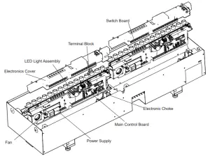
Figure 4
NOTE: Use caution when removing the electronics cover, to prevent strain on the connector wire attached to it. - Locate the switch board to be replaced.
- Gently lift the switch board off of the mounting stands.
- Disconnect the wire connection from the back of the board.
- Attach the wire connection to the new board and place on the mounting stands.
- Re-assemble the remainder of the cassette in reverse order from the instructions above.
Terminal Block Replacement
Tools Required: Phillips head screwdriver
WARNING: Disconnect power before attempting any maintenance to reduce the risk of electric shock or damage to persons.
NOTE: Ensure that all of the components that contain water have been emptied and source water has been turned off before performing any maintenance.
- Disconnect and remove the media tray or log set from the unit and put them in a safe place.
- On the secondary side remove the securing screws and metal wire cover.
- Remove the 4 screws and the electronics cover from the unit. (Figure 4)
NOTE: Use caution when removing the electronics cover, to prevent strain on the connector wire attached to it. - Locate the terminal block to be replaced.
- Disconnect the wire connections from the original block and install it on the new block.
- Replace the terminal block in the original position – the terminal block is located so that it sits on the moulded pins on the surface below.
- Re-assemble the remainder of the cassette in reverse order from the instructions above.
Fan Assembly Replacement
Tools Required: Phillips head screwdriver
WARNING: Disconnect power before attempting any maintenance to reduce the risk of electric shock or damage to persons.
NOTE: Ensure that all of the components that contain water have been emptied and source water has been turned off before performing any maintenance.
Primary Side
- the unit and put them in a safe place.
- Remove the securing screws and metal wire cover at the end of both of the electronics covers.
- Remove the 4 screws and both of the electronics covers from the unit. (Figure 4)
NOTE: Use caution when removing the electronics cover, to prevent strain on the connector wire attached to it. - Holding the assembly at either end of the LED light strip, on the primary end, gently lift the electronics assembly out of the unit (Figure 4).
NOTE: There are several wires that run between the two sides, these wires will need to be gently removed through the opening on the secondary side to allow the primary electronics assembly to be lifted out. - Locate the fan assembly.
- Trace the control wires to the main control board and disconnect.
- Replace with wire from new fan.
- Run wiring back to location for fan, and install the fan.
- Reinsert the electronics assembly.
CAUTION: Ensure that the switchboard and terminal block have not moved from their original locations and all wires are contained under the cover before reassembly. - Re-assemble the remainder of the cassette in reverse order from the instructions above.
Secondary Side
- Disconnect and remove the media tray or log set from the unit and put them in a safe place.
- Remove the 4 screws and the electronics cover from the unit. (Figure 4)
NOTE: Use caution when removing the electronics cover, to prevent strain on the connector wire attached to it. - Holding the assembly at either end of the LED light strip, on the primary end, gently lift the electronics assembly out of the unit (Figure 4).
- Locate the fan assembly.
- Trace the control wires to the main control board and disconnect.
- Replace with wire from new fan.
- Run wiring back to location for fan, and install the fan.
- Reinsert the electronics assembly.
CAUTION: Ensure that the switchboard and terminal block have not moved from their original locations and all wires are contained under the cover before reassembly. - Re-assemble the remainder of the cassette in reverse order from the instructions above.
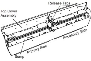
Figure 5
Fused Wire harness Replacement
Tools Required: Phillips head screwdriver
WARNING: Disconnect power before attempting any maintenance to reduce the risk of electric shock or damage to persons.
NOTE: Ensure that all of the components that contain water have been emptied and source water has been turned off before performing any maintenance.
Primary Side
- Disconnect and remove the media tray or log set from the unit and put them in a safe place.
- Remove the securing screws and metal wire cover at the end of both of the electronics covers.
- Remove the 4 screws and both of the electronics covers from the unit. (Figure 4)
NOTE: Use caution when removing the electronics cover, to prevent strain on the connector wire attached to it. - Remove the cable clamp, to allow for the assembly to be lifted out to better access the components.
- Holding the assembly at either end of the LED light strip, on the primary end, gently lift the electronics assembly out of the unit (Figure 4).
NOTE: There are several wires that run between the two sides, these wires will need to be gently removed through the opening on the secondary side to allow the primary electronics assembly to be lifted out. - Locate the fused wire harness (brown wire from main switch to main control board with in line fuse).
- Replace current wire harness with new wire harness.
NOTE: A flat head screwdriver can be used to gently pry between the end of the connector and the switch to release the wires. - Replace all of the wiring to their original locations and reinsert the electronics assembly.
CAUTION: Ensure that the switchboard and terminal block have not moved from their original locations and all wires are contained under the cover before reassembly. - Re-assemble the remainder of the cassette in reverse order from the instructions above.
Main Control Board Replacement
Tools Required: Phillips head screwdriver
WARNING: Disconnect power before attempting any maintenance to reduce the risk of electric shock or damage to persons.
NOTE: Ensure that all of the components that contain water have been emptied and source water has been turned off before performing any maintenance.
Primary Side
- Disconnect and remove the media tray or log set from the unit and put them in a safe place.
- Remove the securing screws and metal wire cover at the end of both of the electronics covers.
- Remove the 4 screws and both of the electronics covers from the unit. (Figure 4)
NOTE: Use caution when removing the electronics cover, to prevent strain on the connector wire attached to it. - Remove the cable clamp, to allow for the assembly to be lifted out to better access the components.
- Holding the assembly at either end of the LED light strip, on the primary end, gently lift the electronics assembly out of the unit (Figure 4).
NOTE: There are several wires that run between the two sides, these wires will need to be gently removed through the opening on the secondary side to allow the primary electronics assembly to be lifted out. - Locate the main control board.
- Transfer the wires from the old board to the new board.
NOTE: A flat head screwdriver can be used to gently pry between the end of the connector and the switch to release the wires. - Remove the old board from the unit and replace with the new board.
- Replace all of the wiring to their original locations and reinsert the electronics assembly.
CAUTION: Ensure that the switchboard and terminal block have not moved from their original locations and all wires are contained under the cover before reassembly. - Re-assemble the remainder of the cassette in reverse order from the instructions above.
Secondary Side
- Disconnect and remove the media tray or log set from the unit and put them in a safe place.
- Remove the 4 screws and the electronics cover from the unit. (Figure 4)
NOTE: Use caution when removing the electronics cover, to prevent strain on the connector wire attached to it. - Holding the assembly at either end of the LED light strip, on the primary end, gently lift the electronics assembly out of the unit (Figure 4).
- Locate the main control board.
- Transfer the wires from the old board to the new board.
NOTE: A flat head screwdriver can be used to gently pry between the end of the connector and the switch to release the wires. - Remove the old board from the unit and replace with the new board.
- Replace all of the wiring to their original locations and reinsert the electronics assembly.
CAUTION: Ensure that the switchboard and terminal block have not moved from their original locations and all wires are contained under the cover before reassembly. - Re-assemble the remainder of the cassette in reverse order from the instructions above.
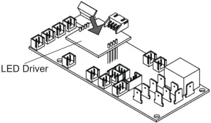
LED Driver Board Replacement
Will be required when updated MODs B and earlier of the CDFI-PROs and all MODs of the CDFI-Ps. The new LED Driver Board is included with new Main Control Boards..
Tools Required: Phillips head screwdriver
WARNING: Disconnect power before attempting any maintenance to reduce the risk of electric shock or damage to persons.
NOTE: Ensure that all of the components that contain water have been emptied and source water has been turned off before performing any maintenance.
- Follow the steps to access the main board on both sides of the cassette.
- Locate and disconnectthe the old LED driver board (Figure 6)
- Plug in the new LED driver board.
- Re-assemble the remainder of the cassette in reverse order from the instructions given in the “Main Control Board Replacement” instructions. Figure 6
Power Supply Replacement
Tools Required: Phillips head screwdriver
WARNING: Disconnect power before attempting any maintenance to reduce the risk of electric shock or damage to persons.
NOTE: Ensure that all of the components that contain water have been emptied and source water has been turned off before performing any maintenance.
Primary Side
- Disconnect and remove the media tray or log set from the unit and put them in a safe place.
- Remove the securing screws and metal wire cover at the end of both of the electronics covers.
- Remove the 4 screws and both of the electronics covers from the unit. (Figure 4)
NOTE: Use caution when removing the electronics cover, to prevent strain on the connector wire attached to it. - Remove the cable clamp, to allow for the assembly to be lifted out to better access the components.
- Holding the assembly at either end of the LED light strip, on the primary end, gently lift the electronics assembly out of the unit (Figure 4).
NOTE: There are several wires that run between the two sides, these wires will need to be gently removed through the opening on the secondary side to allow the primary electronics assembly to be lifted out. - Locate the power supply assembly.
- Transfer the wires from the old board to the new board.
NOTE: A flat head screwdriver can be used to gently pry between the end of the connector and the switch to release the wires. - Remove the old board from the unit and replace with the new board.
- Replace all of the wiring to their original locations and reinsert the electronics assembly.
CAUTION: Ensure that the switchboard and terminal block have not moved from their original locations and all wires are contained under the cover before reassembly. - Re-assemble the remainder of the cassette in reverse order from the instructions above.
Secondary Side
- Disconnect and remove the media tray or log set from the unit and put them in a safe place.
- Remove the 4 screws and the electronics cover from the unit. (Figure 4)
NOTE: Use caution when removing the electronics cover, to prevent strain on the connector wire attached to it. - Holding the assembly at either end of the LED light strip, on the primary end, gently lift the electronics assembly out of the unit (Figure 4).
- Locate the power supply assembly.
- Transfer the wires from the old board to the new board.
NOTE: A flat head screwdriver can be used to gently pry between the end of the connector and the switch to release the wires. - Remove the old board from the unit and replace with the new board.
- Replace all of the wiring to their original locations and reinsert the electronics assembly.
CAUTION: Ensure that the switchboard and terminal block have not moved from their original locations and all wires are contained under the cover before reassembly. - Re-assemble the remainder of the cassette in reverse order from the instructions above.
LED Light Assembly Replacement
Tools Required: Phillips head screwdriver
WARNING: Disconnect power before attempting any maintenance to reduce the risk of electric shock or damage to persons.
NOTE: Ensure that all of the components that contain water have been emptied and source water has been turned off before performing any maintenance.
Primary Side
- Disconnect and remove the media tray or log set from the unit and put them in a safe place.
- Remove the securing screws and metal wire cover at the end of both of the electronics covers.
- Remove the 4 screws and both of the electronics covers from the unit. (Figure 4)
NOTE: Use caution when removing the electronics cover, to prevent strain on the connector wire attached to it. - Remove the cable clamp, to allow for the assembly to be lifted out to better access the components.
- Holding the assembly at either end of the LED light strip, on the primary end, gently lift the electronics assembly out of the unit (Figure 4).
NOTE: There are several wires that run between the two sides, these wires will need to be gently removed through the opening on the secondary side to allow the primary electronics assembly to be lifted out. - Gently lift the LED light assembly off of the standoffs.
- Trace the control wire back to the main control board and replace with the wire from the new assembly.
- Install the new LED light assembly, ensuring that all of the wires are installed in the same location as the previous one.
- Replace all of the wiring to their original locations and reinsert the electronics assembly.
CAUTION: Ensure that the switchboard and terminal block have not moved from their original locations and all wires are contained under the cover before reassembly. - Re-assemble the remainder of the cassette in reverse order from the instructions above.
Secondary Side
- Disconnect and remove the media tray or log set from the unit and put them in a safe place.
- Remove the 4 screws and the electronics cover from the unit. (Figure 4)
NOTE: Use caution when removing the electronics cover, to prevent strain on the connector wire attached to it. - Holding the assembly at either end of the LED light strip, on the primary end, gently lift the electronics assembly out of the unit (Figure 4).
- Gently lift the LED light assembly off of the standoffs.
- Trace the control wire back to the main control board and replace with the wire from the new assembly.
- Install the new LED light assembly, ensuring that all of the wires are installed in the same location as the previous one.
- Replace all of the wiring to their original locations and reinsert the electronics assembly.
CAUTION: Ensure that the switchboard and terminal block have not moved from their original locations and all wires are contained under the cover before reassembly. - Re-assemble the remainder of the cassette in reverse order from the instructions above.
Heating Element Replacement
Tools Required: Phillips head screwdriver
WARNING: Disconnect power before attempting any maintenance to reduce the risk of electric shock or damage to persons.
NOTE: Ensure that all of the components that contain water have been emptied and source water has been turned off before performing any maintenance.
Primary Side
- Disconnect and remove the media tray or log set from the unit and put them in a safe place.
- Remove the securing screws and metal wire cover at the end of both of the electronics covers.
- Remove the 4 screws and both of the electronics covers from the unit. (Figure 4)
NOTE: Use caution when removing the electronics cover, to prevent strain on the connector wire attached to it. - Remove the cable clamp, to allow for the assembly to be lifted out to better access the components.
- Holding the assembly at either end of the LED light strip, on the primary end, gently lift the electronics assembly out of the unit (Figure 4).
NOTE: There are several wires that run between the two sides, these wires will need to be gently removed through the opening on the secondary side to allow the primary electronics assembly to be lifted out. - Locate the 2 screws that secure the element assembly (element and brackets) to the unit and remove.
- Lift the element assembly out of the unit.
- . Disconnect the element from the main control board.
- Remove the element from the mounting bracket and install the new element.
- Attach the new element to the main control board.
- Install and secure the element assembly into the unit.
- Replace all of the wiring to their original locations and reinsert the electronics assembly.
CAUTION: Ensure that the switchboard and terminal block have not moved from their original locations and all wires are contained under the cover before reassembly. - Re-assemble the remainder of the cassette in reverse order from the instructions above.
Secondary Side
- Disconnect and remove the media tray or log set from the unit and put them in a safe place.
- Remove the 4 screws and the electronics cover from the unit. (Figure 4)
NOTE: Use caution when removing the electronics cover, to prevent strain on the connector wire attached to it. - Holding the assembly at either end of the LED light strip, on the primary end, gently lift the electronics assembly out of the unit (Figure 4).
- Locate the 2 screws that secure the element assembly (element and brackets) to the unit and remove.
- Lift the element assembly out of the unit.
- Disconnect the element from the main control board.
- Remove the element from the mounting bracket and install the new element.
- Attach the new element to the main control board.
- Install and secure the element assembly into the unit.
- Replace all of the wiring to their original locations and reinsert the electronics assembly.
CAUTION: Ensure that the switchboard and terminal block have not moved from their original locations and all wires are contained under the cover before reassembly. - Re-assemble the remainder of the cassette in reverse order from the instructions above.
Level Sensor Assembly Replacement
Tools Required: Phillips head screwdriver
WARNING: Disconnect power before attempting any maintenance to reduce the risk of electric shock or damage to persons.
NOTE: Ensure that all of the components that contain water have been emptied and source water has been turned off before performing any maintenance.
Primary Side
- Disconnect and remove the media tray or log set from the unit and put them in a safe place.
- Remove the securing screws and metal wire cover at the end of both of the electronics covers.
- Remove the 4 screws and both of the electronics covers from the unit. (Figure 4)
NOTE: Use caution when removing the electronics cover, to prevent strain on the connector wire attached to it. - Remove the cable clamp, to allow for the assembly to be lifted out to better access the components.
- Holding the assembly at either end of the LED light strip, on the primary end, gently lift the electronics assembly out of the unit (Figure 4).
NOTE: There are several wires that run between the two sides, these wires will need to be gently removed through the opening on the secondary side to allow the primary electronics assembly to be lifted out. - Remove the refill bottle, top cover, transducer and sump.
- Locate the level sensor assembly. (Figure 7)
- Trace and disconnect the control wire for the level sensor assembly back to the main control board.
- Depress the two tabs along the one side of the assembly and slide the level sensor and wire out.
- Run new wire through to main control board.
- Install new level sensor.
- Reconnect the control wire.
CAUTION: Ensure that the switchboard and terminal block have not moved from their original locations and all wires are contained under the cover before reassembly. - Re-assemble the remainder of the cassette in reverse order from the instructions above.
Secondary Side
- Disconnect and remove the media tray or log set from the unit and put them in a safe place.
- Remove the 4 screws and the electronics cover from the unit. (Figure 4)
NOTE: Use caution when removing the electronics cover, to prevent strain on the connector wire attached to it. - Holding the assembly at either end of the LED light strip, on the primary end, gently lift the electronics assembly out of the unit (Figure 4).
- Remove the refill bottle, top cover, transducer and sump.
- Locate the level sensor assembly. (Figure 7)
- Trace and disconnect the control wire for the level sensor assembly back to the main control board.
- Depress the two tabs along the one side of the assembly and slide the level sensor and wire out.
- Run new wire through to main control board.
- Install new level sensor.
- Reconnect the control wire.
CAUTION: Ensure that the switchboard and terminal block have not moved from their original locations and all wires are contained under the cover before reassembly. - Re-assemble the remainder of the cassette in reverse order from the instructions above.
Sumps removed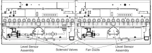
Figure 7
Solenoid Valve Replacement
Tools Required: Short Phillips head screwdriver
WARNING: Disconnect power before attempting any maintenance to reduce the risk of electric shock or damage to persons.
NOTE: Ensure that all of the components that contain water have been emptied and source water has been turned off before performing any maintenance.
Primary Side
- Disconnect and remove the media tray or log set from the unit and put them in a safe place.
- Remove the securing screws and metal wire cover at the end of both of the electronics covers.
- Remove the 4 screws and both of the electronics covers from the unit. (Figure 4)
NOTE: Use caution when removing the electronics cover, to prevent strain on the connector wire attached to it. - Remove the cable clamp, to allow for the assembly to be lifted out to better access the components.
- Holding the assembly at either end of the LED light strip, on the primary end, gently lift the electronics assembly out of the unit (Figure 4).
NOTE: There are several wires that run between the two sides, these wires will need to be gently removed through the opening on the secondary side to allow the primary electronics assembly to be lifted out. - Remove the refill bottle, top cover, transducer and sump.
- Locate the solenoid valve to be replaced. (Figure 7)
- Trace and disconnect the control wire for the solenoid back to the main control board.
- Remove the two screws from the front face of the bracket to release the valve.
- Disconnect the plumbing connections and remove the solenoid valve
- Run new wire through to main control board.
- Install new solenoid valve.
- Reconnect the control wire.
CAUTION: Ensure that the switchboard and terminal block have not moved from their original locations and all wires are contained under the cover before reassembly. - Re-assemble the remainder of the cassette in reverse order from the instructions above.
Secondary Side
- Disconnect and remove the media tray or log set from the unit and put them in a safe place.
- Remove the 4 screws and the electronics cover from the unit. (Figure 4)
NOTE: Use caution when removing the electronics cover, to prevent strain on the connector wire attached to it. - Holding the assembly at either end of the LED light strip, on the primary end, gently lift the electronics assembly out of the unit (Figure 4).
- Remove the refill bottle, top cover, transducer and sump.
- Locate the solenoid valve to be replaced. (Figure 7)
- Trace and disconnect the control wire for the solenoid back to the main control board.
- Remove the two screws from the front face of the bracket to release the valve.
- Disconnect the plumbing connections and remove the solenoid valve.
- Run new wire through to main control board.
- Install new solenoid valve.
- Reconnect the control wire..
CAUTION: Ensure that the switchboard and terminal block have not moved from their original locations and all wires are contained under the cover before reassembly. - Re-assemble the remainder of the cassette in reverse order from the instructions above.
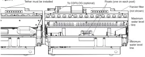
Figure 8
Troubleshooting Guide
Before you begin consulting the troubleshooting guide, see Figure 8 to ensure the unit is ready for operation. The water level must be between the minimum and maximum water level lines, and the tether must be plugged in. When turning the unit on, ensure that both the power switch has been turned to the ON (I) position and that the standby button has been pressed.
| SECTION | PROBLEM | CAUSE | SOLUTION |
| 1.0 | General | ||
| 1.1 | Fireplace does not turn on manually (unit does not beep when switch is engaged) | No incoming voltage | Check Fuse/Breaker Panel |
| If multiple units are installed on the same circuit, ensure they are wired in parallel. | |||
| Defective main control board | Replace main control board | ||
| Defective electronic choke (primary side) | Replace electronic choke | ||
| Defective power supply (unit may beep repeatedly to indicate error) | Replace power supply | ||
| Defective fuse – typically due to insufficient air intakes | Correct air intake issues, and replace fused wire harness. | ||
| 1.2 | Only one side of the unit is operating | Tethered controller not installed correctly | Ensure that connection has clicked into place and red light is visible. If there is no light, replace tether. |
| No power when standby button is pressed | Refer to section 1.1 for the secondary side | ||
| 1.3 | Fireplace does not turn on with the Remote Control | Improper operation | Refer to Operation Section |
| The batteries in the remote control are dead | Install new battery into the remote control | ||
| Tethered controller not installed correctly | Ensure that connection has clicked into place and red light is visible. | ||
| Remote not synchronized with the unit | Synchronize remote to unit. Unit will flash on and off during synchronization, completion will be indicated with 5 beeps | ||
| Remote signal is not being received by tethered controller | Ensure that tethered controller is in an open area that can receive signal from remote control | ||
| Defective remote control (blue light on end of remote does not turn on when buttons are pressed) | Replace remote control | ||
| 1.4 | LED lights not turning on | Defective LED light strip | Replace LED light strip |
| 1.5 | Noise when unit is on standby | Some buzzing is normal | If there is excessive noise, replace power supply |
| 1.6 | Unpleasant smell when unit is used. | Dirty or stale water. | Clean the unit as described under Maintenance. |
| 1.7 | Water is appearing around the unit | During normal operation it is expected to see some condensation of water on the media tray. | If condensation is present ensure that mist out- lets are unobstructed |
| Certain ambient conditions will cause condensation on the unit and in most cases will only occur on initial start up of the unit | |||
| If there is excessive water, refer to section 4.1 | |||
| 2.0 | Blinking (error codes)* | ||
| 2.1 | Unit continuously blinks one time | Water level in the sump is too high | Remove enough water from reservoir so that level is below maximum level. |
| If the problem persists, see section 4.5 | |||
| 2.2 | Unit continuously blinks twice | Water level in the sump is too low | Refill the water reservoir so that level is above the minimum level |
| If the problem persists, see section 3.7 if using bottles or section 4.3 if using direct water line | |||
| 2.3 | Unit continuously blinks three times | Defective level sensor assembly | Replace level sensor assembly |
| 2.4 | Unit continuously blinks four times | Water is refilling too slowly | Turn unit off with the main power switch. Wait 60 seconds before turning back on. |
| If problem persists, clean water filter and inspect plumbing to make sure pressure is adequate and nothing is obstructing water flow. | |||
| 3.0 | Flame | ||
| 3.1 | The flame effect has too much smoke or is coming out too fast | Flame effect control is set too high | Adjust the flame height on both the secondary and/or primary controls |
| Filter is missing off of fan housing | Insert fan filter | ||
| 3.2 | Mist is not coming out evenly | Condensation building up on the mist outlet | Remove the build up of condensation |
| Unit is not level | Adjust the feet under the unit to ensure that the unit has been installed level, front to back and side to side | ||
| Media is blocking air flow | Rearrange media to ensure mist outlet is not being blocked | ||
| The transducer is not operating correctly – put the unit in test mode to test the transducer | If the transducer is running, ensure that the emitter is clean and free of calcium deposits or scaling | ||
| If the transducer is not running, replace the transducer with the provided additional transducer | |||
| If using demineralized water, unit will not produce a consistent mist | Add 1/8 tsp of table salt to water reservoir to introduce electrolytes, only repeat when mist is not being produced correctly | ||
| Water in unit is too cold | Allow water to warm to room temperature. | ||
| 3.3 | The flame effect is too low | Flame effect control is set too low | Adjust the flame height on both the secondary and/or primary controls |
| Insufficient air intake | Enlarge area for air to enter unit in such a way that it will reach the bottom. Refer to to installation guide for requirements. | ||
| Transducer is defective | Replace transducer | ||
| Flame is not rising | Refer to section 3.5 | ||
| 3.4 | Flame appears to be rolling back into the unit | Insufficient air intake | Enlarge area for air to enter unit in such a way that it will reach the bottom. Refer to to installation guide for requirements. |
| The heating element is not operating correctly- put unit in test mode to test the operation of the heating element | If no click is heard from the relay, replace the main board | ||
| If a click can be heard, but the element does not get warm, replace the heating element | |||
| 3.5 | Mist is being produced under the top cover, but does not rise to create a flame effect | Cord is located over emitter on transducer | Relocate cord so that mist is free to rise off of transducer |
| Transducer is not installed correctly | Ensure that the connection has clicked into place, and that transducer is seated correctly | ||
| Water in fan duct | Ensure there is no water in the duct that blows air up to the flame | ||
| Fan is not operating correctly – put unit in test mode to test the fan | Ensure fan filter is clean and dry | ||
| If fan is not working in test mode, replace fan. If issue persists, replace main board | |||
| 3.6 | Flame effect will not start, no error blinks | Improper operation | Mist will begin emitting out of the unit after 45 seconds of operation |
| Flame is being produced, but is not rising beyong the top cover. | Carefully lift the top cover while the unit is operating. If mist is produced but is not rising, refer to section 3.5. | ||
| The transducer is not operating correctly- put the unit in test mode to test the transducer | If the transducer is running, ensure that the emitter is clean and free of calcium deposits or scaling | ||
| If the transducer is not running, replace the transducer with the provided additional trans- ducer | |||
| 4.0 | Water Supply | ||
| 4.1 | Sump is not filling- refill bottle | Bottle is tilting away from fill cap | Ensure unit is level. Place under the bottle to slope it slightly toward the fill cap so that the water can easily flow to the water reservoir |
| 4.2 | Sump is overfilling – refill bottle | Bottle or bottle cap is leaking | Inspect the bottle and cap for damage and replace if necessary. |
| 4.3 | Water is appearing beneath unit | Connections are leaking | Ensure that all water connections are tight and fully inserted |
| Incoming water pressure is too high | Reduce water pressure to below 58 psi (8 bar) | ||
| 4.4 | Unit is underfilling or not filling (hard plumbed to water source) | Unit is not level | Ensure that unit is level to allow an accurate reading of water level |
| Valve not open | Ensure that the ball valve of the unit is open, and that water is getting to the unit | ||
| Missing floats | Inspect sump to ensure floats are installed | ||
| Defective level sensor assembly | Replace level sensor assembly | ||
| The solenoids are not operating correctly – put unit in test mode to test the operation of the solenoids | If the solenoids are not working, replace the solenoid | ||
| 4.5 | Unit is not refilling and is not giving error blinks when water is too high or too low | Defective level sensor assembly | Replace level sensor assembly |
| 4.6 | Sump is over filling. | Plumbing cap is leaking when orange cap is removed, indicating a defective solenoid | Can try flushing the solenoid by connecting water line in the opposite direction |
| Replace solenoid | |||
| For additional troubleshooting relating to the CDFI-BX Pro-Box, refer to its service manual. | |||
After the unit has shut down due to an error, a full reset of the unit will be required by turning the unit Off with the On/Off switch for 60 seconds then turning back On.
Test Mode
Test Mode has been integrated into this product to improve end-of-line testing during production and can be used to isolate components for individual function testing. Test mode should be conducted by trained personnel only. The icons on the On Board Control buttons (Figure 1) do not match the commands they are associated with, when in test mode.
- Ensure unit is connected to power and water is supplied.
- Remove logs or top plate and set aside.
- Press power switch on (Figure 1A). Presence of power will be indicated by one beep
- Press the troubleshooting button
 (Figure 1D) on the side that the testing is required, unit will beep.
 - Press the following buttons to test functionality of listed components – press once will turn On and press again to turn off
Component Test Expected Functionality 
LED Assembly / LED Driver Lights turn on 
Sound Crackling sound turns on 
Fan Fan turns on 
Transducer Transducer will turns on and bubbling will be seen coming out of the transducer Solenoids Solenoids will turn On (the main solenoid coming in and the solenoid on the side being tested). The sound of the solenoids can be heard (a slight thump), and possibly the sound of water flowing. 
Heater Relay Relays will be activated to turn the heating element on, a quiet clicking noise can be heard. The element will get warm. 
Log Set LEDs in log set will turn on (if present) - After 15 seconds of inactivity the unit will beep and then return to regular Standby mode, or the On/Off button can be switched to Off to end the test mode.


Ph: 1-888-346-7539 | www.dimplex.com
In keeping with our policy of continuous product improvement, we reserve the right to make changes without notice.
© 2020 Glen Dimplex Americas