ENSTO AVR400 Elektroskandia Sweden AB
Operation instruction
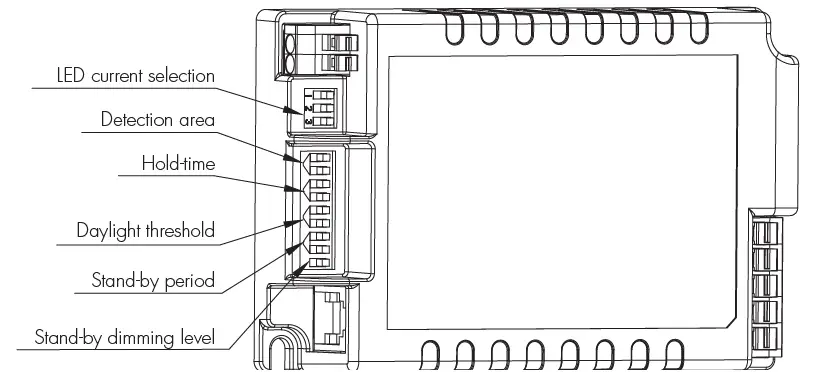
LED current selections
The current can be easily configured by choosing the correct combination of the DIP switches (see table below).
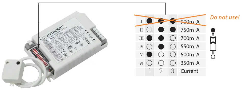
| AVR400 SDIM lumen output table | |||
| Current | Power | Luminous flux (4K) | Luminous flux (3K) |
| AVR400.SDIM, 350mA | 13W | 1600 lm | 1480 lm |
| AVR400.SDIM, 500mA | 18W | 2260 lm | 2090 lm |
| AVR400.SDIM, 550mA | 20W | 2450 lm | 2260 lm |
| AVR400.SDIM, 700mA | 25W | 3010 lm | 2790 lm |
| AVR400.SDIM, 750mA | 27W | 3200 lm | 2960 lm |
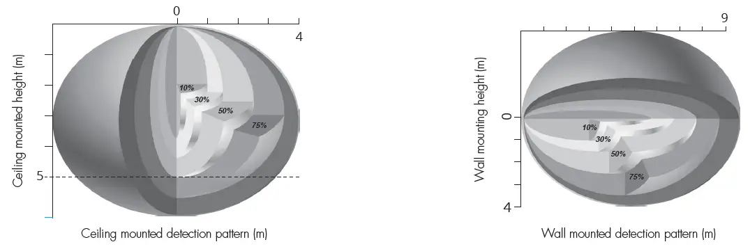
Recommended installation heights
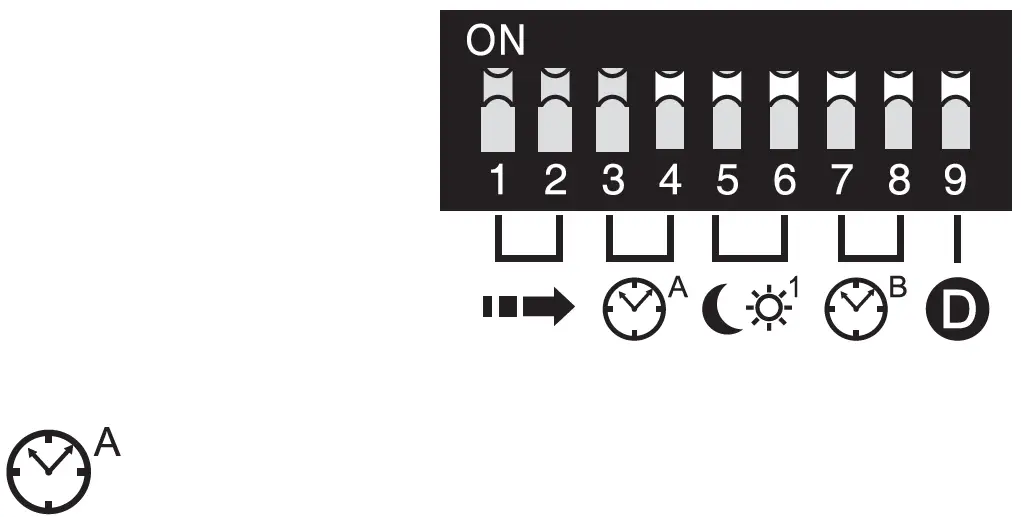
DIP Switch Settings
Detection Area
Sensor sensitivity can be adjusted by selecting the combination on the DIP switches to fit precisely for each specific application. Note: by choosing “Sensor OFF”, it becomes an ordinary driver without occupancy detection.
Daylight
Set the level according to the fixture and environment. The light will not turn on if ambient lux level exceeds the daylight threshold preset.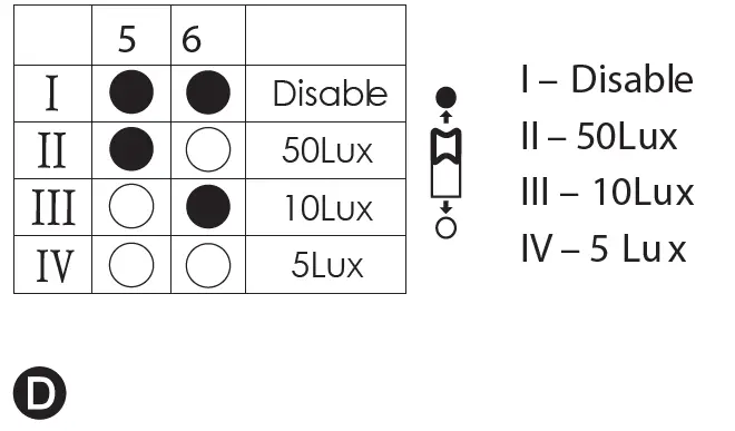
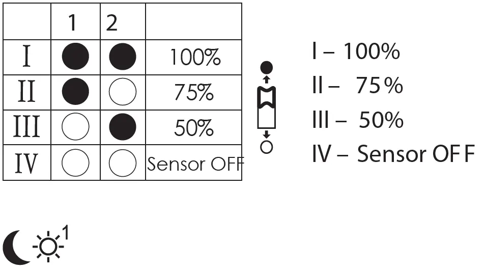
Stand-by Dimming Level
The setting is used to select the desired dimmed light level used in periods of absence for enhanced comfort and safety.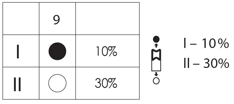
Hold Time
Select the DIP switch conjuration for the light on-time after presence detection. This function is disabled when natural light is sufficient. Note: this function is disabled when the natural daylight exceeds the daylight threshold IV setting for more than 5 minutes.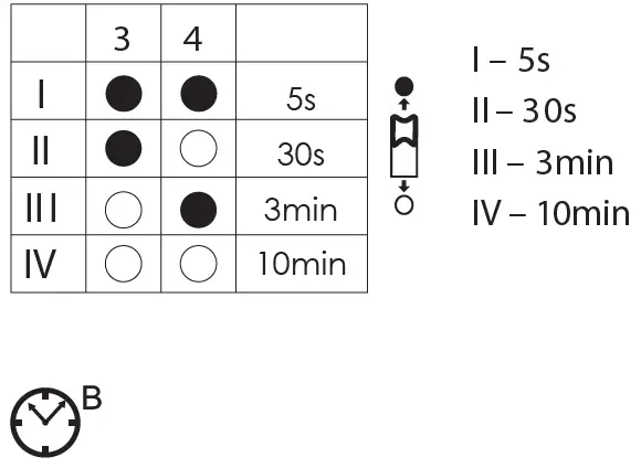
Stand-by Period
This is the time period you would like to keep at the low light output level before it is completely switched off in the long absence of people. Note: “0s” means on/off con-trol; “+∞” means the stand-by period is infinite and the light is effectively controlled by the daylight sensor, off when natural light is sufficient and automatically on at dimming level when insufficient.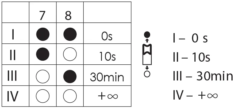
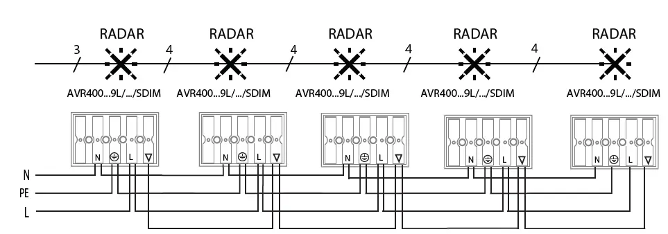
AVR400 SDIM TUTKAVALAISIMEN KYTKENTÄESIMERKKI KOPPLINGSEXEMPEL MED AVR400 SDIM RADAR – ARMATUREN WIRING DIAGRAM OF AVR400 SDIM RADAR LUMINAIRE