VIOTEL Version V1.0C Smart Barrier User Manual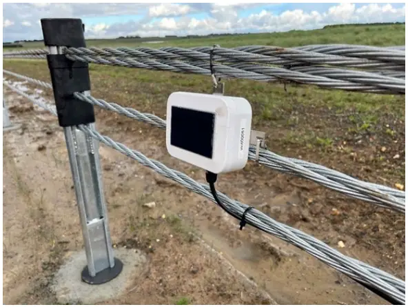
Introduction
Warning
This guide intends to assist in the preferred mounting, operation and usage of Viotel’s Smart Barrier Node. Please read and completely understand this user guide in order to make sure the safe and correct use of the system as well as maintain the longevity of the device.
Please read and completely understand this user guide in order to make sure the safe and correct use of the system as well as maintain the longevity of the device.
Protection provided by the equipment may be impaired if used in a manner contrary to this user manual.
Changes or modifications not expressly approved by Viotel Limited could void the user’s authority to operate the equipment.
This product must not be disposed of in the normal waste stream. It contains a battery pack and electronic components and so should be recycled appropriately.
Parts List
| PART | QTY | DESCRIPTION | 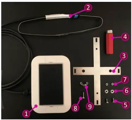 |
| 1 | 1 | Smart Barrier Node with integrated solar panel | |
| 2 | 1 | Strain Band | |
| 3 | 1 | SS Mounting Bracket | |
| 4 | 1 | Magnet | |
| 5 | 2 | M3x8mm PH1 bolt | |
| 6 | 2 | M3 Washer | |
| 7 | 2 | M3 hex nut | |
| 8 | 1 | M3x 12mm 2.5 hex head bolt | |
| 9 | 1 | M3 butterfly/nyloc nut |
Required Tools
Tools may be required specific to your installation scenario. Common tools include:
- 2.5mm Hex key
- M5.5mm x 50mm hex nut driver
- Coil spring compressor clamp (or similar)
- Zip ties (plastic & stainless steel)
Usage
Recommended Mounting Procedure
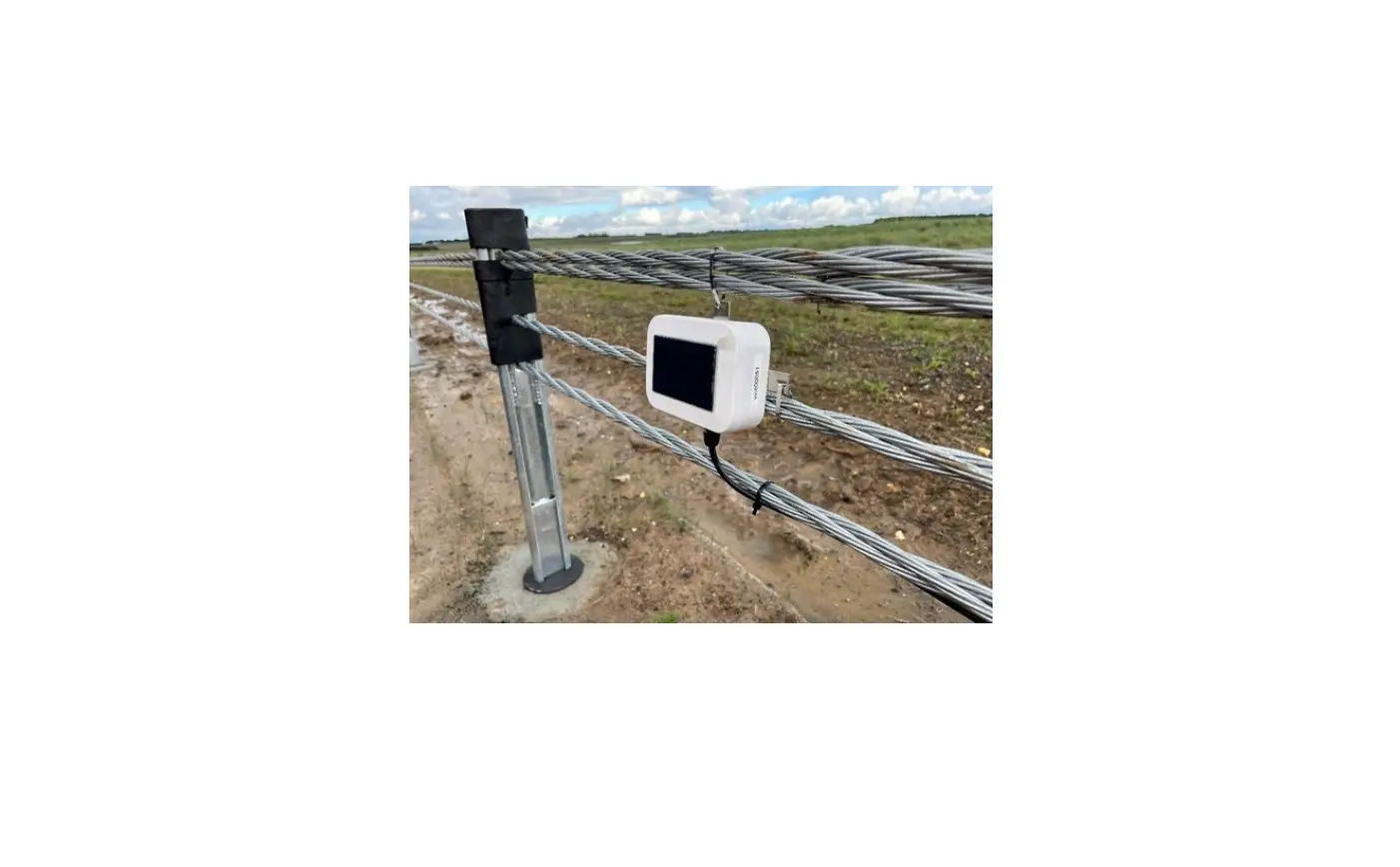
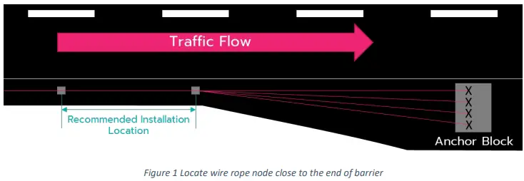
It is highly recommended that the Viotel SMART Barrier Node be installed on the last full barrier section before the anchor block downstream of the flow of traffic. The device can efficiently detect strain and crashes along the entire length of the barrier from this position.
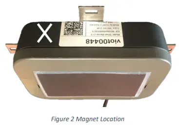
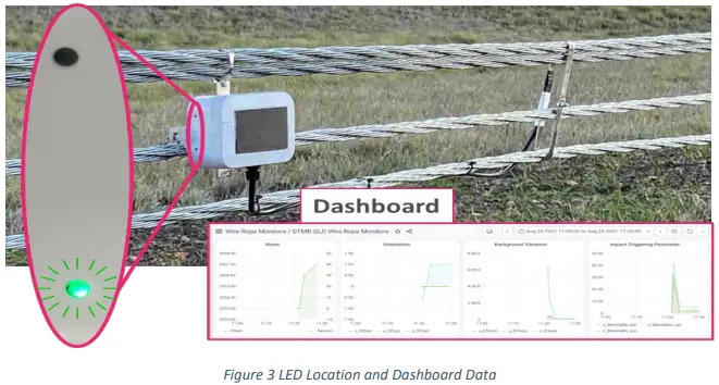
Indicated Key Location
Wherever instructed to tap the node using the magnet, do so at the spot indicated “X”. Sequential taps must be performed within 3 seconds before the device count resets.
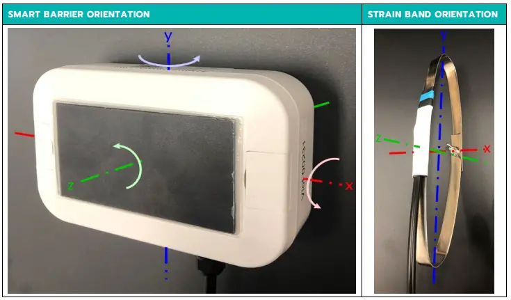
Mounting Orientation (Recommended)
It is important to position the solar panel on the side of the barrier for maximum sun exposure. In Australia and New Zealand then is a northerly aspect and consideration should be given to position of overhead structures and trees that throw shade during the date (particularly if the installation occurs at night with road lane closures).
Mount Bracket to Device
| STEP | DESCRIPTION |
| 1 | Remove all components from their packaging |
| 2 | On the Smart Barrier Node (Part 1); find and open the top and lower flaps.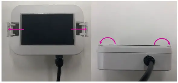 |
| 3 | Align the mounting holes seen underneath the flaps on the node (Part 1) with the holes on the top side of the stainless-steel mounting bracket (Part 3). |
Feed a bolt (Part 5) through the aligned hole from under the bracket. With the bolt’s seen through the node (Part 1), place a washer (Part 6) and tighten a bolt (Part 7) on. Repeat this process until the smart barrier node (Part 1) is firmly attached to the bracket (Part 3).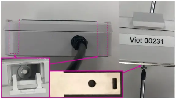 |
Standard Wire Rope Installation
| STEP | DESCRIPTION |
| 1 | Using a tool like coil spring compressor clamp: compress both the top and bottom wire ropes. If mounting on highly angled wire ropes, it is recommended that hose clamps be installed to support the gauge band (Part 2). Follow steps listed in the 2.6 Anchored Wire Rope Installation (Not Recommended) section before proceeding to Step 2. 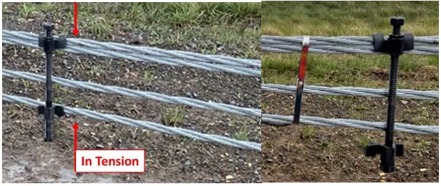 |
| 2 | Wrap the strain band (Part 2) around the compressed wires. Feed the bolt (Part 8) through the aligned holes in the back of the band (Part 2) and tighten the butterfly/nyloc nut (Part 9). The tool/coil spring compressor can now be slowly released. If attached to non-parallel wires; ensure the gauge band (Part 2) is supported by hose clamps on the wire rope (see the 2.6 Anchored Wire Rope Installation (Not Recommended) section for details). |
| 3 | Using steel ties, attach the smart barrier node (Part 1) to the wire rope barrier ensuring at least three points of contact. Zip-tie the band-cable (Part 2) along the lower wire rope. It is recommended the node (Part 1) is mounted onto the wire rope; however, it can be attached to posts if needed. 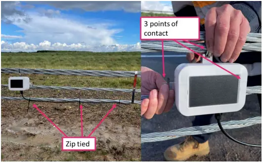 |
Anchored Wire Rope Installation (Not Recommended)
| STEP | DESCRIPTION |
| 1 | Locate the top and bottom wires in the wire rope barrier on the side of the anchor block. Using a tool like coil spring compressor clamp: compress both the identified top and bottom wire ropes.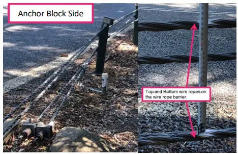 |
| 2 | Install hose clamps on the side of the strain band closest to the anchor block, to prevent band slipping down the wires. |
| 3 | Proceed to steps 2 and 3 listed in the 2.5 Standard Wire Rope Installation section.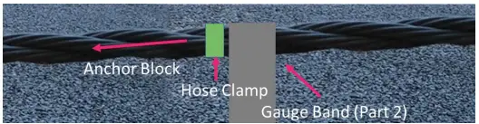 |
Operating Instructions
Operation
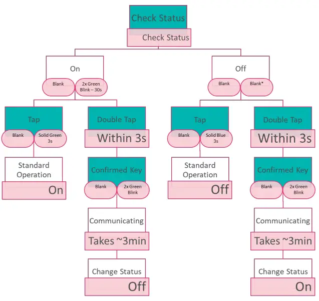
By default, your Viotel Smart Barrier Node will be set to Off. To change the mode that the smart barrier node is in; simply take the magnet (Part 4) and double tap it over the Indicated Key Location.
A double green blink every 30s on status LED (lower) will indicate that the device is now On.
All operations and LED indications refer to firmware version: 02.02.00, please be aware future states may change some functionality.
| TAP INSTRUCTIONS | FUNCTION | DESCRIPTION |
| Tap once (while) | Current Status | This will light up the LED indicating the current status that this system is in. |
| Tap once, Tap again within 3 seconds | Upload and change status | This will cause the device to initiate the upload and update sequence. In total; this process should take a few seconds to complete and then set the device automatically to a new status. |
System Status
| STATUS | DESCRIPTION |
| On | In this status, the device will consistently record data given the user defined interval, check for firmware updates, monitor for user defined triggers and check for Magnet inputs (Part 4). |
| Communicating | The device is currently trying to communicating with the server to update firmware, load data and status information. The Comms LED (Upper) will go through four stages: Stage 1. Attempting Communications & Check for Updates: indicated by Green Blink every second. |
| Stage 2. Link Established & Communicating Correctly: indicated by Three Blue Blinks. Stage 3. Firmware Updates: indicated by Green Blink or Red/Green Blink (see 3.3 System Communications Indicator (Upper LED) for details). Communication Complete: indicated by Solid Aqua. | |
| Off | The device will check for any wake-up commands, such as the Magnet (Part 4) or user defined data collection interval. If there is enough power for the device to be On, it will be indicated by Blue Blink Twice every 30 seconds. Every 7-days, the device will initiate a connection to provide status updates and check for system updates. Then it shall return Off unless otherwise specified by the server. |
Table 3 Description of device System Status
Changes depending on battery level. See Off Mode in the System Status section for details.
Figure 4 Flow Diagram for Cycling System Status with Magnet
System Communications Indicator (Upper LED)
Please refer to table below in conjunction with section 3.2 for details.
| LIGHT | INTERVAL | MEANING | DESCRIPTION | VISUAL |
| Green Blink | 1s | Communicating | Stage 1 (see 3.2 System Status for details). |  |
| Three Blue Blinks | 3s apart | Communicating | Stage 2 (see 3.2 System Status for details). |  |
| Green Blink | N/A | Communicating | The Link has been established and there are no firmware updates. |  |
| Red/Green Blink | Alternating every few seconds | Communicating | The node is undergoing a firmware update. It will resume previously set operation shortly. |  |
| Blank | N/A | No Activity | The device is not communicating. |  |
| Yellow Blink | N/A | Acquiring GPS | The device is currently obtaining its GPS coordinates. This occurs once per day. |  |
| Red Blink | 1s | Communication Issue | The smart barrier node cannot connect to the server. |  |
Table 4 System Status Indicator
System Status Indicator (Lower LED)
Please refer to table below in conjunction with section 3.4 for details.
| LIGHT | INTERVAL | MEANING | DESCRIPTION | VISUAL |
| Green Blink Twice | 30s | On – Normal Operation | See 3.2 System Status for details. |  |
| Green Blink | 2s (after second tap) | Confirmed Key Input | This indicates that the device has detected the key and will begin its next process. |  |
| Blank | N/A | No activity | The Device is currently in Off status. |  |
| Red Blink | 1s | GPS Timeout | The GPS was unable to connect and has timed out. |  |
| Blue Blink Twice | 30s | Off* | The device is currently in Off mode, however there is enough power to safety run in On mode. |  |
| Solid Blue | 3s (after key tap) | Off | See 3.2 System Status for details |  |
| Solid Aqua | 3s | Communicating | See 3.2 System Status for details |  |
Table 5 System Communications Indicator
Maintenance
The product should not require any maintenance after installation. Only service personnel authorised by the manufacturer may open the inner enclosure. No user serviceable parts are located inside.
Cleaning
If the need to clean the product should arise, use only a damp cloth and mild detergent. Do not use any solvents as this may damage the enclosure.
Downloading Data
The only way to retrieve data is over the cellular communications. This can be activated on demand using the magnet. However, if the device is in the field and is unable to upload data, the device is programmed to keep trying in decreasing increments to conserve battery. If after 4 days of attempting to upload, it will reboot.
Data is stored on non-volatile memory; therefore, it is stored when rebooted and after power loss.
Data is deleted from the device once successfully uploaded.
Further Support
For further support, please email our friendly staff at [email protected] with your name and number and we will get back to you.
Viotel Offices
Sydney
Suite 3.17, 32 Delhi Road
Macquarie Park, NSW, 2113
Auckland
Suite 1.2, 89 Grafton Road
Parnell, Auckland, 1010
Remote Offices: Brisbane, Hobart
Remote Offices: Brisbane, Hobart
[email protected] | viotel.co


