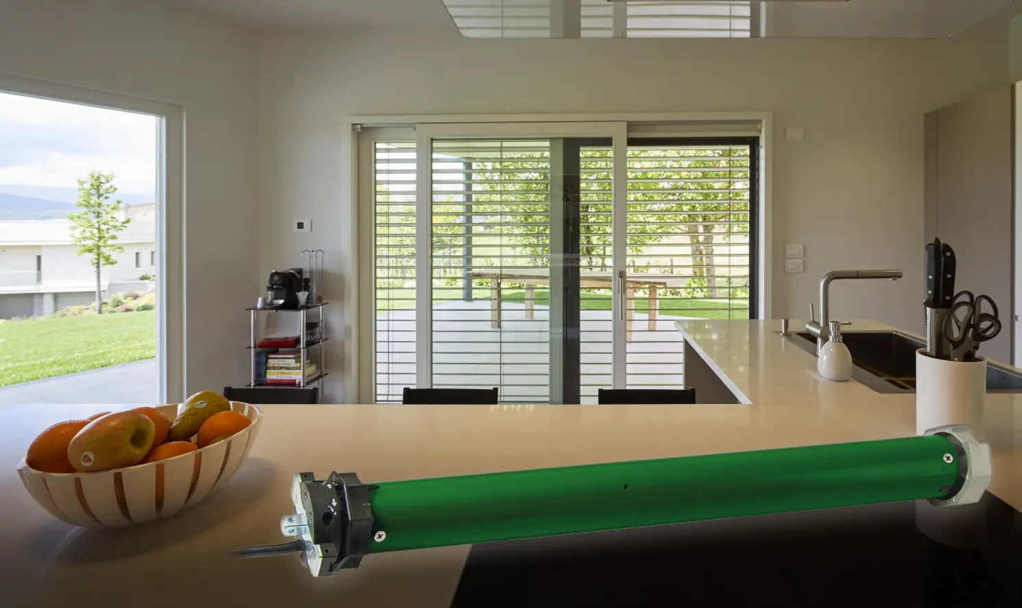
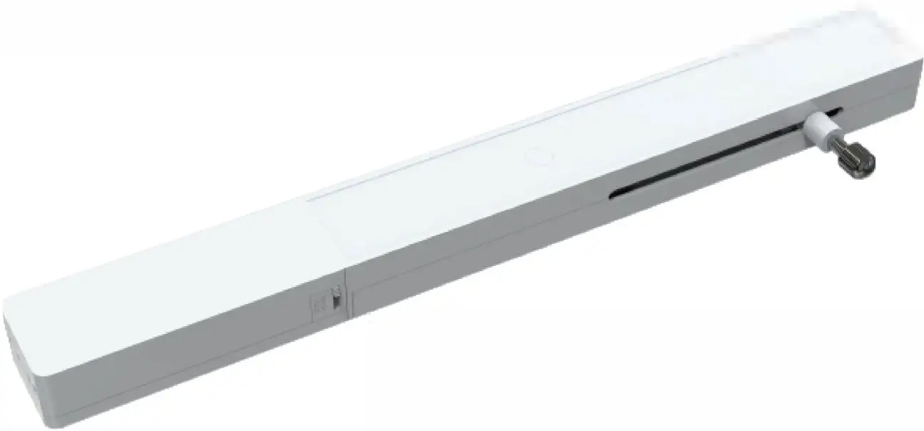
AM20 Plantation Shutter Motor
Motor Features
- User friendly removable battery case; accept 5V type-C USB charging
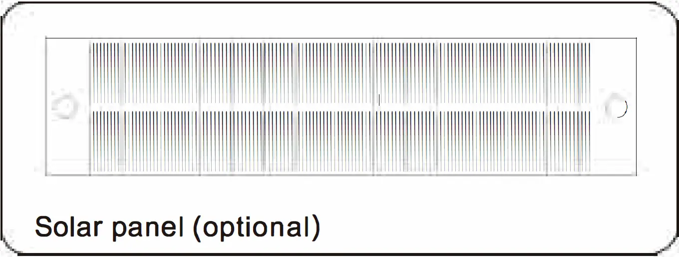
- Built-in 900mAh rechargeable lithium battery. Motor can connect with solar panel extending running time.
- Compatible both Bluetooth bi-directional communication control and radio frequency remote control.
- Featuring rational light tilting mode and one touch tap-to-run mode.
- The push/pull force is up to 50N (5kgs).
- Running speed 8mm/s, quick response.
- Various fixed methods are available, screws fixed and 3M adhesive tape.
Motor Specification
Push/ Pull Power | Running Speed | Running Distance | Rated Power | Charging Voltage | Battery Capacity | Standby Time | RF Frequency | IP Class | Operating Life | Working Temperature |
| 50N | 8mm/s | 0-82mm | 2W | 5VDC | lithium battery 900mAh | 3 months (It is recommended to charge every three months) | 433.92MHz | IP 32 | 15000 times | -10°c -+ss0c |
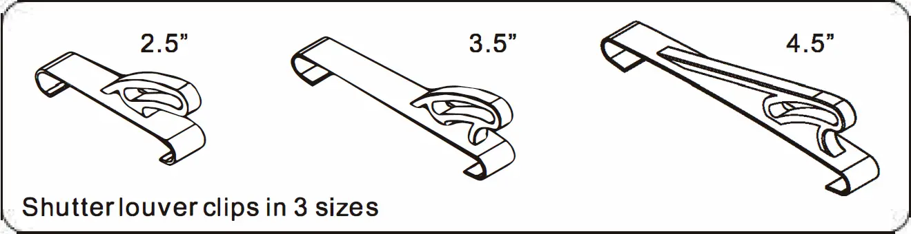
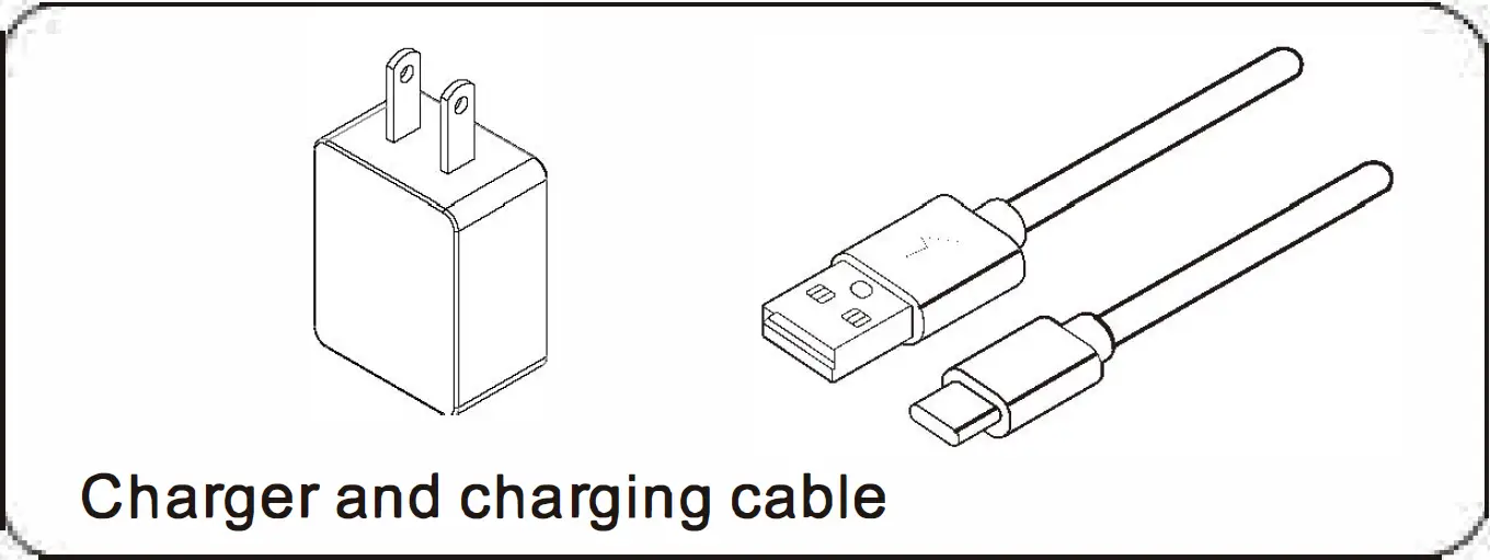
Accessory
Installation Instructions
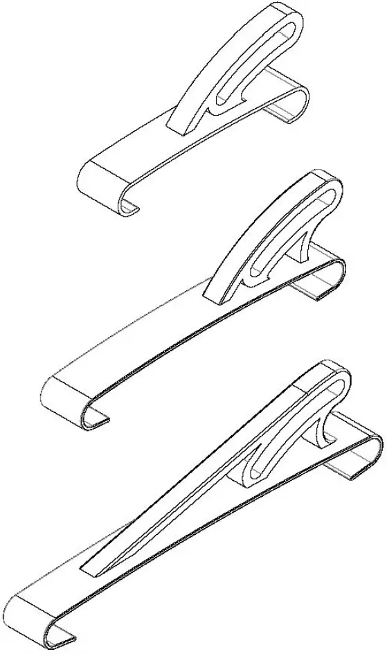
Shutter Louver Clips Installation Method
In order to achieve better light blocking effect, the clip is recommended to install onto the middle louver of the shutter.
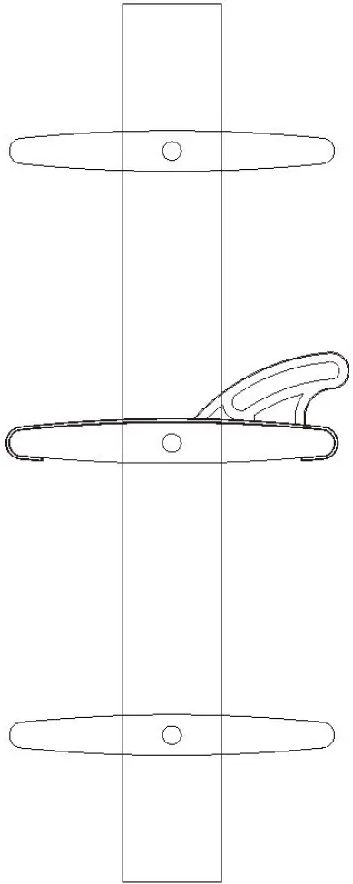
- Choose the hook with right size.

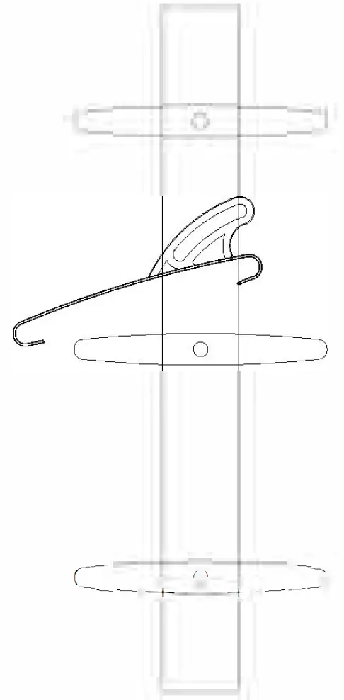
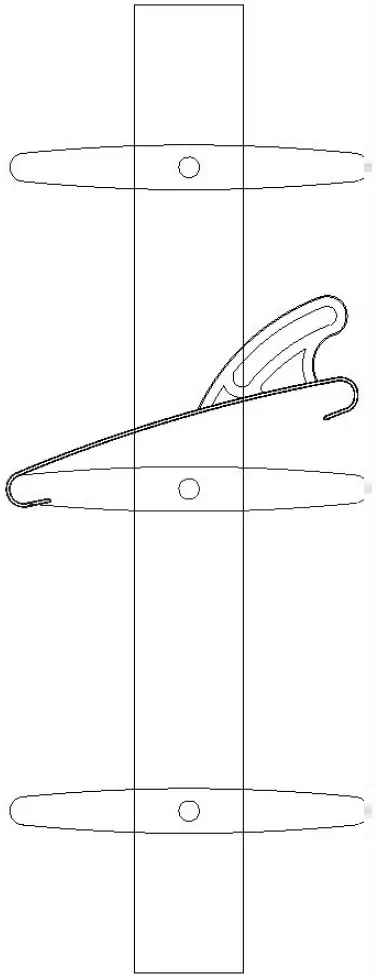
- Rotate shutter louver to a horizontal level.

- Put the clip on the louver, there are two sides of the hook, the longer side attach to the louver first.

- Make the shorter side attach to the louver, make sure the two sides of clip are well attached to louver.

- The clip is well installed now.

Plantation Motor Installation Method
Preparation
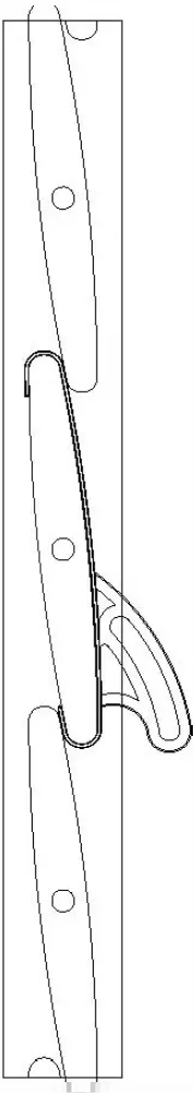
- When the clip is well installed, make the shutter louvers fully closed.
- The driving rod of the motor should run to the lowest limit (the default limit of the motor is lower limit), and insert the rod to the arc-shaped hole of the hook.
- Pull the motor straightly down, make sure the shutter louvers are tightly closed, and mark down the position of the motor.
Fixed the Motor
Method 1: Screw Fixed
- Fix the motor onto shutter and mark position.
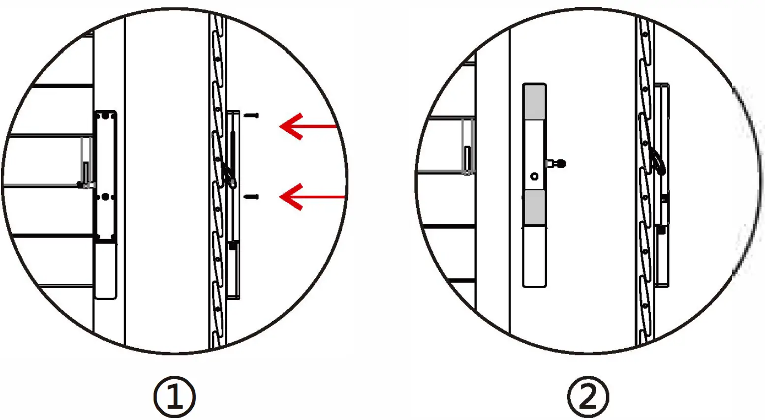
- Use Phillipe screwdriver to fix two screws on the motor (like the right picture (1)), the screws are in the accessory kit package.
- Attached the clip to motor rod, lock the screw nuts.
- Press the two screw caps into the screw holes, Motor installation completed.
Method 2: 3M Adhesive Tape Fixed
- Put the 3M adhesive tape on motor (like right picture (2)), don’t attach the adhesive tape on battery pack.
- Install the motor on the marked position.
- Attached the clip to motor rod, lock the screw nuts.
- Press the two screw caps into the screw holes, Motor installation completed.
Operating Instructions
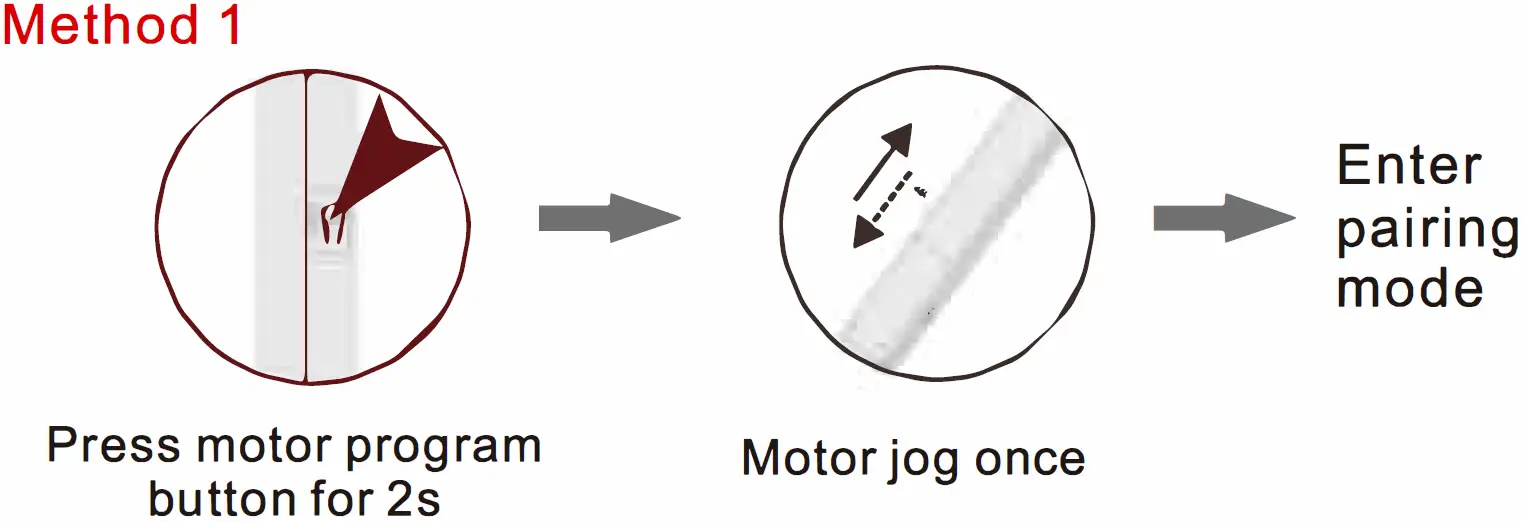
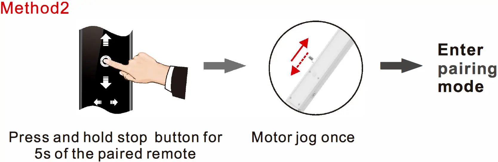
Enter Pairing Mode
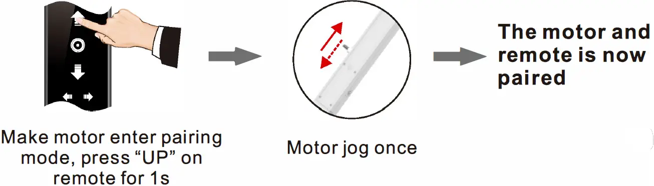
Pair to Remote
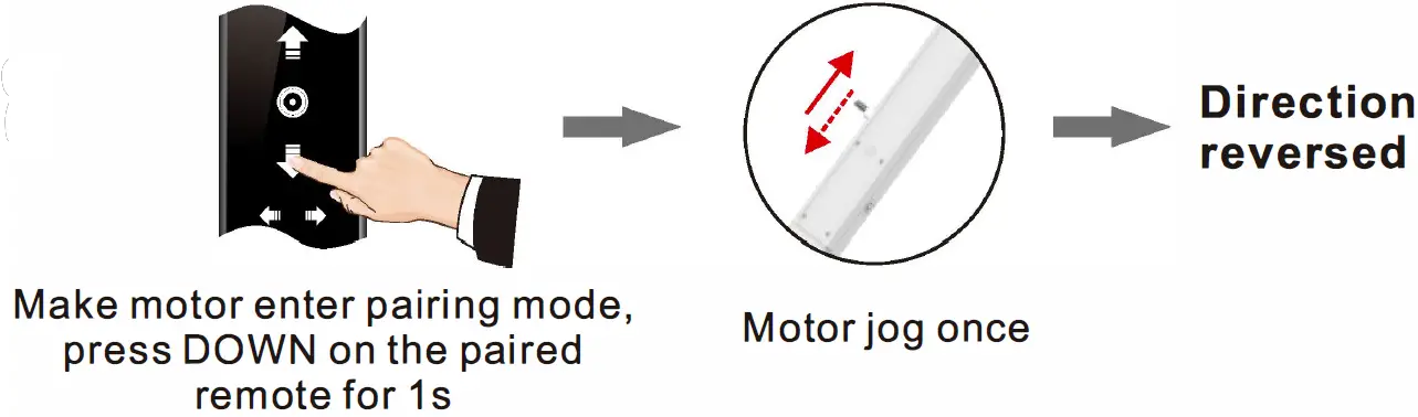
Reverse Motor Direction
Switch Light Tilting Mode and Tap-to-Run Mode
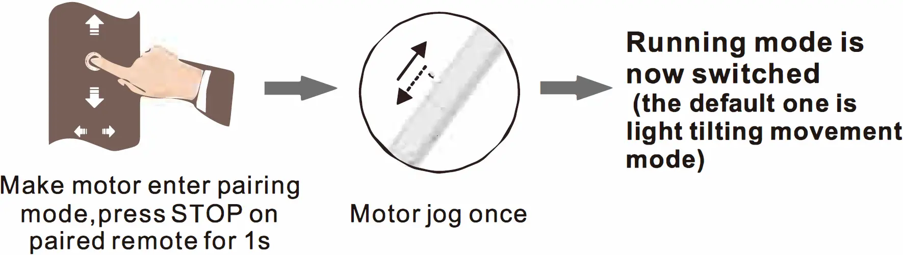
- In tap-to-run mode, if middle limit has been set, the motor will stop on middle limit, press UP or DOWN, motor will move to next limit position.
- In light tilting mode, short press UP/DOWN, motor will only tilt in rational angel, while long press UP/DOWN >2s, the motor will run continuously. If middle limit has been set, the motor will stop on middle limit.
Movement Calibration Function (One Short Press + One Long Press)
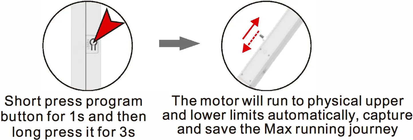
Movement Calibration Function: Automatically capture and save physical upper and lower limits, this will help to protect the motor case. When motor is in movement calibration mode, the push/ pull power will be reduced so that motor can be easier to record the max journey. it’s recommended to calibrate the journey each time before installation in no-load condition.
Delete Single Channel

Delete All Memories

Adjust Upper / Lower Limits
When movement calibration finished, the default upper limit is max journey calibration, and the lower limit is minimum journey calibration.