![]() SuperWorkstation
SuperWorkstation
5049A-TR
5049A-TR Tower Barebone Single Processor
 USER’S MANUAL
Revision 1.0
The information in this user’s manual has been carefully reviewed and is believed to be accurate. The vendor assumes no responsibility for any inaccuracies that may be contained in this document and makes no commitment to update or to keep current the information in this manual, or to notify any person or organization of the updates. Please Note: For the most up-to-date version of this manual, please see our website at www.supermicro.com.
Super Micro Computer, Inc. (“Supermicro”) reserves the right to make changes to the product described in this manual at any time and without notice. This product, including software and documentation, is the property of Supermicro and/ or its licensors, and is supplied only under a license. Any use or reproduction of this product is not allowed, except as expressly permitted by the terms of said license.
IN NO EVENT WILL Super Micro Computer, Inc. BE LIABLE FOR DIRECT, INDIRECT, SPECIAL, INCIDENTAL, SPECULATIVE, OR CONSEQUENTIAL DAMAGES ARISING FROM THE USE OR INABILITY TO USE THIS PRODUCT OR DOCUMENTATION, EVEN IF ADVISED OF THE POSSIBILITY OF SUCH DAMAGES. IN PARTICULAR, SUPER MICRO COMPUTER, INC. SHALL NOT HAVE LIABILITY FOR ANY HARDWARE, SOFTWARE, OR DATA STORED OR USED WITH THE PRODUCT, INCLUDING THE COSTS OF REPAIRING, REPLACING, INTEGRATING, INSTALLING OR RECOVERING SUCH HARDWARE, SOFTWARE, OR DATA.
Any disputes arising between manufacturer and customer shall be governed by the laws of Santa Clara County in the State of California, USA. The State of California, County of Santa Clara shall be the exclusive venue for the resolution of any such disputes. Supermicro’s total liability for all claims will not exceed the price paid for the hardware product.
FCC Statement: This equipment has been tested and found to comply with the limits for a Class A digital device pursuant to Part 15 of the FCC Rules. These limits are designed to provide reasonable protection against harmful interference when the equipment is operated in a commercial environment. This equipment generates, uses, and can radiate radio frequency energy and, if not installed and used in accordance with the manufacturer’s instruction manual, may cause harmful interference with radio communications. Operation of this equipment in a residential area is likely to cause harmful interference, in which case you will be required to correct the interference at your own expense. California Best Management Practices Regulations for Perchlorate Materials: This Perchlorate warning applies only to products containing CR (Manganese Dioxide) Lithium coin cells. “Perchlorate Material-special handling may apply. See www.dtsc.ca.gov/hazardouswaste/perchlorate”.
![]() WARNING: This product can expose you to chemicals including lead, known to the State of California to cause cancer and birth defects or other reproductive harm. For more information, go to www.P65Warnings.ca.gov.
WARNING: This product can expose you to chemicals including lead, known to the State of California to cause cancer and birth defects or other reproductive harm. For more information, go to www.P65Warnings.ca.gov.
The products sold by Supermicro are not intended for and will not be used in life support systems, medical equipment, nuclear facilities or systems, aircraft, aircraft devices, aircraft/emergency communication devices or other critical systems whose failure to perform be reasonably expected to result in significant injury or loss of life or catastrophic
property damage. Accordingly, Supermicro disclaims any and all liability, and should buyers use or sell such products for use in such ultra-hazardous applications, it does so entirely at its own risk. Furthermore, the buyer agrees to fully indemnify, defend and hold Supermicro harmless for and against any and all claims, demands, actions, litigation, and proceedings of any kind arising out of or related to such ultra-hazardous use or sale.
Manual Revision 1.0
Release Date: November 22, 2019
Unless you request and receive written permission from Super Micro Computer, Inc., you may not copy any part of this document. Information in this document is subject to change without notice. Other products and companies referred to herein are trademarks or registered trademarks of their respective companies or mark holders.
Preface
About this Manual
This manual is written for professional system integrators and PC technicians. It provides information for the installation and use of the SuperWorkstation. Installation and maintenance should be performed by experienced technicians only. Please refer to the server specifications page on our website for updates on supported memory, processors, and operating systems (www.supermicro.com).
Notes
For your system to work properly, please follow the links below to download all necessary drivers/utilities and the user’s manual for your server.
- Supermicro product manuals: http://www.supermicro.com/support/manuals/
- Product drivers and utilities: https://www.supermicro.com/wftp/driver
- Product safety info: http://www.supermicro.com/about/policies/safety_information.cfm
If you have any questions, please contact our support team at: [email protected].
This manual may be periodically updated without notice. Please check the Supermicro website for possible updates to the manual revision level.
Warnings
Special attention should be given to the following symbols used in this manual.![]() Warning! Indicates important information given to prevent equipment/property damage or personal injury.
Warning! Indicates important information given to prevent equipment/property damage or personal injury.![]() Warning! Indicates high voltage may be encountered when performing a procedure.
Warning! Indicates high voltage may be encountered when performing a procedure.
Appendix A BIOS Error Codes
Appendix B Standardized Warning Statements for AC Systems
Appendix C System Specifications
Appendix D UEFI BIOS Recovery
Appendix E BSMI RoHS
Chapter 1 Introduction
1.1 Overview
This chapter provides a brief outline of the functions and features of the 5049A-TR SuperWorkstation. The 5049A-TR is designed for applications such as data science, video
rendering, and machine learning. The 5049A-TR is based on the X11SPA-T motherboard and the SC747BTS-R2K20BP chassis and can operate as a workstation or as a rack-mounted system.
In addition to the motherboard and chassis, several important parts that are included with the system are listed below.
| Main Parts List | ||
| Description | Part Number | Quantity |
| Backplane | BPN-SAS-747TQ | 1 |
| Power Supply | PWS-2K20A-1R | 2 |
| Power Distribution Board | PDB-PT747-6824 | 1 |
| Rear Fan | FAN-0082L4 | 2 |
| Upper Middle Fan | FAN-0114L4 | 2 |
| Lower Middle Fan | FAN-0138L4 | 2 |
| Active CPU Heatsink (optional) | SNK-P0071APS4 | – |
| Rail Set and Handles (optional) | MCP-290-00059-0B | – |
| Black Hot-swap 3.5″ and 2.5″ HDD Trays (optional) | MCP-220-00080-0B | – |
| Black Hot-swap 3.5″ and 2.5″ Toolless HDD Trays (optional) | MCP-220-93801-0B | – |
| SC747 Front Door Bezel Cover (for rackmount configurations) | MCP-210-74703-0B | – |
| Optional Fan Kits for Various GPU Card Population | ||
| Description | Part Number | Quantity |
| Fully-Populated with Full-Height Double-Width Passive GPU Cards | MCP-320-74703-0N-KIT | 1 |
| Partially-Populated with Full-Height Double-Width Passive GPU Cards | MCP-310-74706-0B MCP-240-00096-0N | 1 – |
| Fully-Populated with Full-Height Double-Width Active GPU Cards (30º Coperating temperature) | 1 | |
| Partially-Populated with Full-Height Double-Width Active GPU Cards | MCP-310MCP-310-74706-0B MCP-240-00096-0N -74706-0B | 1 – |
| Fully-Populated with Low-Profile Single-Width Passive GPU Cards | MCP-320-74704-0N-KIT | 1 1 |
| Partially-Populated with Low-Profile Single-Width Passive GPU Cards | MCP-310-74705-0B MCP-240-00169-0N FAN-0148L4 MCP-320-00040-0N | 1 2 2 |
1.2 Unpacking the System
Inspect the box the SuperWorkstation 5049A-TR was shipped in and note if it was damaged in any way. If any equipment appears damaged, please file a damage claim with the carrier who delivered it.
1.3 System Features
The following table provides you with an overview of the main features of the 5049A-TR. Please refer to Appendix C for additional specifications.
System Features
Motherboard
X11SPA-T
Chassis
SC747BTS-R2K20BP
CPU
Supports single 2nd Gen/1st Gen Intel Xeon® Scalable-SP series and Intel Xeon® W-32XX series processors, up to 28 cores and 205W TDP
Socket Type
LGA3647
Memory
Supports up to 12x 1.2V DDR4 ECC RDIMM/3DS LRDIMM/3DS LRDIMM, up to 2933MHz. Supports a maximum capacity of up to 3TB via 3DS RDIMM/3DS LRDIMM
Chipset
Intel PCH C621
Expansion Slots
Three 5.25″ external peripheral bays
One 3.5″ external peripheral bays
Four PCI-E 3.0 x16 slots (CPU SLOT1, 3, 5, 7) and three PCI-E 3.0 x8 slots (INx16) (CPU SLOT2, 4, 6) (supports seven single-width or four double-width GPU cards)
Storage Drives
Eight hot-swap external 3.5″ SATA/SAS drives via the backplane, supports RAID 0, 1, 5, 10 Four M.2 sockets with heatsink (M-key PCI-E 3.0 x4 in the 2260/2280/22110 form factor. Supports RAID 0 on
four sockets. Supports VROC on one socket.)
Power
1+1 2200W redundant power supply, 80+ Titanium level via a power distribution board
Cooling
Two 9-cm 7.5K RPM hot-swap lower-middle fans
Two 9-cm PWM hot-swap upper-middle fans
Two 8-cm PWM hot-swap rear fans
Two 8-cm 8.2K RPM hot-swap rear fans (optional)
Note: The System Features table continues on the following page.
System Features
Input/Output
Front: Two USB3.2 Gen1x1 (5G), one power button, one system reset button, one audio port, two network activity LEDs, HDD LED, power status LED, system information LED
Rear: Two USB3.2 Gen2x1 (10G) (one Type C and one Type A), four USB3.2 Gen1x1 (5G), three RJ45 LAN ports (GbE via Intel i210AT + AST2500 and 10GbE via AQC107), one VGA port via the BMC, one COM port, one HD audio 7.1 channel connector via Realtek ALC888S Onboard: Two USB3.2 Gen2x1 headers (10G) (one Type C and one Type A), two USB3.2 Gen1 (5G) header, two USB2.0 header, one TPM header
Form Factor
4U Tower or Rackmount with optional rackmount kit; (W x H x D) 7.0 x 18.2 x 26.5 in. / 178 x 462 x 673 mm without package
1.4 Chassis Features
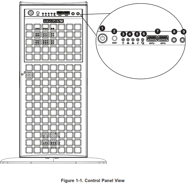
Control Panel
The switches and LEDs located on the control panel are described below. See Chapter 4 for details on the control panel connections.
| Control Panel Features | ||
| Item | Feature | Description |
| 1 | Power Button | The main power switch is used to apply or remove power from the power supply to the server. Turning off system power with this button removes the main power but maintains standby power. To perform many maintenance tasks, you must unplug the system before servicing. |
| 2 | Reset Button | The reset button is used to reboot the system. |
| 3 | HDD LED | Indicates hard drive activity on the hard drive when flashing. |
| 4 | NIC LED | Indicates network activity on the LAN when flashing. |
| 5 | Information LED | Alerts operator of several states. See the table below for details. |
| 6 | Power Fail | Indicates a power failure in the system’s power supply units. |
| 7 | USB3.2 Gen1x1 (5G) | Two USB3.2 Gen1x1 (5G). |
| 8 | Line out | Line out port. |
| 9 | Mic | Mic port. |
| Information LED | |
| Status | Description |
| Continuously on and red | An overheat condition has occurred. (This may be caused by cable congestion.) |
| Blinking red (1 Hz) | Fan failure, check for an inoperative fan. |
| Blinking red (0.25 Hz) | Power failure, check for a non-operational power supply. |
| Solid blue | Local UID has been activated. Use this function to locate the server in a rack environment. |
| Blinking blue | Remote UID is on. Use this function to identify the server from a remote location. |
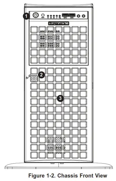
Front Features
The SC747BTS-R2K20BP is a 4U tower chassis that can also be rackmounted. See the illustration below for the features included on the front of the chassis.
| Front Chassis Features | ||
| Item | Feature | Description |
| 1 | Control Panel | Front control panel (see preceding page). |
| 2 | Bezel Lock | Locks the bezel for secure access. |
| 3 | Hot-swap Drive Bays | Eight 3.5” drive bays. |
Rear Features
The illustration below shows the features included on the rear of the chassis.
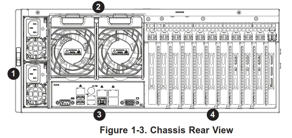
| Rear Chassis Features | ||
| Item | Feature | Description |
| 1 | Power | 1+1 2200W redundant power supply with PMBus |
| 2 | FAN | Two 8-cm PWM hot-swap rear fans |
| 3 | I/O Backpanel | Rear input/output ports (details in Chapter 4) |
| 4 | PCI-E Slots | Eleven full-height, full-length PCI-E slots |
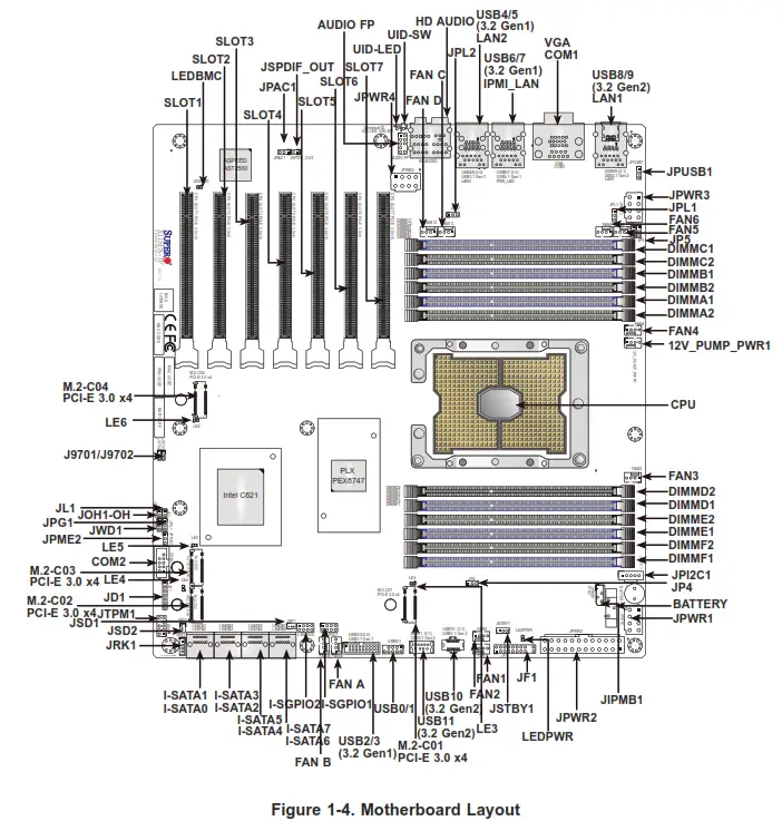
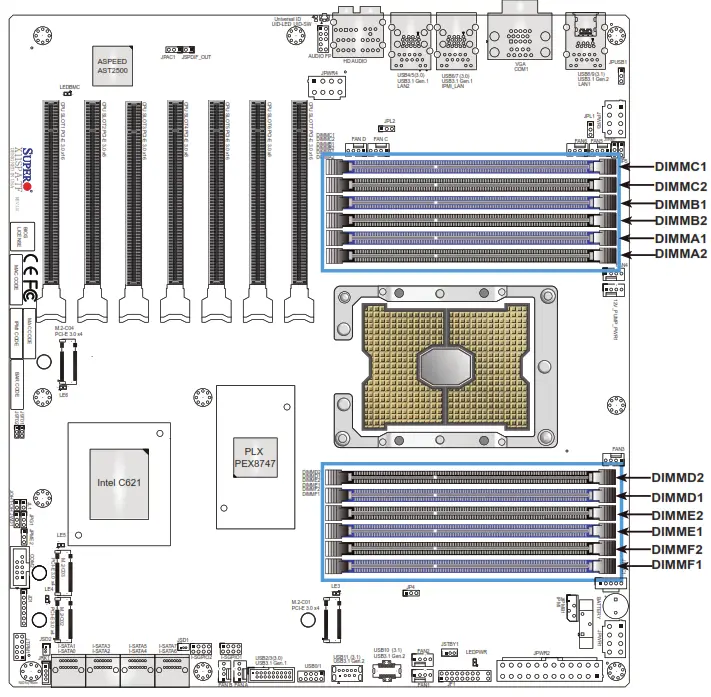
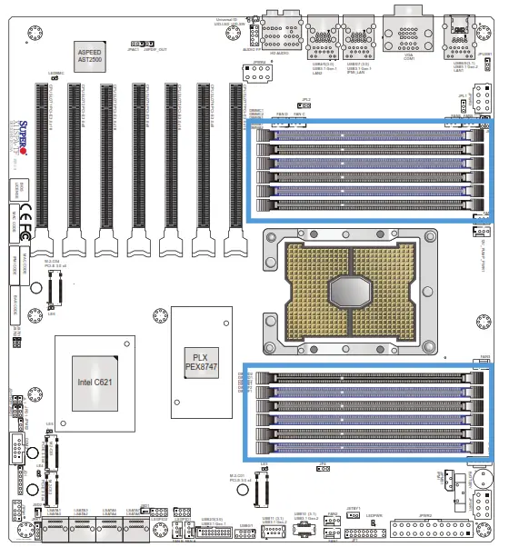
1.5 Motherboard Layout
Below is a layout of the X11SPA-T with jumper, connector, and LED locations shown. See the table on the following page for descriptions. For detailed descriptions, pinout information, and jumper settings, refer to Chapter 4.
Quick Reference Table
| Jumper | Description | Default Setting |
| J9701, J9702 | Manufacturing Mode | Pins 1-2 (Normal) |
| JPAC1 | Audio Enable/Disable | Pins 1-2 (Enabled) |
| JPG1 | VGA Enable/Disable | Pins 1-2 (Enabled) |
| JPL1, JPL2 | LAN1/LAN2 Enable/Disable | Pins 1-2 (Enabled) |
| JPME2 | Intel Manufacturing Mode | Pins 1-2 (Normal) |
| JWD1 | Watch Dog Function Enable | Pins 1-2 (Reset) |
| LED | Description | Status |
| LE3, LE4, LE5, LE6 | M.2 LED | Blinking Green: Device Working |
| LEDBMC | BMC Heartbeat LED | Blinking Green: BMC Normal |
| LEDPWR | Onboard Power LED | Solid Green: Power On |
| UID-LED | Unit Identifier (UID) LED | Blue On: Unit Identified |
| Connector | Description |
| 12V_PUMP_PWR1 | 12V 4-pin power connector for CPU liquid cooling pump |
| AUDIO FP | Front Panel Audio Header |
| BATTERY | Onboard Battery |
| COM1, COM2 | COM1: COM Port (back panel), COM2: COM Header |
| CPU SLOT1/3/5/7 PCI-E 3.0 x16 | PCI-Express x16 Slots Note: PCI-E SLOT1 will change to PCI-Express x8 link when either M.2-C03 or M.2-C04 is populated with an SSD. PCI-E SLOT1 will be completely disabled when either M.2-C01 or M.2-C02 is populated with an SSD. |
| CPU SLOT2/4/6 PCI-E 3.0 x8 (in x16) | PCI-Express x16 Slots (PCI-Express x8 link) |
| FAN1 ~ FAN6 | CPU Fan Headers |
| FAN A ~ FAN D | System Fan Headers Note: The initial system fan speed must not be lower than 600 RPM. |
| HD AUDIO | Back Panel High Definition Audio Ports |
| IPMI_LAN | Dedicated IPMI LAN Port Note: For IPMI support, X11SPA-T is via ME. |
| I-SATA0 ~ 7 | Intel Serial ATA (SATA 3.0) Ports 0~7 (6Gb/sec) |
| I-SGPIO1, I-SGPIO2 | Serial General Purpose I/O Headers |
| JD1 | Speaker/Power LED Indicator |
| JF1 | Front Control Panel Header |
| JIPMB1 | 4-pin External I2C Header (for an IPMI card) |
| JL1 | Chassis Intrusion Header |
Note: The Quick Reference table continues on the following page.
| Connector | Description |
| JOH1-OH | Overheat LED Indicator |
| JP4, JP5 | JP4: Enable/Disable USB10/11, JP5: Enable/Disable USB8/9 |
| JPI2C1 | Power Supply SMBus I2C Header |
| JPUSB1 | Enable/Disable USB6/7 WakeUp |
| JPWR1/3/4 | +12V 8-pin CPU Power Connectors (required) |
| JPWR2 | 24-pin ATX Main Power Connector (required) |
| JRK1 | Intel RAID Key Header Note: A VROC hardware key is required to enable an M.2 RAID card. |
| JSD1, JSD2 | SATA DOM (Disk-On-Module) Power Connectors |
| JSPDIF_OUT | Sony/Philips Digital Interface (S/PDIF) Out Header |
| JSTBY1 | Standby Power Header (5V) |
| JTPM1 | Trusted Platform Module (TPM) Header |
| LAN1, LAN2 | RJ45 1GbE/10GbE LAN Ports |
| PCI-E M.2-C01/C02/C03/C04 PCI-E 3.0 x4 | PCI-E M.2 Connectors (small form factor devices and other portable devices for high speed NVMe SSDs) |
| UID-SW | Unit Identifier (UID) Switch |
| USB0/1 | Front Access USB 2.0 Header |
| USB2/3 | Front Access USB 3.2 Gen1 Header |
| USB4/5, USB6/7 | Back Panel USB 3.2 Gen1 Ports Note: X11SPA-T does not support S3 or S4. Note: Either USB4/5 or USB6/7 will support standby power. |
| USB8/9 | Back Panel USB3.2 Gen2x1 Ports |
| USB10/11 | Front Access USB3.2 Gen2x1 Headers (USB10: Type A, USB11: Type C) |
| VGA | VGA Port |
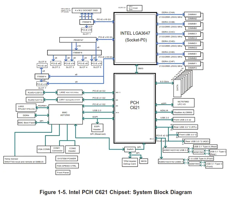
Note: This is a general block diagram and may not exactly represent the features on your motherboard. See the System Specifications appendix for the actual specifications of your motherboard.
Chapter 2 Installation
2.1 Overview
This chapter provides advice and instructions for rack or workstation installation. The system is shipped in a workstation configuration. Follow the steps in this chapter to prepare the chassis for rack mounting or for returning the chassis into a workstation configuration.
If your system is not already fully integrated with processors, system memory, etc., refer to Chapter 3 for details on installing those specific components.
Caution: Electrostatic Discharge (ESD) can damage electronic components. To prevent such damage to PCBs (printed circuit boards), it is important to use a grounded wrist strap, handle all PCBs by their edges and keep them in anti-static bags when not in use.
2.2 Preparing for Rack or Workstation Setup
Please read this section in its entirety before you begin the installation. Whether you are operating the system in a rack environment or as a workstation, follow a few general precautions.
General Precautions
- Review the electrical and general safety precautions in Appendix B.
- Use a regulating uninterruptible power supply (UPS) to protect the system from power surges and voltage spikes and to keep your system operating in case of a power failure.
- Allow any drives and power supply modules to cool before touching them.
- To maintain proper cooling, always keep all chassis panels closed and all SATA carriers installed when not being serviced.
Choosing a Setup Location
- The system should be situated in a clean, dust-free area that is well-ventilated. Avoid areas where heat, electrical noise, and electromagnetic fields are generated.
- Leave enough clearance in front of the rack so that you can open the front door completely (~25 inches) and approximately 30 inches of clearance in the back of the rack to allow sufficient space for airflow and access when servicing.
- This product should be installed only in a Restricted Access Location (dedicated equipment rooms, service closets, etc.).
- This product is not suitable for use with visual display workplace devices according to §2 of the German Ordinance for Work with Visual Display Units.
Workstation Precaution
Ensure that the caster wheels on the workstation are locked.
- Rack Precautions
- Ensure that the leveling jacks on the bottom of the rack are extended to the floor so that the full weight of the rack rests on them.
- In single rack installations, stabilizers should be attached to the rack. In multiple rack installations, the racks should be coupled together.
- Always make sure the rack is stable before extending a server or other component from the rack.
- You should extend only one server or component at a time – extending two or more simultaneously may cause the rack to become unstable.
Rack Mounting Considerations
Ambient Operating Temperature
If installed in a closed or multi-unit rack assembly, the ambient operating temperature of the rack environment may be greater than the room’s ambient temperature. Therefore,
consideration should be given to installing the equipment in an environment compatible with the manufacturer’s maximum rated ambient temperature (TMRA).
Airflow
Equipment should be mounted into a rack so that the amount of airflow required for safe operation is not compromised.
Mechanical Loading
Equipment should be mounted into a rack so that a hazardous condition does not arise due to uneven mechanical loading.
Circuit Overloading
Consideration should be given to the connection of the equipment to the power supply circuitry and the effect that any possible overloading of circuits might have on overcurrent protection and power supply wiring. Appropriate consideration of equipment nameplate ratings should be used when addressing this concern.
Reliable Ground
A reliable ground must be maintained at all times. To ensure this, the rack itself should be grounded. Particular attention should be given to power supply connections other than the direct connections to the branch circuit (i.e. the use of power strips, etc.).
![]() To prevent bodily injury when mounting or servicing this unit in a rack, you must take special precautions to ensure that the system remains stable. The following guidelines are provided to ensure your safety:
To prevent bodily injury when mounting or servicing this unit in a rack, you must take special precautions to ensure that the system remains stable. The following guidelines are provided to ensure your safety:
- This unit should be mounted at the bottom of the rack if it is the only unit in the rack.
- When mounting this unit in a partially filled rack, load the rack from the bottom to the top with the heaviest component at the bottom of the rack.
- If the rack is provided with stabilizing devices, install the stabilizers before mounting or servicing the unit in the rack.
![]() Slide rail mounted equipment is not to be used as a shelf or a work space.
Slide rail mounted equipment is not to be used as a shelf or a work space.![]() Warning: Do not pick up the server with the front handles. They are designed to pull the system from a rack only.
Warning: Do not pick up the server with the front handles. They are designed to pull the system from a rack only.
2.3 Preparing the Chassis for Rack Mounting
The chassis top tower cover and feet must be removed before rack installation.
Removing the Top Tower Cover
- Locate the blue cover lock at the rear of the cover.
- Slide the lock to the right and push the cover forward.
- Lift the top cover off the chassis.
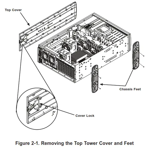
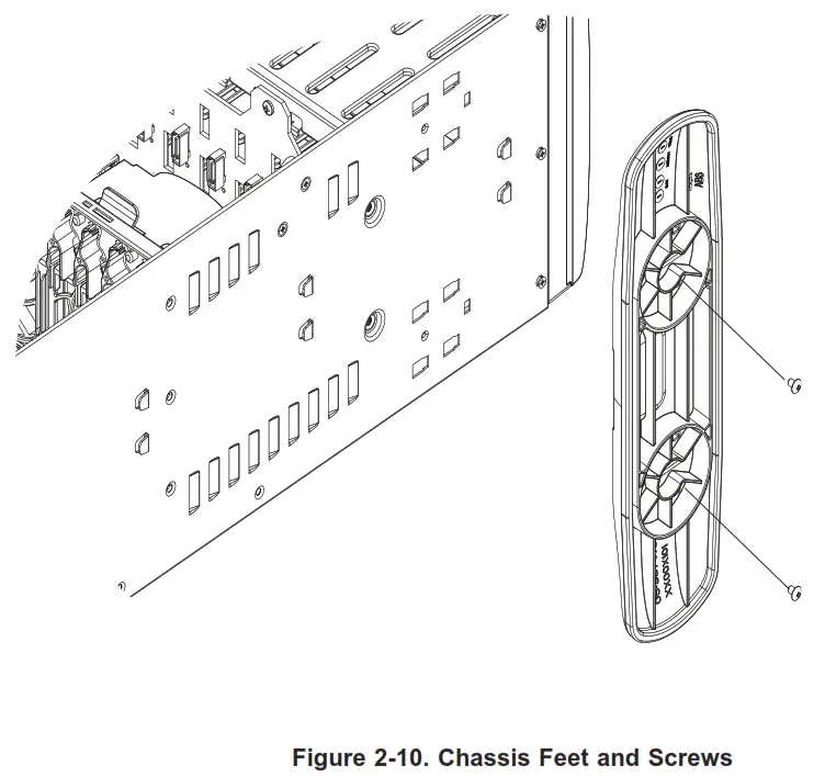
Removing the Chassis Feet
- Lay the chassis on its side.
- Remove the screws holding the chassis feet in place.
- Each foot has a foot lock tab at the center. Use a flat-head screwdriver to gently lift the foot lock upward. Slide the foot toward the rear of the chassis.
2.4 Installing the Rails
This section provides a guideline for installing the rails to the chassis and to the rack with the optional rack mount kit.
Identifying the Sections of the Rack Rails
The chassis package includes two optional rack rail assemblies in the rack mounting kit. Each assembly consists of two sections: An inner fixed chassis rail that secures directly to the server chassis and an outer fixed rack rail that secures directly to the rack itself.

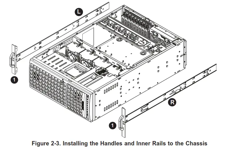
Installing the Inner Rails to the Chassis
- Attach the handles to the front of the chassis with three screws each.
- Identify the left and right inner rails. They are labeled on the rails and in the figure below.
- Align each rail with the screw holes along the side of the chassis.
- Screw the rails securely to the side of the chassis.
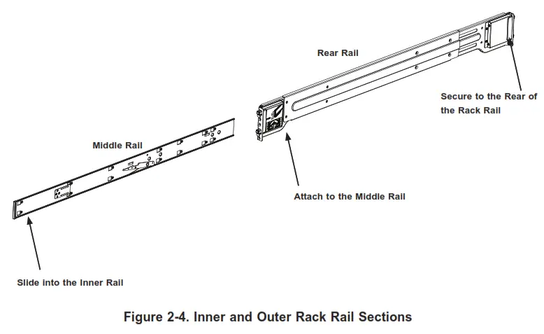
Installing the Outer Rails to the Rack
Installing the Outer Rails
- Attach the rear rail to the middle rail.
- Adjust both to the proper distance so that the rails fit snugly into the rack.
- Secure the rear rail with two M5 screws at the rear of the rack.
- Repeat steps 1-3 for the left outer rail.
2.5 Installing the Chassis into the Rack
With rails attached to both the chassis and the rack, install the system into the rack.
- Confirm that the chassis includes the inner rails and the outer rails.
- Align the inner chassis rails with the front of the outer rack rails.
- Slide the inner rails into the outer rails, keeping the pressure even on both sides (you may have to depress the locking tabs when inserting). When the chassis has been pushed completely into the rack, you should hear the locking tabs “click” into the locked position.
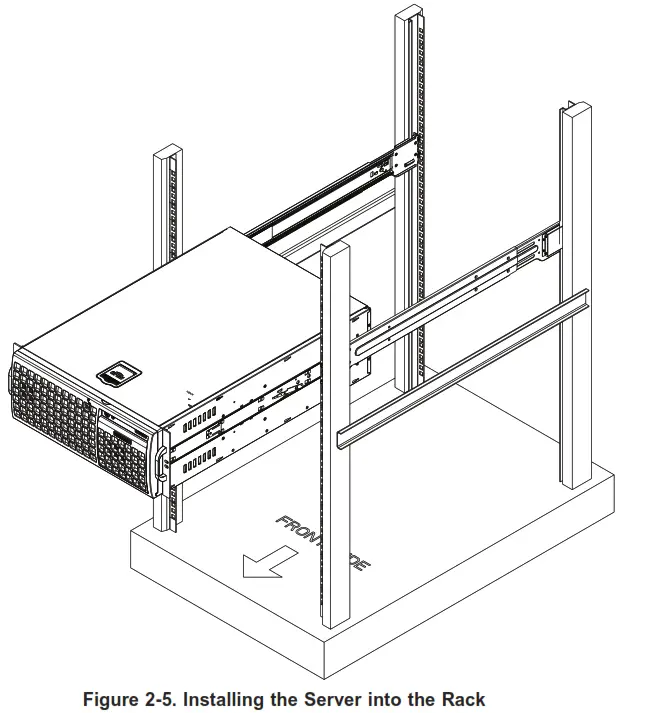
Note: The figure is for illustrative purposes only. Always install servers to the bottom of a rack first.![]() Warning: Stability hazard. The rack stabilizing mechanism must be in place, or the rack must be bolted to the floor before you slide the unit out for servicing. Failure to stabilize the rack can cause the rack to tip over.
Warning: Stability hazard. The rack stabilizing mechanism must be in place, or the rack must be bolted to the floor before you slide the unit out for servicing. Failure to stabilize the rack can cause the rack to tip over.![]() When initially installing the system to a rack, test that the rail locking tabs engage to prevent the system from being overextended. Have a rack lift in place as a precaution in case the test fails.
When initially installing the system to a rack, test that the rail locking tabs engage to prevent the system from being overextended. Have a rack lift in place as a precaution in case the test fails.
Removing the Chassis from the Rack
Caution! It is dangerous for a single person to offload the heavy chassis from the rack without assistance. Be sure to have sufficient assistance supporting the chassis when removing it from the rack. Use a lift.
- Remove the screws that hold the front of the server to the rack.
- Pull the chassis forward out the front of the rack until it stops.
- Find the quick-release tab on each side of the chassis on the inner rails. Press down on the quick-release tab and continue to pull the chassis out of the rack.
![]() Warning: In any instance of pulling the system from the rack, always use a rack lift and follow all associated safety precautions.
Warning: In any instance of pulling the system from the rack, always use a rack lift and follow all associated safety precautions.![]() Slide rail mounted equipment is not to be used as a shelf or a work space.
Slide rail mounted equipment is not to be used as a shelf or a work space.
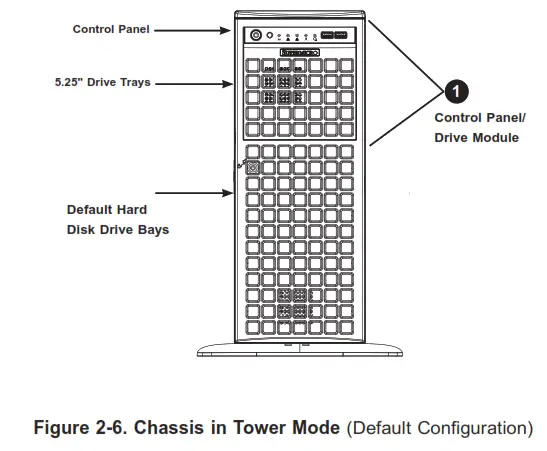
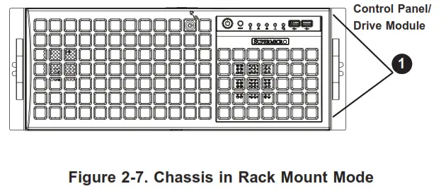
2.6 Control Panel Orientation
The server can be configured for either tower or server rack orientation. It is shipped in tower mode and can be immediately used as a desktop server. To use it in a rack, rotate the module that contains the control panel and the three drive trays ( 1 in Figure 2-7) 90 degrees.
Note that two of the 5.25″ drives may be replaced by a mobile rack containing eight 2.5″ storage drives.
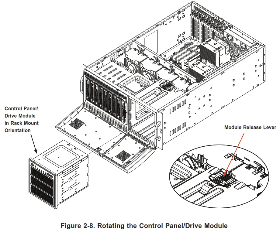
Rotating the Control Panel/Drive Module for Rack Mounting
- Power down the system as described in Section 3.1 and open the side cover as described in Section 3.2.
- Disconnect any cables from the back of the Control Panel/Drive Module.
- Push the module release lever to unlock the module.

- Grasp the edges of the module and pull it from the chassis.
- Rotate the module 90 degrees so that the control panel is on top.
- Reinsert the module into the chassis and reconnect the cables.
Caution: Use caution when working around the backplane. Do not touch the module backplane with any metal objects and make sure no ribbon cables touch the backplane or
obstruct the holes, which aid in proper airflow.
2.7 Workstation Setup
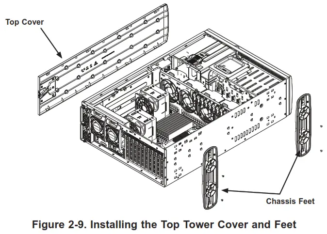
The system can be configured in a workstation or a server rack orientation. It is shipped as a workstation with the chassis cover and feet pre-installed. Use the instructions below to convert a rack-mounted system to tower mode.
Returning a Rackmounted System to a Workstation Setup
- Shut down the system and remove power as described in Section 3.1.
- Remove the chassis from the rack as described in Section 2.5.
- Remove the inner rails and the handles.
- Align the cover post with the corresponding holes on the top of the chassis and place the cover on top of the chassis.
- Slide the cover toward the rear of the chassis to lock the cover into place.

- Place the chassis foot in the foot receptacle and slide the foot toward the front of the chassis. The foot should lock into place.
- Secure the foot to the chassis using two screws enclosed in the packaging.
- Repeat steps 6 and 7 for the other chassis foot.
- Rotate the control panel for a workstation orientation following the steps in Section 2.6.

Chapter 3 Maintenance and Component Installation
This chapter provides instructions on installing and replacing main system components. To prevent compatibility issues, only use components that match the specifications and/or part numbers given. Installation or replacement of most components requires that power first be removed from the system. Please follow the procedures given in each section.
3.1 Removing Power
Use the following procedure to ensure that power has been removed from the system. Use the operating system to power down the system.
- After the system has completely shut down, disconnect the AC power cords from the power strip or outlet.
- Disconnect the power cords from the power supply modules.
3.2 Accessing the System
The SC747BTS-R2K20BP chassis features a removable top cover, side cover, and front cover allowing access to the interior.
See Section 2.3 for instructions to remove the top cover.
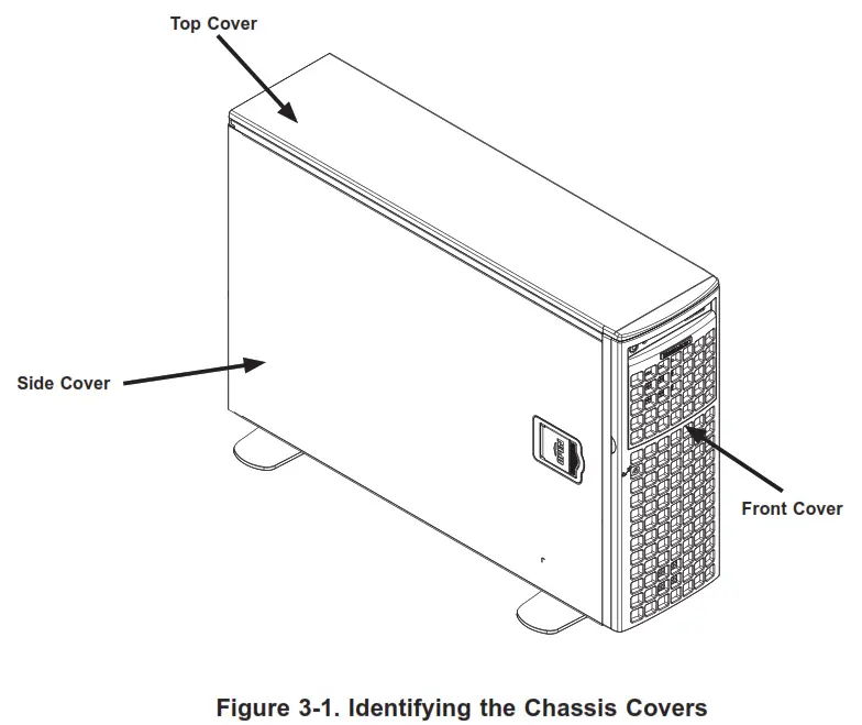
Caution: Except for short periods of time, do not operate the server without the cover in place. The chassis cover must be in place to allow for proper airflow and to prevent overheating.
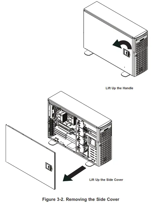
Removing the Side Cover
- Remove power from the system as described in Section 3.1.
- Lift the handle at the side of the tower.
- Lift the cover from the chassis.
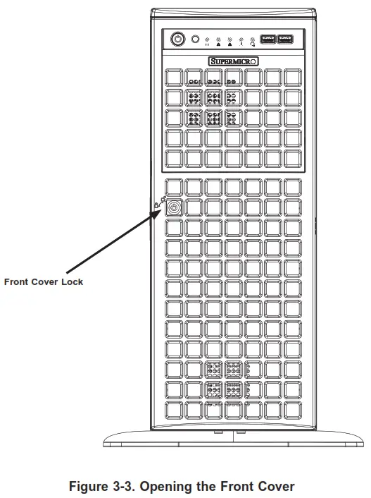
Opening the Front Cover
The front cover houses up to eight hot-swappable hard drives. The cover can be locked to prevent unauthorized access. The key to this lock is shipped with the system.
- Unlock the front cover using the key shipped with the system.
- Gently pull the cover open.
3.3 Motherboard Components
Processor and Heatsink Installation
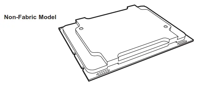
Intel® Xeon® Scalable Processors come in two models: Fabric (F model) and Non-Fabric (Non-F model). Only the Non-Fabric model is supported for this system. The processor (CPU) and heatsink should be assembled together first to form the processor heatsink module (PHM), and then install the PHM into the CPU socket. Caution: Use ESD protection. Do not touch the underside of the CPU. Improper installation or socket misalignment can cause serious damage to the CPU or socket which may require manufacturer repairs.
Notes:
- All power should be off, as described in Section 3.1, before installing the processors.
- When handling the processor package, avoid placing direct pressure on the label area of the CPU or socket.
- Check that the plastic socket dust cover is in place and none of the socket pins are bent—otherwise, contact your retailer.
- Refer to the Supermicro website for updates on CPU support.
- Graphics in this manual are for illustration. Your components may look slightly different.
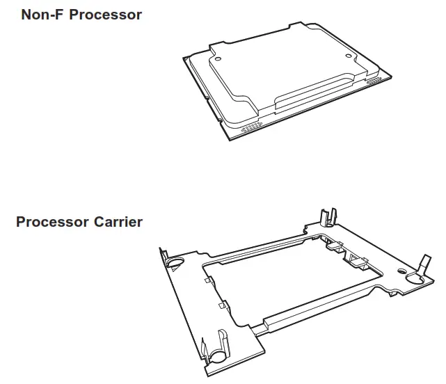
The Intel Xeon SP Series Processor
Overview of the Processor Carrier Assembly
The processor carrier assembly contains the Intel Xeon Non-Fabric (Non-F) processor and a processor carrier.
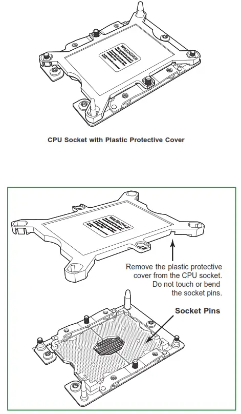
Overview of the CPU Socket
The CPU socket is protected by a plastic protective cover.
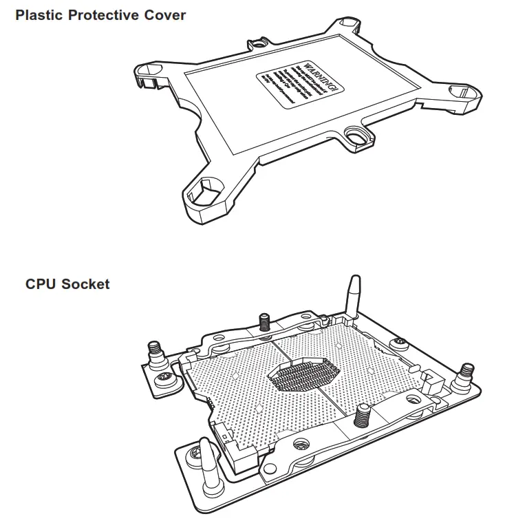
Note: Be sure to cover the CPU socket with the dust cover when the CPU is not installed.
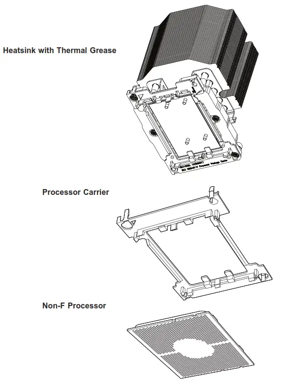
Overview of the Processor Heatsink Module
The Processor Heatsink Module (PHM) contains a heatsink, a processor carrier, and the Intel Xeon Non-Fabric (Non-F) processor.
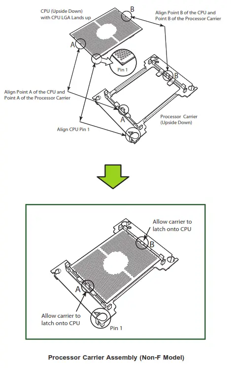
Creating the Non-F Model Processor Carrier Assembly
To install a Non-F model processor into the processor carrier, follow the steps below.
- Hold the processor with the LGA lands (gold contacts) facing up. Locate the small, gold triangle in the corner of the processor and the corresponding hollowed triangle on the processor carrier. These triangles indicate pin 1. See the images below.
- Using the triangles as a guide, carefully align and place Point A of the processor into Point A of the carrier. Then gently flex the other side of the carrier for the processor to fit into Point B.
- Examine all corners to ensure that the processor is firmly attached to the carrier.
Attaching the Non-F Model Processor Package Assembly to the Heatsink to Form the Processor Heatsink Module (PHM)
After you have made a processor package assembly by following the instructions on the previous page, please follow the steps below to mount the processor package assembly onto the heatsink to create the Processor Heatsink Module (PHM).
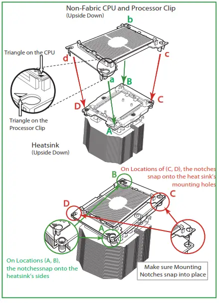
- Locate “CPU 1” on the heatsink label and the triangular corner next to it on the heatsink. With your index finger pressing against the screw at this triangular corner, carefully hold and turn the heatsink upside down with the thermal-grease side facing up. Remove the protective thermal film if present, and apply the proper amount of the thermal grease as needed. (Skip this step if you have a new heatsink because the necessary thermal grease is pre-applied in the factory.)
- Holding the processor package assembly at the center edge, turn it upside down. With the thermal-grease side facing up, locate the hollow triangle located at the corner of the processor carrier assembly (“a” in the graphic). Note a larger hole and plastic mounting clicks are located next to the hollow triangle. Also, locate another set of mounting clicks and a larger hole at the diagonal corner of the same (reverse) side of the processor carrier assembly (“b” in the graphic).
- With the back of the heatsink and the reverse side of the processor package assembly facing up, align the triangular corner on the heatsink(“A” in the graphic) against the
mounting clips next to the hollow triangle (“a”) on the processor package assembly. - Also align the triangular corner (“B”) at the diagonal side of the heatsink with the corresponding clips on the processor package assembly (“b”).
- Once the mounting clips on the processor package assembly are properly aligned with the corresponding holes on the back of a heatsink, securely attach the heatsink to the processor package assembly by snapping the mountingclips at the proper places on the heatsink to create the processor heatsink module (PHM).

Preparing the CPU Socket for Installation
This motherboard comes with a plastic protective cover installed on the CPU socket. Remove it from the socket to install the Processor Heatsink Module (PHM). Gently pull up one corner of the plastic protective cover to remove it.
Installing the Processor Heatsink Module (PHM)
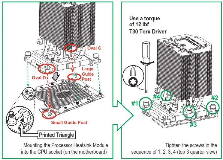
- Once you have assembled the processor heatsink module (PHM) by following the instructions listed on page 42, you are ready to install the processor heatsink module (PHM) into the CPU socket on the motherboard. To install the PHM into the CPU socket, follow the instructions below.
- Locate the triangle (pin 1) on the CPU socket, and locate the triangle (pin 1) at the corner of the PHM that is closest to “1.” (If you have difficulty locating pin 1 of the PHM, turn the PHM upside down. With the LGA-lands side facing up, you will note the hollow triangle located next to a screw at the corner. Turn the PHM right side up, and you will see a triangle marked on the processor clip at the same corner of hollow triangle.)
- Carefully align pin 1 (the triangle) on the PHM against pin 1 (the triangle) on the CPU socket.
- Once they are properly aligned, insert the two diagonal oval holes on the heatsink into the guiding posts.
- Using a T30 Torx-bit screwdriver, install four screws into the mounting holes on the socket to securely attach the PHM onto the motherboard starting with the screw marked “1” (in the sequence of 1, 2, 3, and 4).
Note: Do not use excessive force when tightening the screws to avoid damaging the
LGA-lands and the processor.
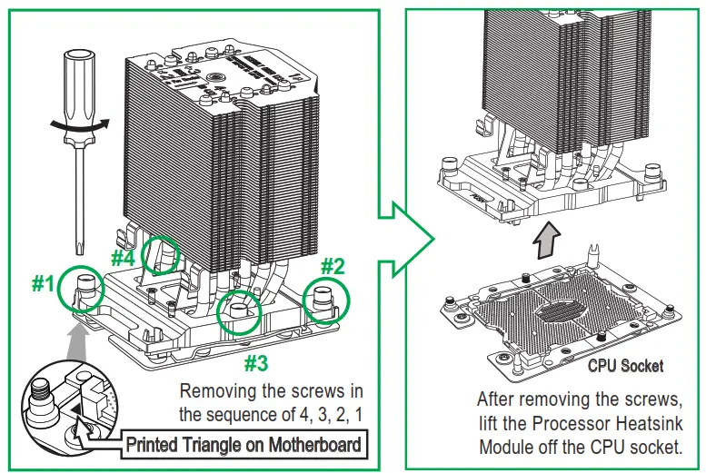
Removing the Processor Heatsink Module (PHM) from the Motherboard
Before removing the processor heatsink module (PHM), unplug the power cord from the power outlet.
- Using a T30 Torx-bit screwdriver, turn the screws on the PHM counterclockwise to loosen them from the socket, starting with the screw marked #4 (in the sequence of 4,
3, 2, 1). - After all four screws are removed, wiggle the PHM gently and pull it up to remove it from the socket.
Note: To properly remove the processor heatsink module, be sure to loosen and remove the screws on the PHM in the sequence of 4, 3, 2, and 1 as shown below.
3.4 Memory Support and Installation
The X11SPA-T supports up to 768GB of ECC RDIMM, 3TB of 3DS RDIMM, 1.5TB of LRDIMM, and 3TB of 3DS LRDIMM DDR4 (288-pin) ECC memory with speeds of up to 2933MHz in 12 memory slots. Refer to the tables below for the recommended DIMM population order and additional memory information. (1DPC and 2DPC are recommended for memory installation.) Note: 2933MHz memory is supported by 2 nd Generation Intel Xeon Scalable-SP (82XX/62XX series) and W-32XX series processors.
Memory Installation Sequence
Memory modules for this motherboard are populated using the “Fill First” method. The blue memory slot of each channel is considered the first DIMM module of the channel, and the black slot is considered the second module of the channel. When installing memory modules, be sure to populate the blue memory slots first, and then the black slots. To maximize memory capacity and performance, please populate all DIMM slots on the motherboard, including all blue and black slots.
General Memory Population Requirements
- Be sure to use memory modules of the same type and speed on the motherboard. Mixing of memory modules of different types and speeds is not allowed.
- Using unbalanced memory topology such as populating two DIMMs in one channel while populating one DIMM in another channel on the same motherboard will result in reduced memory performance.
- Populating memory slots with a pair of DIMM modules of the same type and size will result in interleaved memory, which will improve memory performance.
DDR4 Memory Support for the 81xx/61xx/51xx/41xx/31xx Platform
| DDR4 Memory Support | ||||||
| Type | Ranks Per DIMM & Data Width | DIMM Capacity (GB) | Speed (MT/s); Voltage On; Slots Per Channel (SPC) and DIMMs Per Channel (DPC) | |||
| 1 Slot Per Channel | 2 Slots Per Channel | |||||
| DRAM Density | 1DPC (1-DIMM Per Channel) | 1DPC (1- DIMM Pernel) Chan | 2DPC (2-DIMM Per Channel) | |||
| 4Gb* | 8Gb | 1.2 V | 1.2 V | 1.2 V | ||
| RDIMM RDIMM RDIMM RDIMM RDIMM 3Ds RDIMM 3Ds LRDIMM | SRx4 SRx8 DRx8 DRx4 QRX4 8RX4 QRx4 | 4GB 8GB 8GB 16GB N/A N/A 32GB | 8GB 16GB 16GB 32GB 2H-64GB 4H-128GB 64GB | 2666 2666 2666 2666 2666 2666 2666 | 2666 2666 2666 2666 2666 2666 2666 | 2666 2666 2666 2666 2666 2666 2666 |
| LRDIMM 3Ds LRDIMM 3Ds | QRX4 8Rx4 | N/A N/A | 2H-64GB 4H-128GB | 2666 2666 | 2666 2666 | 2666 2666 |
DDR4 Memory Support for the 82xx/62xx/52xx/42xx/32xx and W-32XX Platforms
| DDR4 Memory Support | |||||||
| Type RDIMM RDIMM RDIMM RDIMM RDIMM 3Ds RDIMM 3Ds LRDIMM | Ranks Per DIMM & Data Width SRx4 SRx8 DRx8 DRx4 QRX4 8RX4 QRx4 | DIMM Capacity (GB) | Speed (MT/s); Voltage (V); Slots Per Channel (SPC) and DIMMs Per Channel (DPC) | ||||
| 1 Slot Per Channel | 2 Slots Per Channel | ||||||
| DRAM Density | 1DPC (1-DIMM Per Channel) | 1DPC (1-DIMM Per Channel) | 2DPC (2-DIMM Per Channel) | ||||
| 4Gb* 4GB 8GB 8GB 16GB N/A N/A 32GB | 8Gb 8GB 16GB 16GB 32GB 2H-64GB 4H-128GB 64GB | 16Gb 16GB 32GB 32GB 64GB 21-1-128GB 41-1-256GB 128GB | 1.2 V 2933 2933 2933 2933 2933 2933 2933 | 1.2 V 2933 2933 2933 2933 2933 2933 2933 | 1.2 V 2933 2933 2933 2933 2933 2933 2933 | ||
| LRDIMM 3Ds LRDIMM 3Ds | QRX4 8Rx4 | N/A N/A | 2H-64GB 4H-128GB | 21-1-128GB 41-1-256GB | 2933 2933 | 2933 2933 | 2933 2933 |
DIMM Population Guidelines for Optimal Performance
For optimal memory performance, follow the instructions listed in the tables below when populating memory modules.
Key Parameters for DIMM Configuration
| Key Parameters for DIMM Configurations | |
| Parameters | Possible Values |
| Number of Channels | 1, 2, 3, 4, 5, or 6 |
| Number of DIMMs per Channel | 1DPC (1 DIMM Per Channel) or 2DPC (2 DIMMs Per Channel) |
| DIMM Type | RDIMM (w/ECC), 3DS RDIMM, LRDIMM, 3DS LRDIMM |
| DIMM Construction | Non-3DS RDIMM Raw Cards: A/B (2Rx4), C (1Rx4), D (1Rx8), E (2Rx8) 3DS RDIMM Raw Cards: A/B (4Rx4) Non-3DS LRDIMM Raw Cards: D/E (4Rx4) 3DS LRDIMM Raw Cards: A/B (8Rx4) |
DIMM Mixing Guidelines
General DIMM Mixing Guidelines
DIMM Mixing Rules
- All DIMMs must be DDR4 DIMMs.
- x4 and x8 DIMMs can be mixed in the same channel.
- Mixing of LRDIMMs and RDIMMs is not allowed in the same channel, across different channels, or across different sockets.
- Mixing of non-3DS and 3DS LRDIMM is not allowed in the same channel, across different channels, or across different sockets.
| Mixing of DIMM Types within a Channel | |||
| DIMM Types | RDIMM | LRDIMM | 3DS LRDIMM |
| RDIMM | Allowed | Not Allowed | Not Allowed |
| LRDIMM | Not Allowed | Allowed | Not Allowed |
| 3DS LRDIMM | Not Allowed | Not Allowed | Allowed |
Memory Population
Memory Population Table for the X11SPA-T (with 12 Slots) based on the 81xx/61xx/51xx/41xx/31xx and
82xx/62xx/52xx/42xx/32xx and W-32XX series Platforms.
| Memory Population Table for the X11SPA-T (with 12 Slots) | |
| 1 CPU & 1 DIMM 1 CPU & 2 DIMMs 1 CPU & 3 DIMMs 1 CPU & 4 DIMMs 1 CPU & 5 DIMMs (Unbalanced: not recommended) 1 CPU & 6 DIMM 1 CPU & 7 DIMMs (Unbalanced: not recommended) 1 CPU & 8 DIMMs 1 CPU & 9 DIMMs (Unbalanced: not recommended) 1 CPU & 10 DIMMs (Unbalanced: not recommended) 1 CPU & 11 DIMMs (Unbalanced: not recommended) 1 CPU & 12 DIMMs | Memory Population Sequence CPU1: P1-DIMMA1 CPU1: P1-DIMMA1/P1-DIMMD1 CPU1: P1-DIMMC1/P1-DIMMB1/P1-DIMMA1 CPU1: P1-DIMMB1/P1-DIMMA1/P1-DIMMD1/P1-DIMME1 CPU1: P1-DIMMC1/P1-DIMMB1/P1-DIMMA1/P1-DIMMD1/P1-DIMME1 CPU1: P1-DIMMC1/P1-DIMMB1/P1-DIMMA1/P1-DIMMD1/P1-DIMME1/P1-DIMMF1 CPU1: P1-DIMMB1/P1-DIMMB2/P1-DIMMA1/P1-DIMMA2/P1-DIMMD1/P1-DIMME1/ P1-DIMMF1 CPU1: P1-DIMMB1/P1-DIMMB2/P1-DIMMA1/P1-DIMMA2/P1-DIMMD2/P1-DIMMD1/ P1-DIMME2/P1-DIMME1 CPU1: P1-DIMMC1/P1-DIMMC2/P1-DIMMB1/P1-DIMMB2/P1-DIMMA1/P1-DIMMA2/ P1-DIMMD1/P1-DIMME1/P1-DIMMF1 CPU1: P1-DIMMC1/P1-DIMMB1/P1-DIMMB2/P1-DIMMA1/P1-DIMMA2/ P1-DIMMD2/P1-DIMMD1/P1-DIMME2/P1-DIMME1/P1-DIMMF1 CPU1: P1-DIMMC1/P1-DIMMC2/P1-DIMMB1/P1-DIMMB2/P1-DIMMA1/P1-DIMMA2/ P1-DIMMD2/P1-DIMMD1/P1-DIMME2/P1-DIMME1/P1-DIMMF1 CPU1: P1-DIMMC1/P1-DIMMC2/P1-DIMMB1/P1-DIMMB2/P1-DIMMA1/P1-DIMMA2/ P1-DIMMD2/P1-DIMMD1/P1-DIMME2/P1-DIMME1/P1-DIMMF2/P1-DIMMF1 |
Note: Unbalanced memory configuration decreases memory performance and is not recommended for the Supermicro motherboards.
General Guidelines for Optimizing Memory Performance
- The blue slots must be populated first.
- Only populate DIMMA2 and DIMMD2 if extra memory support is needed.
- Always use DDR4 memory of the same type, size, and speed.
- Mixed DIMM speeds can be installed. However, all DIMMs will run at the speed of the slowest DIMM.
- The motherboard will support odd-numbered modules (one or three modules installed). However, to achieve the best memory performance, a balanced memory population is recommended.
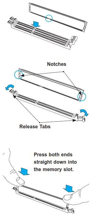
DIMM Installation
- Insert the desired number of DIMMs into the memory slots based on the recommended DIMM population on pages 47, 48, 49, and 50.
- Push the release tabs outwards on both ends of the DIMM slot to unlock it.
- Align the key of the DIMM module with the receptive point on the memory slot.
- Align the notches on both ends of the module against the receptive points on the ends of the slot.
- Press both ends of the module straight down into the slot until the module snaps into place.
- Press the release tabs to the lock positions to secure the DIMM module into the slot.
DIMM Removal
Press both release tabs on the ends of the DIMM module to unlock it. Once the DIMM module is loosened, remove it from the memory slot.
Motherboard Battery
The motherboard uses non-volatile memory to retain system information when system power is removed. This memory is powered by a lithium battery residing on the motherboard. Replacing the Battery
- Remove power from the system as described in Section 3.1 and remove the node from the chassis.
- Push aside the small clamp that covers the edge of the battery. When the battery is released, lift it out of the holder.
- To insert a new battery, slide one edge under the lip of the holder with the positive (+) side facing up. Then push the other side down until the clamp snaps over it.
Note: Handle used batteries carefully. Do not damage the battery in any way; a damaged battery may release hazardous materials into the environment. Do not discard a used battery in the garbage or a public landfill. Please comply with the regulations set up by your local hazardous waste management agency to dispose of your used battery properly.
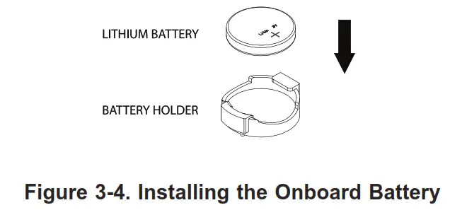
Warning: There is a danger of explosion if the onboard battery is installed upside down (which reverses its polarities). This battery must be replaced only with the same or an equivalent type recommended by the manufacturer (CR2032).
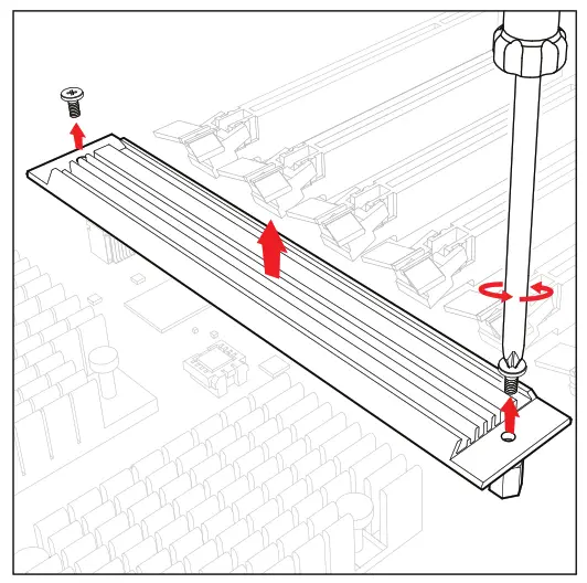
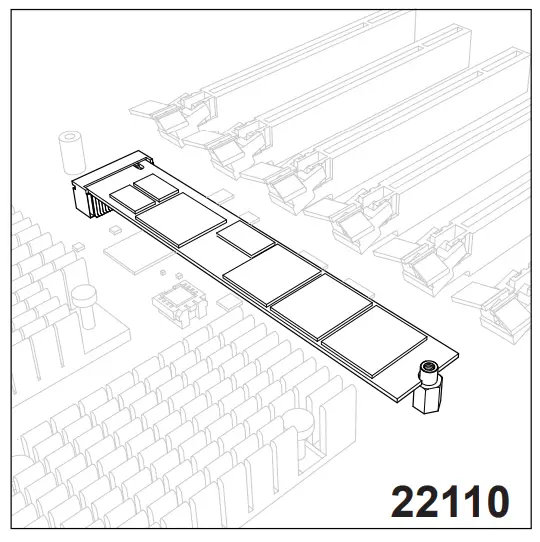
3.5 M.2 SSD Installation
The X11SPA-T motherboard has four M.2 PCI-E 3.0 slots that support 2260, 2280, and 22110 SSD modules.
- Loosen the screws and remove the heatsink.

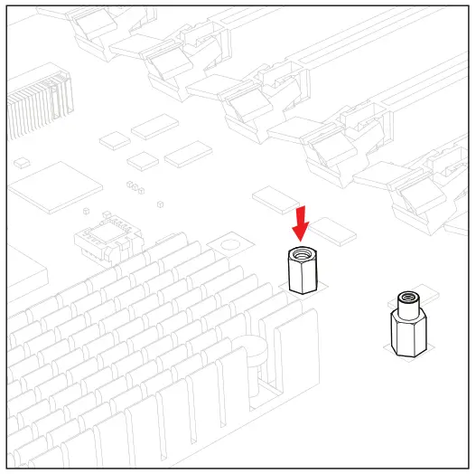
- The default positions for the standoffs are in the 2280 and 22110 mounting holes.

- The mounting screws on the bottom of the motherboard secure the standoffs.
 2280 SSD Module Installation
 - 1. To install a 2280 SSD module, insert it into the slot at a 30-degree angle and press down.
 4.2. With the cutoff circle at the end of the module aligned with the standoff, tighten the screw to secure the module. Go to step 5 to complete the installation.
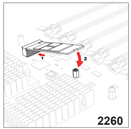
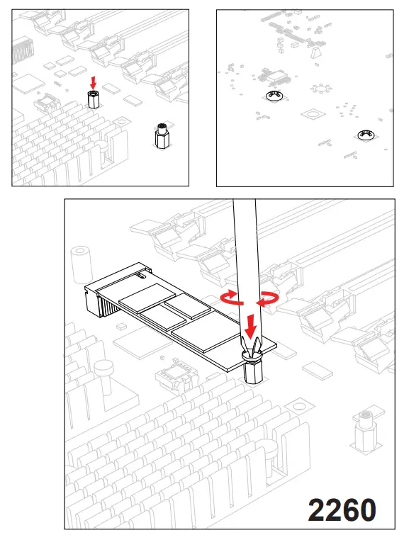
2260 SSD Module Installation
4.3. To prepare for a 2260 SSD module installation, begin by repeating steps 1-3. Then, place the standoff and screw underneath the motherboard in the hole closest to the M.2 slot. To install the module, insert it into the slot at a 30 degree angle and press down.
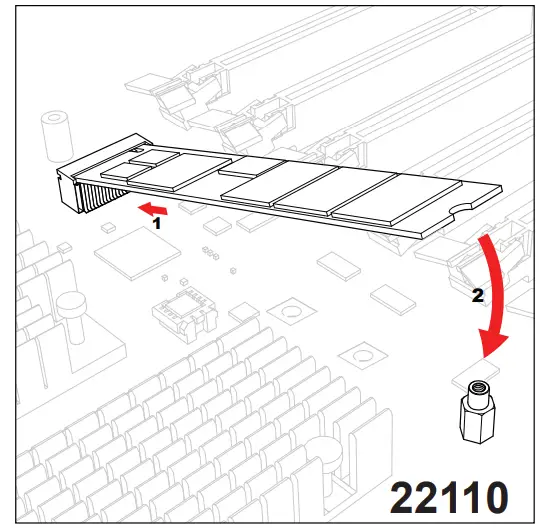
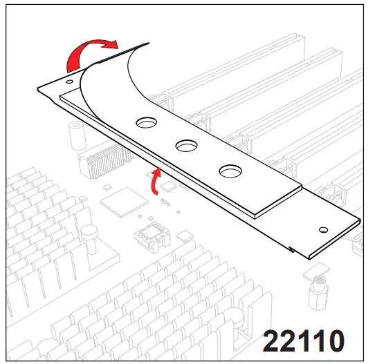
22110 SSD Module Installation
4.5. To install a 22110 SSD module, insert it into the M.2 slot at a 30 degree angle and align the cutoff circle at the end with the standoff.
4.6. Go to step 5 to complete the installation.
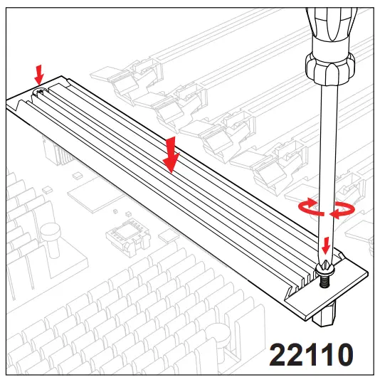
- Remove the plastic liner from the heatsink’s thermal pad.

- With the thermal pad faced down, secure the heatsink on top of the module with the same screws removed in step 1.

 2280 SSD Module Installation
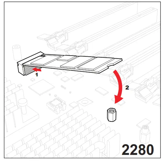 4.2. With the cutoff circle at the end of the module aligned with the standoff, tighten the screw to secure the module. Go to step 5 to complete the installation.
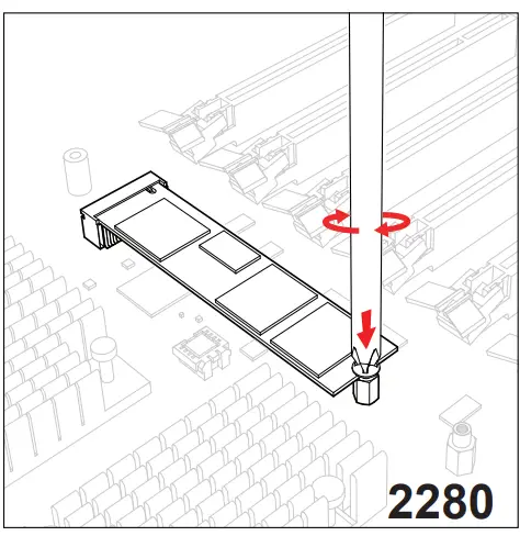
3.6 Chassis Components
Hard Drives
A total of eight SATA drives may be housed in the SC747BTS-R2K20BP chassis. The drive IDs are preconfigured as 0 through 7 in order from bottom to top (or from left to right if rackmounted).
The drives are mounted in drive carriers to simplify their installation and removal from the chassis. (Both procedures may be done without removing power from the system.)
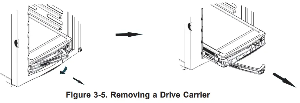
Removing a Hot-Swap Drive Carrier
- Open the front bezel then push the release button located beside the drive LEDs.
- Swing the handle fully out and then use it to pull the unit straight out.
Note: Your operating system must have RAID support to enable the hot-swap capability of the SATA drives.
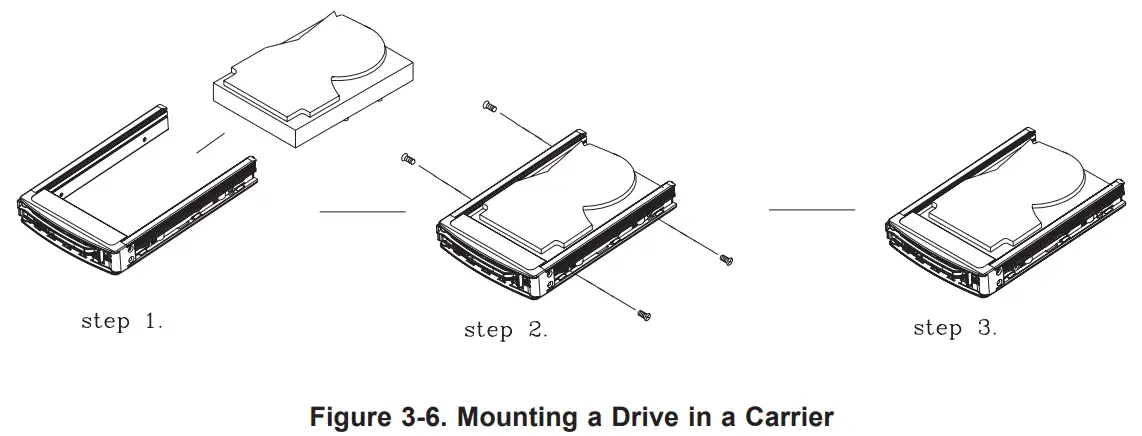
Mounting a Drive in a Drive Carrier
The SATA drive carriers help to promote proper airflow for the system. For this reason, even carriers without SATA drives must remain in the chassis.
- To add a new drive, install it into the carrier with the printed circuit board side facing down so that the mounting holes align with those in the carrier.
- Secure the drive to the carrier with the screws provided, then push the carrier completely into the drive bay. You should hear a *click* when the drive is fully inserted.
This indicates that the carrier has been fully seated and connected to the midplane, which automatically makes the power and logic connections to the hard drive.
Removing a Drive from a Drive Carrier
- Remove the screws that secure the hard drive to the carrier and separate the hard drive from the carrier.
- Replace the carrier back into the drive bay.
Note: Enterprise level hard disk drives are recommended for use in Supermicro chassis and servers. For information on recommended HDDs, visit the Supermicro website at http://www.supermicro.com/products/nfo/storage.cfm
SATA Backplane
The SATA drives plug into a drive backplane. A data cable for each drive and two LED cables need to be connected from the motherboard to the appropriate connectors on the backplane.
Note that you cannot cascade the SATA backplane.
Installing Components in the 5.25″ Drive Bays
The 5049A-TR has two 5.25″ drive bays. Components such as an extra DVD-ROM drive can be installed into these 5.25″ drive bays.
Removing the Empty Drive Bay
- First power down the system.
- Remove the top/left chassis cover to access the drive components.
- With the cover off, remove the screws that secure the drive carrier to the chassis (one side only) then push the entire empty drive carrier out from the back.
Adding a DVD-ROM Drive
- Remove the guide plates (one on each side) from the empty drive carrier and screw them into both sides of the DVD-ROM drive using the holes provided.
- Slide the DVD-ROM into the bay and secure it to the chassis with the drive carrier screws you first removed.
- Attach the power and data cables to the drive.
- Replace the top/left chassis cover and restore power to the system.
System Cooling
Heavy-duty fans provide cooling for the chassis. Four fans are located in the mid-section of the chassis, two fans are located in the rear, and two optional fans can be mounted on the external rear of the chassis, required for passive GPUs. The internal fans come pre-installed on the chassis. Each fan is hot-swappable and can be replaced without removing any connections.
System Fan Failure
Fan speed is controlled by system temperature through IPMI. If a fan fails, the remaining fans will ramp up to full speed. Replace any failed fan at your earliest convenience with the same type and model (the system can continue to run with a failed fan).
Replacing System Fans
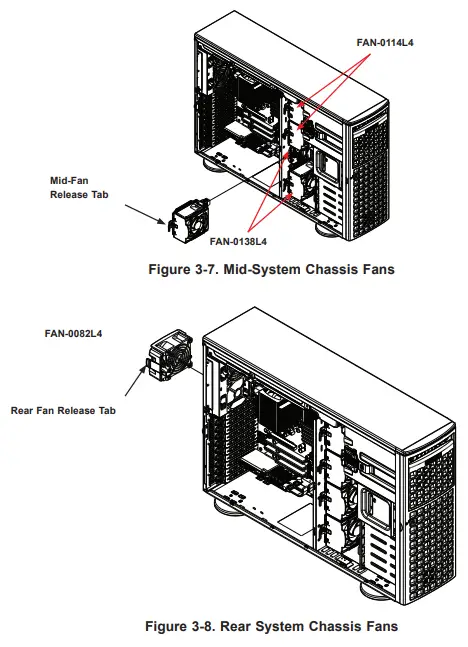
The chassis contains two types of system fans: mid-system fans and rear-system fans.
Replacing Mid-System Fans (FAN-0114L4 and FAN-0138L4)
- Use IPMI to determine which fan has failed. Because the fans are hot-swappable, the system does not need to be powered down.
- Remove the side cover as described in Section 3.2.
- Press the fan release tab and lift the failed fan from the chassis. Mid-fans must be pulled straight out of the chassis. Part numbers: top two fans are FAN-0114L4 and
the bottom two are FAN-0138L4. - Place the new fan into the vacant space in the housing. Make sure the arrows indicating air direction point in the same direction as the arrows on the other fans. As soon as the fan is connected, it will begin working.
Replacing the Rear System Fan (FAN-0082L4)
- Use IPMI to determine which fan has failed.
- Press the rear fan release tab.
- Pull the fan away from the chassis by pulling out the top first.
- Place the new fan in the chassis, inserting the bottom of the fan first.
- Push the fan fully into the housing until the fan clicks into place. Replace the chassis cover.
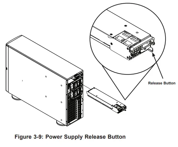
Power Supply
The SuperWorkstation 5049A-TR includes two 1+1 2200W redundant power supplies. These power supplies are auto-switching capable. This enables it to automatically sense and operate at a 100V to 240V input voltage. An amber light will be illuminated on the power supply when the power is off. An illuminated green light indicates that the power supply is operating.
Replacing the Power Supply
- Push the release button on the back of the failed power module.
- Pull the power module out using the handle provided.
- Replace the failed power module with the same model.
- Push the new power module into the power bay until you hear a click.
Chapter 4 Motherboard Connections
This section describes the connections on the motherboard and provides pinout definitions. Note that depending on how the system is configured, not all connections are required. The LEDs on the motherboard are also described here. The motherboard layout indicating component locations may be found in Chapter 1. Please review the Safety Precautions in Appendix B before installing or removing components.
4.1 Power Connections
ATX Power Supply Connector
The 24-pin power supply connector (JPWR2) meets the ATX SSI EPS 12V specification. You must also connect the 8-pin processor power connectors to the power supply.
| ATX Power 24-pin Connector Pin Definitions | |||
| Pin# | Definition | Pin# | Definition |
| 13 | +3.3V | 1 | +3.3V |
| 14 | -12V | 2 | +3.3V |
| 15 | Ground | 3 | Ground |
| 16 | PS_ON | 4 | +5V |
| 17 | Ground | 5 | Ground |
| 18 | Ground | 6 | +5V |
| 19 | Ground | 7 | Ground |
| 20 | Res (NC) | 8 | PWR_OK |
| 21 | +5V | 9 | 5VSB |
| 22 | +5V | 10 | +12V |
| 23 | +5V | 11 | +12V |
| 24 | Ground | 12 | +3.3V |
8-Pin Power Connectors
JPWR1/JPWR3/JPWR4 are 8-pin 12V DC power inputs for the CPU on the X11SPA-T motherboard. Besides the 24-pin ATX PWR (JPWR2), two 12V 8-pin power connections (JPWR1/JPWR3) are required to ensure adequate power supply to the system. Refer to the table below for pin definitions.
| 8-pin Power Connector Pin Definitions | |
| Pin# | Definition |
| 4-Jan | Ground |
| 8-May | P12V (12V Power) |
Required Connection
Important: Please connect the power supplies to the 24-pin power connector (JPWR2) and the 8-pin power connectors (JPWR1/JPWR3/JPWR4) on the motherboard when more than four of the PCI-E slots are populated. Failure to do so may void the manufacturer warranty on your power supply and motherboard.
4.2 Headers and Connectors
Fan Headers
There are ten 4-pin fan headers (FAN1 ~ FAN6, FAN A ~ FAN D) on the motherboard. All these 4-pin fan headers are backward compatible with the traditional 3-pin fan headers. However, fan speed control is available for 4-pin fan headers only by Thermal Management via the IPMI 2.0 interface. Refer to the table below for pin definitions.
| Fan Header Pin Definitions | |
| Pin# | Definition |
| 1 | Ground (Black) |
| 2 | 2.5A/+12V (Red) |
| 3 | Tachometer |
| 4 | PWM_Control |
SGPIO Headers
There are two Serial Link General Purpose Input/Output (I-SGPIO1 and I-SGPIO2) headers located on the motherboard. Refer to the tables below for pin definitions.
| I-SGPIO Header Pin Definitions | |||
| Pin# | Definition | Pin# | Definition |
| 1 | NC | 2 | NC |
| 3 | Ground | 4 | Data |
| 5 | Load | 6 | Ground |
| 7 | Clock | 8 | NC |
NC = No Connection
Disk-On-Module Power Connector
Two power connectors for SATA DOM (Disk-On-Module) devices are located at JSD1 and JSD2. Connect appropriate cables here to provide powerful support for your Serial Link DOM devices.
| DOM Power Pin Definitions | |
| Pin# | Definition |
| 1 | 5V |
| 2 | Ground |
| 3 | Ground |
TPM/Port 80 Header
A Trusted Platform Module (TPM)/Port 80 header is located at JTPM1 to provide TPM support and Port 80 connection. Use this header to enhance system performance and data security. Refer to the table below for pin definitions. Please go to the following link for more information on the TPM: http://www.supermicro.com/manuals/other/TPM.pdf.
| Trusted Platform Module Header Pin Definitions | |||
| Pin# | Definition | Pin# | Definition |
| 1 | +3.3V | 2 | SPI_CS# |
| 3 | RESET# | 4 | SPI_MISO |
| 5 | SPI_CLK | 6 | GND |
| 7 | SPI_MOSI | 8 | NC |
| 9 | +3.3V Stdby | 10 | SPI_IRQ# |
Standby Power Header
The Standby Power header is located at JSTBY1 on the motherboard. You must have a card with a Standby Power connector and a cable to use this feature. Refer to the table below for pin definitions.
| Standby Power Header Pin Definitions | |
| Pin# | Definition |
| 1 | +5V Standby |
| 2 | Ground |
| 3 | No Connection |
Power SMB (I²C) Header
The Power System Management Bus (I²C) connector (JPI2C1) monitors the power supplies, fans, and system temperatures. Refer to the table below for pin definitions.
| Power SMB Header Pin Definitions | |
| Pin# | Definition |
| 1 | Clock |
| 2 | Data |
| 3 | PMBUS_Alert |
| 4 | Ground |
| 5 | +3.3V |
4-pin BMC External I2C Header
A System Management Bus header for IPMI 2.0 is located at JIPMB1. Connect the appropriate cable to use the IPMB I2C connection on your system. Refer to the table below for pin definitions.
| External I2C Header Pin Definitions | |
| Pin# | Definition |
| 1 | Data |
| 2 | Ground |
| 3 | Clock |
| 4 | No Connection |
M.2 Slots
The X11SPA-T motherboard has four M.2 slots. M.2 was formerly known as Next Generation Form Factor (NGFF) and serves to replace mini PCI-E. M.2 allows for a variety of card sizes, increased functionality, and spatial efficiency. The M.2 sockets on the motherboard supports PCI-E 3.0 x4 (32 Gb/s) SSD cards in 2260, 2280, and 22110 form factors.
Power LED/Speaker Connector
Pins 1-3 of JD1 are used for power LED indication, and pins 4-7 are for the speaker. Pleasenote that the speaker connector pins (4-7) are used with an external speaker. If you wish to use the onboard speaker, you should close pins 6-7 with a cap. Refer to the tables below for pin definitions.
| PWR LED Connector Pin Definitions | |
| Pin# | Signal |
| 1 | JD1_PIN1 |
| 2 | FP_PWR_LED |
| 3 | FP_PWR_LED |
| Speaker Connector Pin Definitions | |
| Pin# | Signal |
| 4 | P5V |
| 5 | Key |
| 6 | R_SPKPIN_N |
| 7 | R_SPKPIN |
Overheat/Fan Fail LED Header
Header JOH1-OH is used to connect to an LED indicator to provide warnings of chassis overheating and fan failure. This LED will blink when a fan failure occurs. Refer to the tables below for pin definitions.
| Overheat/Fan Fail LED Header Status | |
| State | Definition |
| Solid | Overheat |
| Blinking | Fan Fail |
| Overheat/Fan Fail LED Header Pin Definitions | |
| Pin# | Signal |
| 1 | Pull high to +3.3V power through 330-ohm resistor |
| 2 | OH Active |
SATA Ports
Eight SATA 3.0 ports are located on the X11SPA-T motherboard supported by the C621 chipset. These SATA ports support RAID 0, 1, 5, and 10. SATA ports provide serial-link signal connections which are faster than the connections of Parallel ATA.
Note: For more information on the SATA HostRAID configuration, please refer to the Intel SATA HostRAID user’s guide is posted on our website at http://www.supermicro.com/support/manuals/.
Chassis Intrusion Header
A Chassis Intrusion header is located at JL1 on the motherboard. Attach the appropriate cable from the chassis to inform you of a chassis intrusion when the chassis is opened. Refer to the table below for pin definitions.
| Chassis Intrusion Header Pin Definitions | |
| Pin# | Definition |
| 1 | Intrusion Input |
| 2 | Ground |
Intel RAID Key Header
Header JRK1 allows the user to enable RAID functions. Refer to the table below for pin definitions.
| Intel RAID Key Header Pin Definitions | |
| Pin# | Defintion |
| 1 | GND |
| 2 | PU 3.3V Stdby |
| 3 | GND |
| 4 | PCH RAID KEY |
4.3 Rear I/O Ports
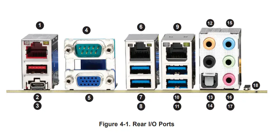
| Rear I/O Ports | |||||
| Item | Description | Item | Description | Item | Description |
| 1 | 1Gb RJ45 Port 1 | 7 | USB 3.2 Gen1 (5G) | 13 | Surround Out |
| 2 | USB 3.2 Gen2x1 (10G) | 8 | USB 3.2 Gen1 (5G) | 14 | S/PDIF Out |
| 3 | USB 3.2 Gen2x1 (10G) | 9 | 10Gb RJ45 Port2 | 15 | Line In |
| 4 | COM1 Port | 10 | USB 3.2 Gen1 (5G) | 16 | Line Out |
| 5 | VGA Port | 11 | USB 3.2 Gen1 (5G) | 17 | Mic In |
| 6 | Dedicated IPMI LAN Port | 12 | Center/LFE Out | 18 | UID Switch |
VGA Port
A video (VGA) port is located next to USB 3.2 Gen2x1 Port 8 (Type C) on the I/O back panel.
COM Connections
Two COM connections (COM1/COM2) are located on the motherboard. COM1 is located on the I/O back panel. COM2 is located next to M.2-C03 PCI-E 3.0 x4.
| COM Connection Pin Definitions | |||
| Pin# | Definition | Pin# | Definition |
| 1 | DCD | 6 | DSR |
| 2 | RXD | 7 | RTS |
| 3 | TXD | 8 | CTS |
| 4 | DTR | 9 | RI |
| 5 | Ground | 10 | N/A |
LAN Ports
Two RJ45 Ethernet LAN ports (LAN1/LAN2) are located on the I/O back panel. In addition, a dedicated IPMI LAN port is located above the USB6/7 ports on the I/O back panel. All of these ports accept RJ45 cables. Please refer to Section 4.6 for LAN LED information.
| LAN Port Pin Definitions | |||
| Pin# | Definition | Pin# | Definition |
| 1 | TD0- | 11 | P3V3_Dual |
| 2 | TD0+ | 12 | Act LED (Yellow) |
| 3 | TD1- | 13 | Link 1000 (Amber) |
| 4 | TD1+ | 14 | Link 100 LED (Green) |
| 5 | TD2- | 15 | GND |
| 6 | TD2+ | 16 | GND |
| 7 | TD3- | 17 | GND |
| 8 | TD3+ | 18 | GND |
| 9 | COMMCT | 19 | GND |
| 10 | GND | 20 | Act LED (Yellow) |
| 9 | TD0+ | 21 | Link 100 LED (Green) |
| 10 | TD0- | 22 | Link 1000 LED (Amber) |
| 11 | TD1+ | 23 | SGND |
| 12 | TD1- | 24 | SGND |
| 13 | TD2+ | 25 | SGND |
| 14 | TD2- | 26 | SGND |
| 15 | TD3+ | ||
| 16 | TD3- | ||
| 17 | GND | ||
| 18 | |||
Universal Serial Bus (USB) Ports
There are four USB 3.2 Gen1 ports (USB4/5, USB6/7) and two USB 3.2 Gen2x1 ports (USB8/9) located on the I/O back panel. The motherboard also has two front access USB 3.2 Gen2x1 headers (USB10, USB11), one front access USB 2.0 header (USB0/1), and one front access USB 3.2 Gen1 header (USB2/3). The USB10 header is Type A and the USB11 header is Type C. The onboard headers can be used to provide front-side USB access with a cable (not included).
| Back Panel USB0/1 (2.0) Pin Definitions | |||
| Pin# | Definition | Pin# | Definition |
| 1 | +5V | 5 | +5V |
| 2 | USB_N | 6 | USB_N |
| 3 | USB_P | 7 | USB_P |
| 4 | Ground | 8 | Ground |
| Front Panel USB2/3, 4/5, 6/7 (3.1 Gen1) Pin Definitions | |||
| Pin# | Definition | Pin# | Definition |
| 1 | +5V | 2 | +5V |
| 3 | USB_N | 4 | USB_N |
| 5 | USB_P | 6 | USB_P |
| 7 | Ground | 8 | Ground |
| 9 | Key | 10 | NC |
| Back Panel USB11 (3.1 Gen2) Pin Definitions | |||
| Pin# | Definition | Pin# | Definition |
| A1 | VBUS | B1 | Power |
| A2 | D- | B2 | USB_N |
| A3 | D+ | B3 | USB_P |
| A4 | GND | B4 | GND |
| A5 | Stda_SSRX- | B5 | USB3_RN |
| A6 | Stda_SSRX+ | B6 | USB3_RP |
| A7 | GND | B7 | GND |
| A8 | Stda_SSTX- | B8 | USB3_TN |
| A9 | Stda_SSTX+ | B9 | USB3_TP |
| Back Panel USB8/9 (3.1 Gen2) Pin Definitions | |||
| Pin# | Definition | Pin# | Definition |
| 1 | VBUS | 19 | Power |
| 2 | Stda_SSRX- | 18 | USB3_RN |
| 3 | Stda_SSRX+ | 17 | USB3_RP |
| 4 | GND | 16 | GND |
| 5 | Stda_SSTX- | 15 | USB3_TN |
| 6 | Stda_SSTX+ | 14 | USB3_TP |
| 7 | GND | 13 | GND |
| 8 | D- | 12 | USB_N |
| 9 | D+ | 11 | USB_P |
| 10 | x | ||
| Front Panel USB10 (3.1 Gen2) Pin Definitions | |||
| Pin# | Definition | Pin# | Definition |
| 1 | VBUS | 5 | SSRX- |
| 2 | USB_N | 6 | SSRX+ |
| 3 | USB_P | 7 | GND |
| 4 | Ground | 8 | SSTX- |
| 9 | SSTX+ | ||
Unit Identifier Switch/UID LED Indicator
A Unit Identifier (UID) switch and an LED indicator are located on the motherboard. The UID switch is located at UID-SW, which is next to the HD AUDIO ports on the back panel. The UID-LED is located next to the switch. When you press the UID switch, the UID LED will be turned on. Press the UID switch again to turn off the LED indicator. The UID indicator provides easy identification of a system unit that may be in need of service.
Note: UID can also be triggered via IPMI on the motherboard. For more information on IPMI, please refer to the IPMI User’s Guide posted on our website at http://www.supermicro.com/products/nfo/IPMI.cfm.
| UID Switch Pin Definitions | |
| Pin# | Definition |
| 1 | Ground |
| 2 | Ground |
| 3 | Button In |
| 4 | Button In |
| UID LED Pin Definitions | |
| Color | Status |
| Blue: On | Unit Identified |
4.4 Front Control Panel
JF1 contains header pins for various buttons and indicators that are normally located on a control panel at the front of the chassis. These connectors are designed specifically for use with a Supermicro chassis.
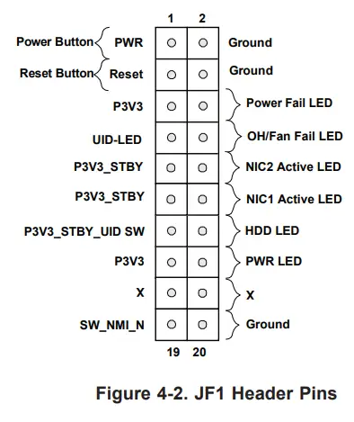
Power Button
The Power Button connection is located on pins 1 and 2 of JF1. Momentarily contacting both pins will power on/off the system. This button can also be configured to function as a suspend button. To turn off the power when the system is in suspend mode, press the button for four seconds or longer. Refer to the table below for pin definitions.
| Power Button Pin Definitions (JF1) | |
| Pins | Definition |
| 1 | Signal |
| 2 | Ground |
Reset Button
The Reset Button connection is located on pins 3 and 4 of JF1. Attach it to a hardware reset switch on the computer case to reset the system. Refer to the table below for pin definitions.
| Reset Button Pin Definitions (JF1) | |
| Pins | Definition |
| 3 | Reset |
| 4 | Ground |
Power Fail LED
The Power Fail LED connection is located on pins 5 and 6 of JF1. Refer to the table below for pin definitions.
| Power Fail LED Pin Definitions (JF1) | |
| Pins | Definition |
| 5 | 3.3V |
| 6 | PWR Supply Fail |
Overheat (OH)/Fan Fail LED
Connect an LED cable to pins 7 and 8 of the Front Control Panel to use the Overheat/Fan Fail LED connections. The LED on pin 8 provides warnings of overheating or fan failure. Refer to the tables below for pin definitions.
| OH/Fan Fail Indicator Status | |
| State | Definition |
| Off | Normal |
| On | Overheat |
| Flashing | Fan Fail |
| OH/Fan Fail LED Pin Definitions (JF1) | |
| Pins | Definition |
| 7 | Blue LED |
| 8 | OH/Fan Fail LED |
NIC1/NIC2 (LAN1/LAN2) LED
The NIC (Network Interface Controller) LED connection for LAN port 1 is located on pins 11 and 12 of JF1, and LAN port 2 is on pins 9 and 10. Attach the NIC LED cables here to display network activity. Refer to the table below for pin definitions.
| LAN1/LAN2 LED Pin Definitions (JF1) | |
| Pins | Definition |
| 9 | NIC 2 Activity LED |
| 11 | NIC 1 Activity LED |
HDD LED
The HDD LED connection is located on pins 13 and 14 of JF1. Attach a cable to pin 14 to show hard drive activity status. Refer to the table below for pin definitions.
| HDD LED Pin Definitions (JF1) | |
| Pins | Definition |
| 13 | 3.3V Stdby |
| 14 | HDD Active |
Power LED
The Power LED connection is located on pins 15 and 16 of JF1. Refer to the table below for pin definitions.
| Power LED Pin Definitions (JF1) | |
| Pins | Definition |
| 15 | 3.3V |
| 16 | PWR LED |
NMI Button
The Non-Maskable Interrupt (NMI) button header is located on pins 19 and 20 of JF1. Refer to the table below for pin definitions.
| NMI Button Pin Definitions (JF1) | |
| Pins | Definition |
| 19 | Control |
| 20 | Ground |
4.5 Jumpers
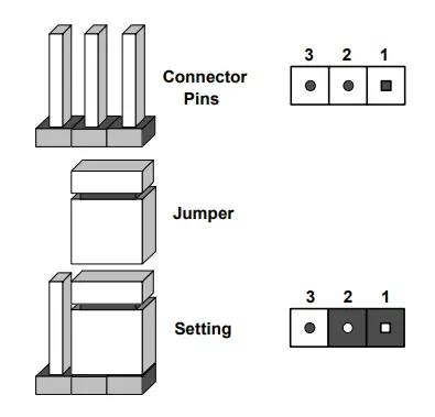
Explanation of Jumpers
To modify the operation of the motherboard, jumpers are used to choose between optional settings. Jumpers create shorts between two pins to change the function associated with it. Pin 1 is identified with a square solder pad on the printed circuit board. See the motherboard layout page for jumper locations.
Note: On a two-pin jumper, “Closed” means the jumper is on both pins, and “Open” indicates the jumper is either on only one pin or has been completely removed.
CMOS Clear
JBT1 is used to clear CMOS, which will also clear any passwords. Instead of pins, this jumper
consists of contact pads to prevent accidentally clearing the contents of CMOS.
To Clear CMOS
- First power down the system and unplug the power cord(s).
- Remove the cover of the chassis to access the motherboard.
- Remove the onboard battery from the motherboard.
- Short the CMOS pads with a metal object such as a small screwdriver for at least four seconds.
- Remove the screwdriver (or shorting device).
- Replace the cover, reconnect the power cord(s), and power on the system.
Notes: Clearing CMOS will also clear all passwords.
Do not use the PW_ON connector to clear CMOS.
 JBT1 contact pads
Watchdog
Watchdog (JWD1) is a system monitor that can reboot the system when a software application hangs. Close pins 1-2 to reset the system if an application hangs. Close pins 2-3 to generate a non-maskable interrupt (NMI) signal for the application that hangs. Refer to the table below for jumper settings. The Watchdog must also be enabled in the BIOS.
| Watchdog Jumper Settings | |
| Jumper Setting | Definition |
| Pins 1-2 | Reset |
| Pins 2-3 | NMI |
| Open | Disabled |
VGA Enable/Disable
Jumper JPG1 allows the user to enable the onboard VGA connector. The default setting is pins 1-2 to enable the connection. Refer to the table below for jumper settings.
| VGA Enable/Disable Jumper Settings | |
| Jumper Setting | Definition |
| Pins 1-2 | Enabled (Default) |
| Pins 2-3 | Disabled |
ME Manufacturing Mode
Close pins 2-3 of Jumper JPME2 to bypass SPI flash security and force the system to operate in manufacturing mode, which will allow the user to flash the system firmware from a host server for system setting modifications. Refer to the table below for jumper settings. The default setting is Normal.
| Manufacturing Mode Jumper Settings | |
| Jumper Setting | Definition |
| Pins 1-2 | Normal (Default) |
| Pins 2-3 | Manufacturing Mode |
1Gb/10Gb LAN Enable/Disable
JPL1 and JPL2 allows the user to enable or disable the 1Gb/10Gb LAN Ports. The default setting is Enabled.
| 1Gb/10Gb LAN Enable/Disable Jumper Settings | |
| Jumper Setting | Definition |
| Pins 1-2 | Enabled (Default) |
| Pins 2-3 | Disabled |
USB Wake-Up
This jumper allows you to “wake up” the system by pressing a key on the USB keyboard or by clicking the USB mouse of your system. Jumper JPUSB1 is used together with the USB Wake-Up feature in BIOS. Both JPUSB1 and the BIOS setting must be enabled to use this feature. The default setting is Enabled.
Note: Please be sure to remove all other USB devices from the USB ports whose jumpers are set to disabled before the system goes into standby mode.
Note: X11SPA-T does not support S3 and S4 power mode states.
4.6 LED Indicators
Rear Unit ID LED
A rear UID LED indicator (UID-LED) is located near the UID switch on the I/O back panel.
This UID indicator provides easy identification of a system unit that may need service.
| UID-LED LED Indicator | |
| LED Color | Definition |
| Blue: On | Unit Identified |
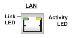
LAN LEDs
Two LAN ports are located on the I/O back panel of the motherboard. This Ethernet LAN port has two LEDs (Light Emitting Diode). The yellow LED indicates activity, while the Link LED may be green, amber, or off to indicate the speed of the connection. Refer to the tables below for more information.
| GLAN Activity Indicator LED Settings | ||
| Color | Status | Definitio |
| Yellow | Flashing | Active |
| 1Gbit LAN Link Indicator LED Settings | |
| LED Color | Definition |
| Off | No Connection |
| Amber | 100Mbps/10Mbps |
| Green | 1 Gbps |
| 10Gbit LAN Link Indicator LED Settings | |
| LED Color | Definition |
| Off | No Connection |
| Amber | 5Gbps/2.5Gbps/1Gbps/100Mbps |
| Green | 10 Gbps. |
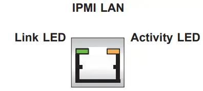
IPMI LAN LEDs
In addition to LAN1 and LAN2, an IPMI LAN is also located on the I/O back panel. The amber LED on the right indicates activity, while the green LED on the left indicates the speed of the connection. Refer to the table below for more information.
LAN 1/LAN 2
| IPMI LAN (X8ST3-F) IPMI LAN LED Settings | ||
| Color/State | Definition | |
| Link (Left) | Green: Solid Amber: Solid | 100 Mbps 1Gbps |
| Activity (Right) | Amber: Blinking | Active |
M.2 LED
The M.2 LED is located at LE3, LE4, LE5, and LE6 on the motherboard. When the M.2 LED is blinking, its corresponding M.2 device functions normally. Refer to the table below for more information.
| M.2 LED Settings | |
| LED Color | Definition |
| Green: Blinking | Device Working |
Onboard Power LED
The Onboard Power LED is located at LEDPWR on the motherboard. When this LED is on, the system is on. Be sure to turn off the system and unplug the power cord before removing or installing any component. Refer to the table below for more information.
| Onboard Power LED Indicator | |
| LED Color | Definition |
| Off | System Off (power cable not connected) |
| Green | System On |
BMC Heartbeat LED
A BMC Heartbeat LED is located at LEDBMC on the motherboard. When LEDBMC is blinking, the BMC is functioning normally. Refer to the table below for more information.
| BMC Heartbeat LED Indicator | |
| LED Color | Definition |
| Green: Blinking | BMC Normal |
Chapter 5 Software
After the hardware has been installed, you can install the Operating System (OS), configure RAID settings, and install the drivers.
5.1 Microsoft Windows OS Installation
If you will be using RAID, you must configure RAID settings before installing the Windows OS and the RAID driver. Refer to the RAID Configuration User Guides posted on our website at www.supermicro.com/support/manuals.
Installing the OS
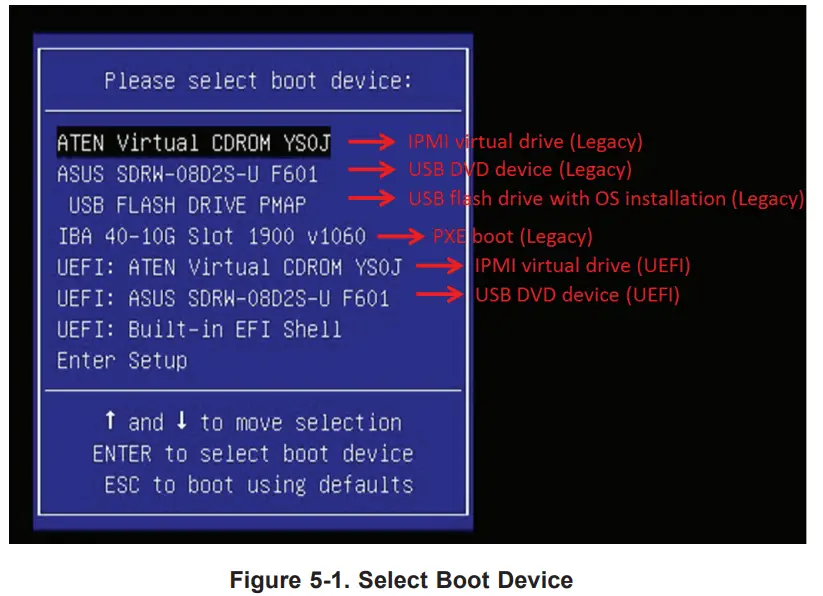
- Create a method to access the MS Windows installation ISO file. That might be a DVD, perhaps using an external USB/SATA DVD drive, or a USB flash drive, or the IPMI KVM console.
- Retrieve the proper RST/RSTe driver. Go to the Supermicro web page for your motherboard and click on “Download the Latest Drivers and Utilities”, select the proper
driver, and copy it to a USB flash drive. - Boot from a bootable device with Windows OS installation. You can see a bootable device list by pressing F11 during the system startup.

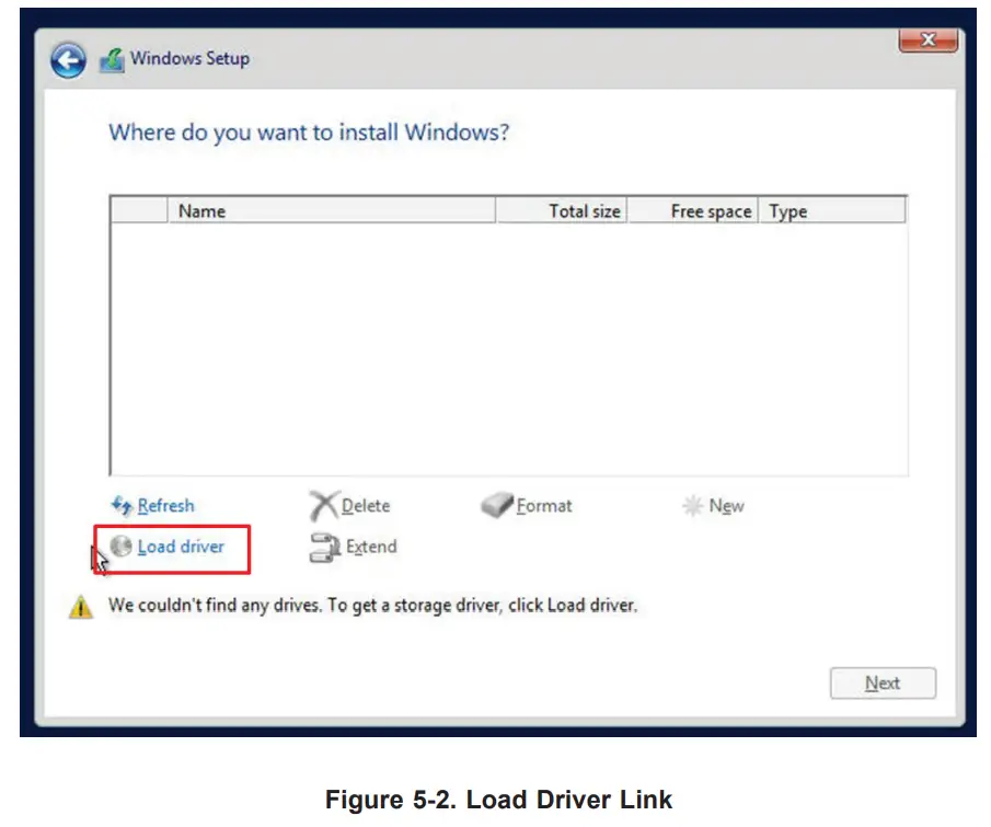
- During Windows Setup, continue to the dialog where you select the drives on which to install Windows. If the disk you want to use is not listed, click on “Load driver” link at the bottom left corner.

To load the driver, browse the USB flash drive for the proper driver files.
• For RAID, choose the SATA/sSATA RAID driver indicated then choose the storage drive on which you want to install it.
• For non-RAID, choose the SATA/sSATA AHCI driver indicated then choose the storage
drive on which you want to install it. - Once all devices are specified, continue with the installation.
- After the Windows OS installation has completed, the system will automatically reboot multiple times.
5.2 Driver Installation
The Supermicro website contains drivers and utilities for your system at https://www.supermicro.com/wftp/driver. Some of these must be installed, such as the chipset driver.
After accessing the website, go into the CDR_Images (in the parent directory of the above link) and locate the ISO file for your motherboard. Download this file to a USB flash drive or a DVD. (You may also use a utility to extract the ISO file if preferred.)
Another option is to go to the Supermicro website at http://www.supermicro.com/products/. Find the product page for your motherboard, and “Download the Latest Drivers and Utilities”. Insert the flash drive or disk and the screenshot shown below should appear.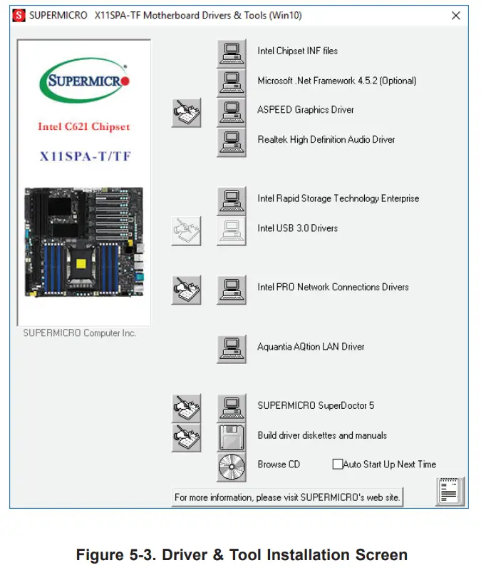
Note: Click the icons showing handwriting on paper to view the readme files for each item. Click the computer icons to the right of these items to install each item (from top to the bottom) one at a time. After installing each item, you must reboot the system before moving on to the next item on the list. The bottom icon with a CD on it allows you to view the entire contents.
5.3 SuperDoctor® 5
The Supermicro SuperDoctor 5 is a program that functions in a command-line or web-based interface for Windows and Linux operating systems. The program monitors such system health information as CPU temperature, system voltages, system power consumption, and fan speed, and provides alerts via email or Simple Network Management Protocol (SNMP). SuperDoctor 5 comes in local and remote management versions and can be used with Nagiosto to maximize your system monitoring needs. With SuperDoctor 5 Management Server (SSM Server), you can remotely control power on/off and reset chassis intrusion for multiple systems with SuperDoctor 5 or IPMI. SuperDoctor 5 Management Server monitors HTTP, FTP, and SMTP services to optimize the efficiency of your operation.
Note: The default User Name and Password for SuperDoctor 5 is ADMIN / ADMIN.
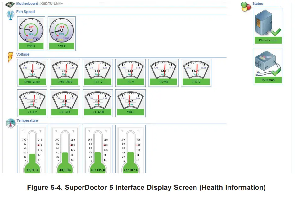
5.4 IPMI
The X11SPA-T supports the Intelligent Platform Management Interface (IPMI). IPMI is used to provide remote access, monitoring, and management. There are several BIOS settings that are related to IPMI. For general documentation and information on IPMI, please visit our website at: http://www.supermicro.com/products/nfo/IPMI.cfm.
Chapter 6 UEFI BIOS
6.1 Introduction
This chapter describes the AMIBIOS™ Setup utility for the X11SPA-T motherboard. The is stored on a chip and can be easily upgraded using a flash program.
Note: Due to periodic changes to the BIOS, some settings may have been added or deleted and might not yet be recorded in this manual. Please refer to the Manual Download area of our website for any changes to BIOS that may not be reflected in this manual.
Starting the Setup Utility
To enter the BIOS Setup Utility, hit the <Delete> key while the system is booting up. (In most cases, the <Delete> key is used to invoke the BIOS setup screen. There are a few
cases when other keys are used, such as <F1>, <F2>, etc.) Each main BIOS menu option is described in this manual.
The Main BIOS screen has two main frames. The left frame displays all the options that can be configured. “Grayed-out” options cannot be configured. The right frame displays the key legend. Above the key legend is an area reserved for a text message. When an option is selected in the left frame, it is highlighted in white. Often a text message will accompany it.
(Note that BIOS has default text messages built-in. We retain the option to include, omit, or change any of these text messages.) Settings printed in Bold are the default values.
A “▶” indicates a submenu. Highlighting such an item and pressing the <Enter> key will open the list of settings within that submenu.
The BIOS setup utility uses a key-based navigation system called hotkeys. Most of these hotkeys (<F1>, <F10>, <Enter>, <ESC>, <Arrow> keys, etc.) can be used at any time during the setup navigation process.
6.2 Main Setup
When you first enter the AMI BIOS setup utility, you will enter the Main setup screen. You can always return to the Main setup screen by selecting the Main tab at the top of the screen. The Main BIOS setup screen is shown below and the following features will be displayed:
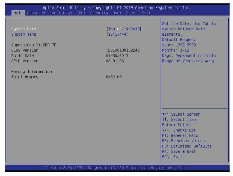
System Date/System Time
Use this feature to change the system date and time. Highlight System Date or System Time using the arrow keys. Enter new values using the keyboard. Press the <Tab> key or the arrow keys to move between fields. The date must be entered in MM/DD/YYYY format. The time is entered in HH:MM: SS format.
Note: The time is in the 24-hour format. For example, 5:30 P.M. appears as 17:30:00. The date’s default value is the BIOS build date after RTC reset.
Supermicro X11SPA-T
BIOS Version
This feature displays the version of the BIOS ROM used in the system.
Build Date
This feature displays the date when the version of the BIOS ROM used in the system was built.
CPLD Version
This feature displays the Complex Programmable Logic Device version.
Memory Information
Total Memory
This feature displays the total size of memory available in the system.
6.3 Advanced Setup Configurations
Use the arrow keys to select the Advanced menu and press <Enter> to access the submenu items:
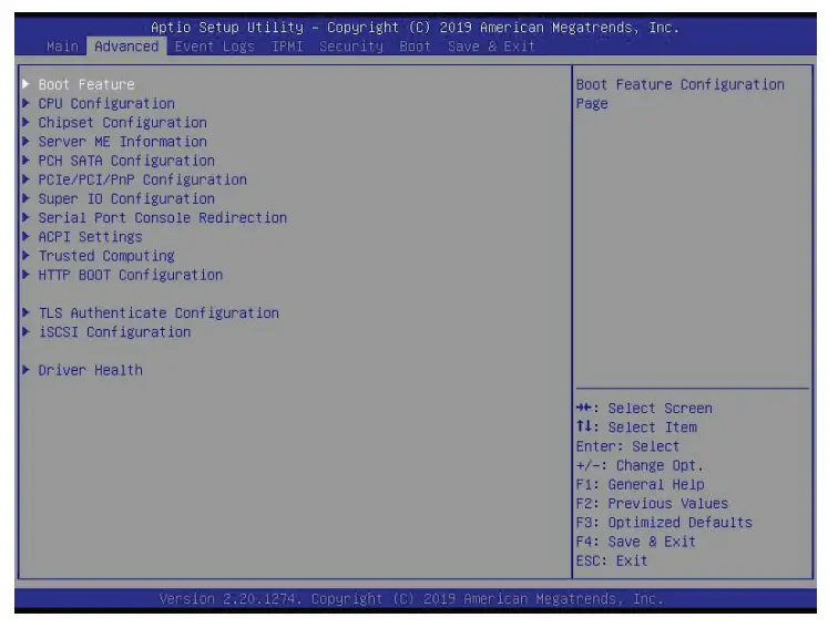
Warning: Take caution when changing the Advanced settings. An incorrect value, a very high DRAM frequency, or an incorrect DRAM timing setting may make the system unstable. When this occurs, revert to the default manufacturer settings.
- Boot Feature
Quiet Boot
Use this feature to select the screen display between the POST messages and the OEM logo upon bootup. Select Disabled to display the POST messages. Select Enabled to display the OEM logo instead of the normal POST messages. The options are Disabled and Enabled.
Option ROM Messages
Use this feature to set the display mode for the Option ROM. Select Keep Current to display the current AddOn ROM setting. Select Force BIOS to use the Option ROM display set by the system BIOS. The options are Force BIOS and Keep Current.
Bootup NumLock State
Use this feature to set the Power-on state for the <Numlock> key. The options are On and Off.
Wait For “F1” If Error
Use this feature to force the system to wait until the “F1” key is pressed if an error occurs. The options are Disabled and Enabled.
INT19 (Interrupt 19) Trap Response
Interrupt 19 is the software interrupt that handles the boot disk function. When this feature is set to Immediate, the ROM BIOS of the host adapters will “capture” Interrupt 19 at bootup immediately and allow the drives that are attached to these host adapters to function as bootable disks. If this feature is set to Postponed, the ROM BIOS of the host adapters will not capture Interrupt 19 immediately and allow the drives attached to these adapters to function as bootable devices at bootup. The options are Immediate and Postponed.
Re-try Boot
If this feature is enabled, the BIOS will automatically reboot the system from a specified boot device after its initial boot failure. The options are Disabled, Legacy Boot, and EFI Boot.
Install Windows 7 USB Support
Enable this feature to use the USB keyboard and mouse during the Windows 7 installation since the native XHCI driver support is unavailable. Use a SATA optical drive as a USB drive, and USB CD/DVD drives are not supported. Disable this feature after the XHCI driver has been installed in Windows. The options are Disabled and Enabled.
Port 61h Bit-4 Emulation
Select Enabled to enable the emulation of Port 61h bit-4 toggling in SMM (System Management Mode). The options are Disabled and Enabled.
Power Configuration
Watch Dog Function
If enabled, the Watch Dog Timer will allow the system to reset or generate NMI based on jumper settings when it is expired for more than five minutes. The options are Disabled and Enabled.
Restore on AC Power Loss
Use this feature to set the power state after a power outage. Select Stay Off for the system power to remain off after a power loss. Select Power On for the system power to be turned on after a power loss. Select Last State to allow the system to resume its last power state before a power loss. The options are Stay Off, Power On, and Last State.
Power Button Function
This feature controls how the system shuts down when the power button is pressed. Select 4 Seconds Override for the user to power off the system after pressing and holding the power button for four seconds or longer. Select Instant Off to instantly power off the system as soon as the user presses the power button. The options are Instant Off and 4 Seconds Override.
- CPU Configuration
The following CPU information will display:
- Processor BSP Revision
- Processor Socket
- Processor ID
- Processor Frequency
- Processor Max Ratio
- Processor Min Ratio
- Microcode Revision
- L1 Cache RAM
- L2 Cache RAM
- L3 Cache RAM
- Processor 0 Version
- Intel(R) Xeon(R) Gold 5118 CPU @ 2.30GHz
Hyper-Threading (ALL) (Available when supported by the CPU)
Select Enable to support Intel Hyper-threading Technology to enhance CPU performance.
The options are Disable and Enable.
Cores Enabled
Use this feature to enable or disable CPU cores in the processor specified by the user. The default setting is 0.
Monitor/Mwait
This feature allows the user to configure Monitor/Mwait. The options are Disable and Enable.
Execute Disable Bit (Available if supported by the OS & the CPU)
Select Enable to enable the Execute-Disable Bit, which will allow the processor to designate areas in the system memory where an application code can execute and where it cannot, thus preventing a worm or a virus from flooding illegal codes to overwhelm the processor or damage the system during an attack. The options are Disable and Enable. (Refer to the Intel and Microsoft® websites for more information.)
Intel Virtualization Technology
Use this feature to enable the Vanderpool Technology. This technology allows the system to run several operating systems simultaneously. The options are Disable and Enable.
PPIN Control
Select Unlock/Enable to use the Protected Processor Inventory Number (PPIN) in the system.
The options are Unlock/Disable and Unlock/Enable.
Hardware Prefetcher (Available when supported by the CPU)
If set to Enable, the hardware prefetcher will prefetch streams of data and instructions from the main memory to the L2 cache to improve CPU performance. The options are Disable and Enable.
Adjacent Cache Prefetch (Available when supported by the CPU)
The CPU prefetches the cache line for 64 bytes if this feature is set to Disabled. The CPU prefetches both cache lines for 128 bytes as comprised if this feature is set to Enable. The options are Enable and Disable.
DCU Streamer Prefetcher (Available when supported by the CPU)
Select Enable to enable the DCU (Data Cache Unit) Streamer Prefetcher which will stream and prefetch data and send it to the Level 1 data cache to improve data processing and system performance. The options are Disable and Enable.
DCU IP Prefetcher (Available when supported by the CPU)
Select Enable for DCU (Data Cache Unit) IP Prefetcher support, which will prefetch IP addresses to improve network connectivity and system performance. The options are Enable and Disable.
LLC Prefetch
If set to Enable, the hardware prefetcher will prefetch streams of data and instructions from the main memory to the L3 cache to improve CPU performance. The options are Disable and Enable.
Extended APIC
Select Enable to activate APIC (Advanced Programmable Interrupt Controller) support. The options are Disable and Enable.
AES-NI
Select Enable to use the Intel Advanced Encryption Standard (AES) New Instructions (NI) to ensure data security. The options are Disable and Enable.
- Advanced Power Management Configuration
Power Technology
Select Energy Efficient to support power-saving mode. Select Custom to customize system power settings. Select Disabled to disable power-saving settings. The options are Disable, Energy Efficient, and Custom.
*If the feature is set to Custom, the following features will display:
Power Performance Tuning (Available when “Power Technology” is set to Custom) Select BIOS to allow the system BIOS to configure the Power-Performance Tuning Bias setting below. The options are OS Controls EPB and BIOS Controls EPB. ENERGY_PERF_BIAS_CFG mode (ENERGY PERFORMANCE BIAS CONFIGURATION Mode) (Available when supported by the Processor and when “Power Performance Tuning” is set to BIOS Controls EPB)
Use this feature to set the processor power use policy to achieve the desired operation settings for your machine by prioritizing system performance or energy savings. Select Maximum Performance to maximize system performance (to its highest potential); however, this may result in maximum power consumption as energy is needed to fuel the processor frequency. The higher the performance is, the higher the power consumption will be. Select Max Power Efficient to maximize power saving; however, system performance may be substantially impacted because limited power use decreases the processor frequency. The options are Performance, Balanced Performance, Balanced Power, and Power. - CPU P State Control
This feature allows the user to configure the following CPU power settings: \SpeedStep (P-States)
Intel SpeedStep Technology allows the system to automatically adjust processor voltage and core frequency to reduce power consumption and heat dissipation. The options are Disable and Enable. EIST PSD Function This feature allows the user to choose between Hardware and Software to control the processor’s frequency and performance (P-state). In HW_ALL mode, the processor hardware is responsible for coordinating the P-state, and the OS is responsible for keeping the P-state request up to date on all logical Processors. In SW_ALL mode, the OS Power Manager is responsible for coordinating the P-state and must initiate the transition on all Logical Processors. In SW_ANY mode, the OS Power Manager is responsible for coordinating the P-state and may initiate the transition on any Logical Processors. The options are HW_ALL, SW_ALL, and SW_ANY.
Turbo Mode
This feature will enable dynamic control of the processor, allowing it to run above stock frequency. The options are Disable and Enable. - Hardware PM State Control
Hardware P-States
This feature allows the user to select between OS and hardware-controlled P-states. Selecting Native Mode allows the OS to choose a P-state. Selecting Out of Band Mode
allows the hardware to autonomously choose a P-state without OS guidance. Selecting Native Mode with No Legacy Support functions as Native Mode with no support for older hardware. The options are Disable, Native Mode, Out of Band Mode, and Native Mode with No Legacy Support. - CPU C State Control
Autonomous Core C-State
Enabling this feature allows the hardware to autonomously choose to enter a C-state based on power consumption and clock speed. The options are Disable and Enable.
CPU C6 Report
Select Enable to allow the BIOS to report the CPU C6 State (ACPI C3) to the operating system. During the CPU C6 State, the power to all cache is turned off. The options are Disable, Enable, and Auto.
Enhanced Halt State (C1E)
Select Enable to use Enhanced Halt State technology, which will significantly reduce the CPU’s power consumption by reducing its clock cycle and voltage during a Halt-state. The options are Disable and Enable. - Package C State Control
Package C State
This feature allows the user to set the limit on the C State package register. The options are C0/C1 state, C2 state, C6 (Non Retention) state, C6 (Retention) state, No Limit, and Auto. - CPU T State Control
Software Controlled T-States
Use this feature to enable Software Controlled T-States. The options are Disable and
Enable. - Chipset Configuration
Warning: Setting the wrong values in the following features may cause the system to malfunction. - North Bridge
This feature allows the user to configure the following North Bridge settings. - UPI Configuration
The following UPI information will display: - Number of CPU
- Number of Active UPI Link
- Current UPI Link Speed
- Current UPI Link Frequency
- UPI Global MMIO Low Base / Limit
- UPI Global MMIO High Base / Limit
- UPI Pci-e Configuration Base / Size
Degrade Precedence
Use this feature to set degrade precedence when system settings are in conflict. Select
Topology Precedence to degrade Features. Select Feature Precedence to degrade Topology.
The options are Topology Precedence and Feature Precedence.
Link L0p Enable
Select Enable for the QPI to enter the L0p state for power saving. The options are Disable, Enable, and Auto.
Link L1 Enable
Select Enable for the QPI to enter the L1 state for power saving. The options are Disable, Enable, and Auto.
IO Directory Cache (IODC)
IO Directory Cache is an 8-entry cache that stores the directory state of remote IIO writes and memory lookups and saves directory updates. Use this feature to lower cache-to-cache (C2C) transfer latencies. The options are Disable, Auto, Enable for Remote InvItoM Hybrid Push, InvItoM AllocFlow, Enable for Remote InvItoM Hybrid AllocNonAlloc, and Enable for Remote InvItoM and Remote WCiLF.
SNC
Select Enable to use the “Sub NUMA (Non-Uniform Memory Access) Cluster” (SNC) memory scheme, which supports full SNC (2-cluster) interleave and 1-way IMC interleave. Select Auto for 1-cluster or 2-cluster support depending on the status of IMC (Integrated Memory Controller) Interleaving. The options are Disable, Enable, and Auto.
XPT Prefetch
Select Enable for Extended (Xtended) Prediction Table (XPT) Prefetch support which will allow a read request to be sent to the memory controller requesting the prefetch
in parallel to an LLC (Last Level Cache) look-up. The options are Disable and Enable.
KTI Prefetch
KTI Prefetch is a feature that enables memory read to start early on a DDR bus, where the KTI Rx path will directly create a Memory Speculative Read command to the memory controller. The options are Disable and Enable.
Local/Remote Threshold
Use this feature to configure the threshold settings for local and remote systems that are connected to the network. The options are Disable, Auto, Low, Medium, and High.
Stale AtoS
Select Enable to remove the contents and the structures of the files that are no longer needed in the remote host server but are still in use by the local client machine from
Directory A to Directory S in the NFS (Network File System) to optimize system performance.
The options are Disable, Enable, and Auto.
LLC Dead Line Alloc
Select Enable to opportunistically fill the deadlines in LLC (Last Level Cache). The options are Disable, Enable, and Auto.
Isoc Mode
Select Enable for Isochronous support to meet QoS (Quality of Service) requirements.
This feature is especially important for Virtualization Technology. The options are Disable, Enable, and Auto.
- Memory Configuration
Enforce POR
Select POR (Plan of Record) to enforce POR restrictions on DDR4 frequency and voltage programming.
The options are POR andDisable.
PPR Type
Use this feature to select Post Package Repair Type. The options are Auto, Hard PPR, Soft PPR, and PPR Disabled.
Memory Frequency
Use this feature to set the maximum memory frequency for onboard memory modules.
The options are Auto, 1866, 2000, 2133, 2400, 2666, and 2933.
Data Scrambling for DDR4
Use this feature to enable or disable data scrambling for DDR4 memory. The options are Auto, Disable, and Enable.
tCCD_L Relaxation
Select Enable to get TCDD settings from SPD (Serial Presence Detect) and implement into memory RC code to improve system reliability. Select Disable for TCCD to follow Intel POR. The options are Auto and Disable.
tRWSR Relaxation
Select Enable to use the same tRWSR DDR timing setting among all memory channels, in which case, the worst case value among all channels will be used. Select Disable to use different values for the tRWSR DDR timing settings for different channels as trained. The options are Disable and Enable.
2x Refresh
Use this feature to select the memory controller refresh rate to 2x refresh mode. The options are Auto and Enable.
Page Policy
Use this feature to set the page policy for onboard memory support. The options are Auto, Closed, and Adaptive.
IMC Interleaving
Use this feature to configure interleaving settings for the IMC (Integrated Memory Controller), which will improve memory performance. The options are Auto, 1-way
Interleave, and 2-way Interleave. - Memory Topology
This feature displays the information of onboard memory modules as detected by the BIOS. - Memory RAS Configuration
Static Virtual Lockstep Mode Select Enable to run the system’s memory channels in lockstep mode to minimize memory access latency. The options are Disable and Enable.
Mirror Mode
This feature allows memory to be mirrored between two channels, providing 100% redundancy. The options are Disable, Mirror Mode 1LM, and Mirror Mode 2LM. Memory Rank Sparing
Select Enable to enable memory-sparing support for memory ranks to improve memory performance. The options are Disable and Enable.
Correctable Error Threshold
Use this feature to specify the threshold value for correctable memory-error logging, which sets a limit on the maximum number of events that can be logged in the memory error log at a given time. The default setting is 100.
Intel® Run Sure
Select Enable to support Intel Run Sure Technology to further enhance critical data protection and to increase system uptime and resiliency. The options are Disable and Enable.
SDDC Plus One
Single Device Data Correction (SDDC) organizes data in a single bundle (x4/x8 DRAM). If any or all the bits become corrupted, corrections occur. The x4 condition is corrected on all cases. The x8 condition is corrected only if the system is in Lockstep Mode. The options are Disable and Enable.
ADDDC Sparing
Adaptive Double Device Data Correction (ADDDC) Sparing detects when the predetermined threshold for correctable errors is reached, copying the contents of the failing DIMM to spare memory. The failing DIMM or memory rank will then be disabled. The options are Disable and Enable.
Patrol Scrub
Patrol Scrubbing is a process that allows the CPU to correct correctable memory errors detected on a memory module and send the correction to the requestor (the original source). When this feature is set to Enable, the IO hub will read and write back one cache line every 16K cycles if there is no delay caused by internal processing. By using this method, roughly 64 GB of memory behind the IO hub will be scrubbed every day. The options are Disable and Enable.
Patrol Scrub Interval
This feature allows you to decide how many hours the system should wait before the next complete patrol scrub is performed. Use the keyboard to enter a value from 0-24. The default setting is 24. - IIO Configuration
EV DFX Features
When this feature is set to Enable, the EV_DFX Lock Bits that are located on a processor will always remain clear during electric tuning. The options are Disable and Enable. - CPU Configuration
IOU1 (II0 PCIe Br2)
This feature configures the PCI-E port Bifuraction setting for a PCI-E port specified by the user. The options are x4x4x4x4, x4x4x8, x8x4x4, x8x8, x16, and Auto.
IOU2 (II0 PCIe Br3)
This feature configures the PCI-E port Bifuraction setting for a PCI-E port specified by the user. The options are x4x4x4x4, x4x4x8, x8x4x4, x8x8, x16, and Auto. - CPU SLOT7 PCI-E 3.0 x16/CPU SLOT1 PCI-E 3.0 x16/M.2C01 PCI-E
3.0 x4/M.2C02 PCI-E 3.0 x4/M.2C03 PCI-E 3.0 x4/M.2C04 PCI-E 3.0 x4
Link Speed
Use this feature to select the link speed for the PCI-E port specified by the user. The options are Auto, Gen 1 (2.5 GT/s), Gen 2 (5 GT/s), and Gen 3 (8 GT/s).
The following information will also be displayed:
• PCI-E Port Link Status
• PCI-E Port Link Max
• PCI-E Port Link Speed
PCI-E Port Max Payload Size
Selecting Auto for this feature will enable the motherboard to automatically detect the maximum Transaction Layer Packet (TLP) size for the connected PCI-E device,
allowing for maximum I/O efficiency. Selecting 128B or 256B will designate a maximum packet size of 128 or 256. The options are 128B, 256B, and Auto. - IOAT Configuration
Disable TPH
TPH is used for data tagging with a destination ID and a few important attributes. It can send critical data to a particular cache without writing through to memory. Select
No in this feature for TLP Processing Hint support, which will allow a “TPL request” to provide “hints” to help optimize the processing of each transaction that occurred in the
target memory space. The options are No and Yes.
Prioritize TPH
Use this feature to enable Prioritize TPH support. The options are Enable and Disable.
Relaxed Ordering
Select Enable to enable Relaxed Ordering support, which will allow certain transactions to violate the strict-ordering rules of PCI buses for a transaction to be completed prior to other transactions that have already been enqueued. The options are Disable and Enable.
- Intel® VT for Directed I/O (VT-d)
Intel® VT for Directed I/O (VT-d)
Select Enable to use Intel Virtualization Technology for Direct I/O VT-d support by reporting the I/O device assignments to the VMM (Virtual Machine Monitor) through the DMAR ACPI tables. This feature offers fully-protected I/O resource sharing across Intel platforms, providing greater reliability, security, and availability in networking and data-sharing. The options are Enable and Disable.
ACS Control
This feature allows users to choose whether they want to enable or disable PCI-E Access Control Services (ACS) Extended Capability. The options are Enable and Disable.
Interrupt Remapping
Use this feature to enable Interrupt Remapping support, which detects and controls external interrupt requests. The options are Enable and Disable.
PassThrough DMA
Use this feature to allow devices such as network cards to access the system memory without using a processor. Select Enable to use the Non-Isoch VT-d Engine Pass Through Direct Memory Access (DMA) support. The options are Enable and Disable.
ATS
Use this feature to enable Non-Isoch VT-d Engine Address Translation Services (ATS) support. ATS translates virtual addresses to physical addresses. The options are Enable and Disable.
Posted Interrupt
Use this feature to enable VT-d Posted Interrupt. The options are Enable and Disable.
Coherency Support (Non-Isoch)
Use this feature to maintain setting coherency between processors or other devices. Select Enable for the Non-Isoch VT-d engine to pass through DMA to enhance system
performance. The options are Enable and Disable.
- Intel® VMD Technology
- Intel® VMD for Volume Management Device on CPU1
VMD Config for PStack0
Intel® VMD for Volume Management Device
Select Enable to use the Intel Volume Management Device Technology for this stack.
The options are Disable and Enable.
*If the feature above is set to Enable, the following features will become available for configuration:
CPU SLOT2/3/4/5 PCI-E 3.0 VMD (Available when the device is detected by the system)
Select Enable to use the Intel Volume Management Device Technology for this specific root port. The options are Disable and Enable.
Hot Plug Capable (Available when the device is detected by the system)
Use this feature to enable hotplug support for PCI-E root ports 1A~1D. The options are Disable and Enable.
VMD Config for PStack1
Intel VMD for Volume Management Device
Select Enable to use the Intel Volume Management Device Technology for this stack.
The options are Disable and Enable.
*If the feature above is set to Enable, the following features will become available for configuration:
CPU SLOT7 PCI-E 3.0 x16 VMD/CPU SLOT6 PCI-E 3.0 x8 VMD (Available when the device is detected by the system) Select Enable to use the Intel Volume Management device Technology for this specific root port. The options are Disable and Enable. Hot Plug Capable (Available when the device is detected by the system)
Use this feature to enable hotplug support for PCI-E root ports 2A~2D. The options are Disable and Enable.
VMD Config for PStack2
Intel® VMD for Volume Management Device
Select Enable to use the Intel Volume Management Device Technology for this stack.
The options are Disable and Enable.
*If the feature above is set to Enable, the following features will become available for configuration:
CPU SLOT1 PCI-E 3.0 x16 VMD/M.2C01 PCI-E 3.0 x4 VMD/M.2C02 PCI-E 3.0 x4 VMD/M.2C03 PCI-E 3.0 x4 VMD/M.2C04 PCI-E 3.0 x4 VMD (Available when the device is detected by the system) Select Enable to use the Intel Volume Management Device Technology for this specific root port. The options are Disable and Enable.
Hot Plug Capable (Available when the device is detected by the system) Use this feature to enable hotplug support for PCI-E root ports 3A~3D. The options are Disable and Enable. PCI-E Completion Timeout Disable Use this feature to enable PCI-E Completion Timeout support for electric tuning. The options are Yes, No, and Per-Port.
- South Bridge
The following USB information will display: - USB Module Version
- USB Devices
Legacy USB Support
This feature enables support for USB 2.0 and older. The options are Enabled, Disabled, and Auto.
XHCI Hand-off
When this feature is disabled, the motherboard will not support USB 3.0. The options are Enabled and Disabled.
Port 60/64 Emulation
This feature allows legacy I/O support for USB devices like mice and keyboards. The options are Enabled and Disabled.
PCIe PLL SSC
Select Enable for PCH PCI-E Spread Spectrum Clocking support, which will allow the BIOS to monitor and attempt to reduce the level of Electromagnetic Interference caused by the components whenever needed. The options are Enable and Disable.
Azalia
Use this feature to enable or disable Azalia audio devices. If Auto is selected, BIOS will automatically enable Azalia once an Azalia device is detected. The options are Enable,
Disable, and Auto.
Azalia PME Enable
Use this feature to enable or disable PME (Power Management Event) for Azalia. The options are Enable and Disable.
- Workstation Me Configuration
The following General ME Configuration will display:
• Oper. Firmware Version
• Me Firmware
• Me Firmware SKU
• Backup Firmware Version
• Recovery Firmware Version
• ME Firmware Status #1
• ME Firmware Status #2
• Current State
• Error Code - PCH SATA Configuration
When this submenu is selected, the AMI BIOS automatically detects the presence of the SATA devices that are supported by the Intel PCH chip and displays the following features:
SATA Controller
This feature enables or disables the onboard SATA controller supported by the Intel PCH chip. The options are Disable and Enable.
Configure SATA as
Select AHCI to configure a SATA drive specified by the user as an AHCI drive. Select RAID to configure a SATA drive specified by the user as a RAID drive. The options are AHCI and RAID.
SATA HDD Unlock
This feature allows the user to remove any password-protected SATA disk drives. The options are Enable and Disable.
Aggressive Link Power Management
When this feature is set to Enable, the SATA AHCI controller manages the power usage of the SATA link. The controller will put the link in a low power mode during extended periods of I/O inactivity and will return the link to an active state when I/O activity resumes. The options are Disable and Enable.
*If the feature “Configure SATA as” above is set to RAID, the following features will become available for configuration:
SATA Port 0 ~ Port 7
This feature displays the information detected on the installed SATA drive on the particular
SATA port.
• Model number of drive and capacity
• Software Preserve Support
Port 0 ~ Port 7 Hot Plug
Set this feature to Enable for hot plug support, which will allow the user to replace a SATA drive without shutting down the system. The options are Disable and Enable.
Port 0 ~ Port 7 Spin Up Device
On an edge detect from 0 to 1, set this feature to allow the PCH to initialize the device.
The options are Disable and Enable.
Port 0 ~ Port 7 SATA Device Type
Use this feature to specify if the SATA port specified by the user should be connected to a Solid State drive or a Hard Disk Drive. The options are Hard Disk Drive and Solid State Drive.
- PCIe/PCI/PnP Configuration
The following information will display:
• PCI Bus Driver Version
• PCI Devices Common Settings:
Above 4G Decoding (Available if the system supports 64-bit PCI decoding)
Select Enabled to decode a PCI device that supports 64-bit in the space above 4G Address.
The options are Disabled and Enabled.
SR-IOV Support
Use this feature to enable or disable Single Root I/O Virtualization Support. The options are Disabled and Enabled.
MMIO High Base
Use this feature to select the base memory size according to memory-address mapping for the I/O hub. The options are 56T, 40T, 24T, 16T, 4T, 2T, and 1T.
MMIO High Granularity Size
Use this feature to select the high memory size according to memory-address mapping for the I/O hub. The options are 1G, 4G, 16G, 64G, 256G, and 1024G.
Maximum Read Request
Use this feature to select the Maximum Read Request size of the PCI-Express device, or select Auto to allow the System BIOS to determine the value. The options are Auto, 128 Bytes, 256 Bytes, 512 Bytes, 1024 Bytes, 2048 Bytes, and 4096 Bytes.
MMCFG Base
Use this feature to select the low base address for PCI-E adapters to increase base memory. The options are 1G, 1.5G, 1.75G, 2G, 2.25G, and 3G.
NVMe Firmware Source
Use this feature to select the NVMe firmware to support booting. The options are Vendor Defined Firmware and AMI Native Support. The default option, Vendor Defined Firmware, is pre-installed on the drive and may resolve errata or enable innovative functions for the drive. The other option, AMI Native Support, is offered by the BIOS with a generic method.
VGA Priority
Use this feature to select VGA priority when multiple VGA devices are detected. Select Onboard to give priority to your onboard video device. Select Offboard to give priority to your graphics card. The options are Onboard and Offboard.
CPU SLOT1 PCI-E 3.0 x16 OPROM
Use this feature to select which firmware type to be loaded for the add-on card in this slot.
The options are Disabled, Legacy, and EFI.
CPU SLOT2 PCI-E 3.0 x8 OPROM
Use this feature to select which firmware type to be loaded for the add-on card in this slot.
The options are Disabled, Legacy, and EFI.
CPU SLOT3 PCI-E 3.0 x16 OPROM
Use this feature to select which firmware type to be loaded for the add-on card in this slot.
The options are Disabled, Legacy, and EFI.
CPU SLOT4 PCI-E 3.0 x8 OPROM
Use this feature to select which firmware type to be loaded for the add-on card in this slot.
The options are Disabled, Legacy, and EFI.
CPU SLOT5 PCI-E 3.0 x16 OPROM
Use this feature to select which firmware type to be loaded for the add-on card in this slot.
The options are Disabled, Legacy, and EFI.
CPU SLOT6 PCI-E 3.0 x8 OPROM
Use this feature to select which firmware type to be loaded for the add-on card in this slot.
The options are Disabled, Legacy, and EFI.
CPU SLOT7 PCI-E 3.0 x16 OPROM
Use this feature to select which firmware type to be loaded for the add-on card in this slot.
The options are Disabled, Legacy, and EFI.
M.2C01 PCI-E 3.0 x4 OPROM
Use this feature to select which firmware type to be loaded for the add-on card in this slot.
The options are Disabled, Legacy, and EFI.
M.2C02 PCI-E 3.0 x4 OPROM
Use this feature to select which firmware type to be loaded for the add-on card in this slot.
The options are Disabled, Legacy, and EFI.
M.2C03 PCI-E 3.0 x4 OPROM
Use this feature to select which firmware type to be loaded for the add-on card in this slot.
The options are Disabled, Legacy, and EFI.
M.2C04 PCI-E 3.0 x4 OPROM
Use this feature to select which firmware type to be loaded for the add-on card in this slot.
The options are Disabled, Legacy, and EFI.
Bus Master Enable
This feature allows users to change Bus Master Enable policy. If Disabled is selected, this policy will be enabled based on device settings; if Enabled is selected, the policy will be enabled all the time. The options are Disabled and Enabled.
Onboard LAN Option ROM Type
Use this feature to select which firmware function to be loaded for LAN Port1 used for system boot. The options are Legacy and EFI.
Onboard LAN1 Option ROM
Use this feature to select which firmware function to be loaded for LAN Port1 used for system boot. The options are Disabled, PXE, and iSCSI.
Onboard LAN2 Option ROM
Use this feature to select which firmware function to be loaded for LAN Port 2 used for system boot. The options are Disabled and PXE.
Onboard Video Option ROM
Use this feature to select the Onboard Video Option ROM type. The options are Disabled, Legacy, and EFI.
- Network Stack Configuration
Network Stack
Select Enabled to enable PXE (Preboot Execution Environment) or UEFI (Unified Extensible Firmware Interface) for network stack support. The options are Enabled and Disabled.
IPv4 PXE Support
Select Enabled to enable IPv4 PXE boot support. The options are Disabled and Enabled.
IPv4 HTTP Support
Select Enabled to enable IPv4 HTTP boot support. The options are Disabled and Enabled.
IPv6 PXE Support
Select Enabled to enable IPv6 PXE boot support. The options are Disabled and Enabled.
IPv6 HTTP Support
Select Enabled to enable IPv6 HTTP boot support. The options are Disabled and Enabled.
PXE Boot Wait Time
Use this feature to specify the wait time to press the ESC key to abort the PXE boot. Press
“+” or “-” on your keyboard to change the value. The default setting is 0.
Media Detect Count
Use this feature to specify the number of times media will be checked. Press “+” or “-” on your keyboard to change the value. The default setting is 1. - Super IO Configuration
The following Super IO information will display:
• Super IO Chip AST2500 - Serial Port 1 Configuration
This submenu allows the user to configure the settings of Serial Port 1.
Serial Port 1
Select Enabled to enable the selected onboard serial port. The options are Disabled and
Enabled.
Device Settings
This feature displays the status of a serial part specified by the user.
Change Settings
This feature specifies the base I/O port address and the Interrupt Request address of a serial port specified by the user. Select Auto to allow the BIOS to automatically assign the base I/O and IRQ address. The options for Serial Port 1 are Auto, (IO=3F8h; IRQ=4;), (IO=2F8h; IRQ=4;), (IO=3E8h; IRQ=4;), and (IO=2E8h; IRQ=4;). - Serial Port 2 Configuration
This submenu allows the user to configure the settings of Serial Port 2.
Serial Port 2
Select Enabled to enable the selected onboard serial port. The options are Disabled and Enabled.
Device Settings
This feature displays the status of a serial part specified by the user.
Change Settings
This feature specifies the base I/O port address and the Interrupt Request address of a serial port specified by the user. Select Auto to allow the BIOS to automatically assign the base I/O and IRQ address. The options for Serial Port 2 are Auto, (IO=2F8h; IRQ=3;), (IO=3F8h; IRQ=3;), (IO=3E8h; IRQ=3;), and (IO=2E8h; IRQ=3;).
Serial Port 2 Attribute (Available for Serial Port 2 only)
Select SOL to use COM Port 2 as a Serial Over LAN (SOL) port for console redirection.
The options are SOL and COM. - Serial Port Console Redirection
COM1 Console Redirection
Select Enabled to enable console redirection support for a serial port specified by the user.
The options are Enabled and Disabled.
*If the feature above is set to Enabled, the following features will become available for configuration: - COM1 Console Redirection Settings
Use this feature to specify how the host computer will exchange data with the client computer, which is the remote computer used by the user.
COM1 Terminal Type
This feature allows the user to select the target terminal emulation type for Console Redirection. Select VT100 to use the ASCII Character set. Select VT100+ to add color
and function key support. Select ANSI to use the Extended ASCII Character Set. Select VT-UTF8 to use UTF8 encoding to map Unicode characters into one or more bytes. The options are VT100, VT100+, VT-UTF8, and ANSI.
COM1 Bits Per Second
Use this feature to set the transmission speed for a serial port used in Console Redirection.
Make sure that the same speed is used in the host computer and the client computer. A lower transmission speed may be required for long and busy lines. The options are 9600, 19200, 38400, 57600, and 115200 (bits per second).
COM1 Data Bits
Use this feature to set the data transmission size for Console Redirection. The options are
7 Bits and 8 Bits.
COM1 Parity
A parity bit can be sent along with regular data bits to detect data transmission errors. Select Even if the parity bit is set to 0, and the number of 1’s in data bits is even. Select Odd if the parity bit is set to 0, and the number of 1’s in data bits is odd. Select None if you do not want to send a parity bit with your data bits in transmission. Select Mark to add a mark as a parity bit to be sent along with the data bits. Select Space to add a Space as a parity bit to be sent with your data bits. The options are None, Even, Odd, Mark, and Space.
COM1 Stop Bits
A stop bit indicates the end of a serial data packet. Select 1 Stop Bit for standard serial data communication. Select 2 Stop Bits if slower devices are used. The options are 1 and 2.
COM1 Flow Control
Use this feature to set the flow control for Console Redirection to prevent data loss caused by the buffer overflow. Send a “Stop” signal to stop sending data when the receiving buffer is full. Send a “Start” signal to start sending data when the receiving buffer is empty. The options are None and Hardware RTS/CTS.
COM1 VT-UTF8 Combo Key Support
Select Enabled to enable VT-UTF8 Combination Key support for ANSI/VT100 terminals.
The options are Disabled and Enabled.
COM1 Recorder Mode
Select Enabled to capture the data displayed on a terminal and send it as text messages to a remote server. The options are Disabled and Enabled.
COM1 Resolution 100×31
Select Enabled for extended-terminal resolution support. The options are Disabled and
Enabled.
COM1 Legacy OS Redirection Resolution
Use this feature to select the number of rows and columns used in Console Redirection for legacy OS support. The options are 80×24 and 80×25.
COM1 Putty KeyPad
This feature selects the settings for Function Keys and KeyPad used for Putty, which is a terminal emulator designed for Windows OS. The options are VT100, LINUX,
XTERMR6, SC0, ESCN, and VT400.
COM1 Redirection After BIOS POST
Use this feature to enable or disable legacy console redirection after BIOS POST. When set to Bootloader, legacy console redirection is disabled before booting the OS. When set to Always Enable, legacy console redirection remains enabled when booting the OS. The options are Always Enable and BootLoader. SOL/COM2 Console Redirection
Select Enabled to use the SOL port for Console Redirection. The options are Disabled and Enabled. *If the feature above is set to Enabled, the following features will become available for configuration:
- SOL/COM2 Console Redirection Settings
Use this feature to specify how the host computer will exchange data with the client computer, which is the remote computer used by the user.
COM2 Terminal Type
Use this feature to select the target terminal emulation type for Console Redirection.
Select VT100 to use the ASCII Character set. Select VT100+ to add color and function key support. Select ANSI to use the Extended ASCII Character Set. Select VT-UTF8 to use UTF8 encoding to map Unicode characters into one or more bytes. The options are ANSI, VT100, VT100+, and VT-UTF8.
COM2 Bits Per Second
Use this feature to set the transmission speed for a serial port used in Console Redirection. Make sure that the same speed is used in the host computer and the client computer. A lower transmission speed may be required for long and busy lines. The options are 9600, 19200, 38400, 57600, and 115200 (bits per second).
COM2 Data Bits
Use this feature to set the data transmission size for Console Redirection. The options are
7 Bits and 8 Bits.
COM2 Parity
A parity bit can be sent along with regular data bits to detect data transmission errors. Select Even if the parity bit is set to 0, and the number of 1’s in data bits is even. Select
Odd if the parity bit is set to 0, and the number of 1’s in data bits is odd. Select None if you do not want to send a parity bit with your data bits in transmission. Select Mark to add a mark as a parity bit to be sent along with the data bits. Select Space to add a Space as a parity bit to be sent with your data bits. The options are None, Even, Odd, Mark, and Space.
COM2 Stop Bits
A stop bit indicates the end of a serial data packet. Select 1 Stop Bit for standard serial data communication. Select 2 Stop Bits if slower devices are used. The options are 1 and 2.
COM2 Flow Control
Use this feature to set the flow control for Console Redirection to prevent data loss caused by buffer overflow. Send a “Stop” signal to stop sending data when the receiving buffer is full. Send a “Start” signal to start sending data when the receiving buffer is empty. The options are None and Hardware RTS/CTS.
COM2 VT-UTF8 Combo Key Support
Select Enabled to enable VT-UTF8 Combination Key support for ANSI/VT100 terminals. The options are Disabled and Enabled.
COM2 Recorder Mode
Select Enabled to capture the data displayed on a terminal and send it as text messages to a remote server. The options are Disabled and Enabled.
COM2 Resolution 100×31
Select Enabled for extended-terminal resolution support. The options are Disabled and Enabled.
COM2 Legacy OS Redirection Resolution
Use this feature to select the number of rows and columns used in Console Redirection for legacy OS support. The options are 80×24 and 80×25.
COM2 Putty KeyPad
This feature selects Function Keys and KeyPad settings for Putty, which is a terminal emulator designed for Windows OS. The options are VT100, LINUX, XTERMR6, SCO,
ESCN, and VT400.
COM2 Redirection After BIOS POST
Use this feature to enable or disable legacy Console Redirection after BIOS POST. When set to Bootloader, legacy Console Redirection is disabled before booting the OS. When
set to Always Enable, legacy Console Redirection remains enabled when booting the OS. The options are Always Enable and BootLoader. Legacy Console Redirection
Legacy Serial Redirection Port
Use this feature to select a COM port to display redirection of Legacy OS and Legacy OPROM
messages. The options are COM1 and SOL/COM2.
EMS (Emergency Management Services) Console Redirection
Select Enabled to use a COM port selected by the user for EMS Console Redirection. The options are Enabled and Disabled. *If the feature above is set to Enabled, the following features will become available for configuration:
- EMS Console Redirection Settings
This feature allows the user to specify how the host computer will exchange data with the client computer, which is the remote computer used by the user.
Out-of-Band Mgmt Port
The feature selects a serial port in a client server to be used by the Microsoft Windows Emergency Management Services (EMS) to communicate with a remote host server. The
options are COM1 and SOL/COM2.
Terminal Type
Use this feature to select the target terminal emulation type for Console Redirection. Select VT100 to use the ASCII character set. Select VT100+ to add color and function
key support. Select ANSI to use the extended ASCII character set. Select VT-UTF8 to use UTF8 encoding to map Unicode characters into one or more bytes. The options are VT100, VT100+, VT-UTF8, and ANSI.
Bits Per Second
This feature sets the transmission speed for a serial port used in Console Redirection. Make sure that the same speed is used in the host computer and the client computer. A
lower transmission speed may be required for long and busy lines. The options are 9600, 19200, 57600, and 115200 (bits per second).
Flow Control
Use this feature to set the flow control for Console Redirection to prevent data loss caused by buffer overflow. Send a “Stop” signal to stop sending data when the receiving buffer is full. Send a “Start” signal to start sending data when the receiving buffer is empty. The options are None, Hardware RTS/CTS, and Software Xon/Xoff.
- ACPI Settings
WHEA Support
Select Enabled to support the Windows Hardware Error Architecture (WHEA) platform and provide a common infrastructure for the system to handle hardware errors within the Windows OS environment to reduce system crashes and to enhance system recovery and health monitoring. The options are Disabled and Enabled.
High Precision Event Timer
Select Enabled to activate the High Precision Event Timer (HPET) that produces periodic interrupts at a much higher frequency than a Real-time Clock (RTC) does in synchronizing multimedia streams, providing smooth playback and reducing the dependency on other timestamp calculation devices, such as an x86 RDTSC Instruction embedded in the CPU. The High-Performance Event Timer is used to replace the 8254 Programmable Interval Timer. The options are Disabled and Enabled.
- Trusted Computing
The X11SPA-T supports TPM 1.2 and 2.0. The following Trusted Platform Module (TPM) information will display if a TPM 2.0 module is detected:
• Vendor Name
• Firmware Version
Security Device Support
If this feature and the TPM jumper on the motherboard are both set to Enabled, onboard security devices will be enabled for TPM (Trusted Platform Module) support to enhance data integrity and network security. Please reboot the system for a change on this setting to take effect. The options are Disable and Enable.
• Active PCR Bank
• SHA256 PCR Bank
*If the feature above is set to Enable, “SHA-1 PCR Bank” and “SHA256 PCR Bank” will become available for configuration:
SHA-1 PCR Bank
Use this feature to disable or enable the SHA-1 Platform Configuration Register (PCR) bank for the installed TPM device. The options are Disabled and Enabled.
SHA256 PCR Bank Use this feature to disable or enable the SHA256 Platform Configuration Register (PCR) bank for the installed TPM device. The options are Disabled and Enabled.
Pending Operation
Use this feature to schedule a TPM-related operation to be performed by a security device for system data integrity. Your system will reboot to carry out a pending TPM operation. The options are None and TPM Clear.
Platform Hierarchy
Use this feature to disable or enable platform hierarchy for platform protection. The options are Disabled and Enabled.
Storage Hierarchy
Use this feature to disable or enable storage hierarchy for cryptographic protection. The options are Disabled and Enabled.
Endorsement Hierarchy
Use this feature to disable or enable endorsement hierarchy for privacy control. The options are Disabled and Enabled.
PH Randomization
Use this feature to disable or enable Platform Hiearchy (PH) Randomization. The options are
Disabled and Enabled.
TXT Support
Intel Trusted Execution Technology (TXT) helps protect against software-based attacks and ensures protection, confidentiality, and integrity of data stored or created on the system. Use this feature to enable or disable TXT Support. The options are Disable and Enable. - HTTP BOOT Configuration
Http Boot One Time
This feature allows the user to disable and enable HTTP Boot feature. If an Http Boot Option is created, the system will automatically boot into Http Boot. The options are Disable and Enable.
Input the description
This feature allows the user to key in descriptions for the HTTP Boot option.
Boot URI
A new Boot Option will be created according to this Boot URI. - TLS Authenticate Configuration
- Server CA Configuration
- Enroll Certification
- Enroll Cert Using File
Cert GUID - Commit Changes and Exit
- Discard Changes and Exit
- Delete Certification
- Change Attempt order
- Intel® Virtual RAID on CPU
This submenu displays the information of the Intel VMD controllers as detected by the BIOS.
- Intel® Optane(TM) DC Persistent Memory Configuration
(Available when Apache Pass device plug-in)
This submenu configures AEP (Apache Pass) device parameters and displays driver version.
Version: 1.0.0.3380
Select an action below.
Detected DIMMs:
This feature displays the number of DIMMs as detected by the system.
All DIMMs are healthy.
- DIMMs
This feature configures and displays the information of a selected DCPMM.
Select a specific DIMM to view more information.
DIMMs on socket 0x0000: - DIMM ID 0x0001
Press <Enter> and the following information regarding this DIMM will be displayed.
View settings or select an action below.
| DIMM UID | 8089-A2-1837-0000115D |
| DIMM handle | 0x0001 |
| DIMM physical ID | 0x0019 |
| Manageability state | [Manageable] |
| Health state | [Healthy] |
| Health state reason | None |
| Capacity | 252.4 GiB |
| Firmware version | 01.00.00.5127 |
| Firmware API Version | 01.11 |
| Lock state | [Disabled] |
| Staged firmware version | N/A |
| Firmware update status | Update loaded successfully |
| Manufacturer | Intel |
Show more details +
Use this feature to display or hide additional information about this DIMM. The options are Disabled and Enabled.
*If the feature, Show more details +, is set to Enabled, the following will be displayed:
| Serial number | Ox0000115D |
| Part number | NMAIXBD256GQS |
| Socket | Ox0 |
| Memory controller ID | Ox0 |
| Vendor ID | 0x8089 |
| Device ID | 0x5141 |
| Subsystem vendor ID | 0x8089 |
| Subsystem device ID | Ox97A |
| Device locator | P1-DIMMA2 |
| Subsystem revision ID | 0x18 |
| Interface format code | 0x0301 (Non-Energy Backed Byte Addressable) |
| Manufacturing info valid | 1 |
| Manufacturing date | 18-37 |
| Manufacturing location | OxA2 |
| Memory type | Logical Non-Volatile Device |
| Memory bank label | PO_NodeO_ChannelO_DImm1 |
| Data width label [b] | 64 |
| Total width [b] | 72 |
| Speed [MHz] | 2666 |
| Channel ID | Ox0000 |
| Channel position | 1 |
| Revision ID | Ox0 |
| Form factor | [DIMM] |
| Manufacturer ID | 0x8089 |
| Controller revision ID | BO (0x0020) |
| Is new | 0 |
| Memory capacity | 252.0 GIB |
| App Direct capacity | 0 B |
| Unconfigured capacity | 0 B |
| Inaccessible capacity | 0B |
| Reserved capacity | 465.2 MiB |
| Peak power budget [mW] | 20000 |
| Avg power budget [mW] | 15000 |
| Max average power budge | [mW] 10000 |
| Package sparing capable | 1 |
| Package sparing enabled | 1 |
| Package spares available | 1 |
| Configuration status | [Valid] |
| SKU violation | 0 |
| ARS status | [Completed] |
| Overwrite DIMM status | [Not started] |
| Last shutdown time | Fri Dec 21 17:29:23 UTC 2018 |
| First fast refresh | 0 |
| Viral policy enable | 0 |
| Viral state | 0 |
Latched Last shutdown status PM ADR Command Received, DDRT Power Fail Command Received, PMIC 12V/DDRT 1.2V Power Loss (PLI), Controller’s FW State Flush Complete, Write Data Flush Complete, PM Idle Received
(Note: All DCPMM items and strings displayed on the BIOS screen are provided by Intel and will depend on the driver version.) Unlatched last shutdown status Unknown
| Security capabilities | Encryption, Erase |
| Modes supported | Memory Mode, App Direct |
| Boot status | Success |
| AIT DRAM enabled | [1] |
| Error injection enabled | [0] |
Media temperature injection enabled [0]
Software triggers enabled [0]
Software triggers enabled details None
Poison error injection counter 0
Poison error clear counter 0
Media temperature injection counter 0
Software triggers counter 0
Master Passphrase Enabled 0
- DIMM ID 0x0101
Press <Enter> and the following information regarding this DIMM will be displayed.
View settings or select an action below.
| DIMM UID | 8089-A2-1837-00000B35 |
| DIMM handle | Ox0101 |
| DIMM physical ID | 0x0021 |
| Manageability state | [Manageable] |
| Health state | [Healthy] |
| Health state reason | None |
| Capacity | 252.4 GiB |
| Firmware version | 01.00.00.5127 |
| Firmware API Version | 01.11 |
| Lock state | [Disabled] |
| Staged firmware version | N/A |
| Firmware update status | Update loaded successfully |
| Manufacturer | Intel |
Show more details +
Use this feature to display or hide additional information about this DIMM. The options are Disabled and Enabled.
*If the feature, Show more details +, is set to Enabled, the following will be displayed:
| Serial number | Ox00000B35 |
| Part number | NMA1X1313256GCIS |
| Socket | Ox0 |
| Memory controller ID | Ox1 |
| Vendor ID | 0x8089 |
| Device ID | 0x5141 |
| Subsystem vendor ID | 0x8089 |
| Subsystem device ID | Ox97A |
| Device locator | P1-DIMMD2 |
| Subsystem revision ID | 0x18 |
| Interface format code | 0x0301 (Non-Energy Backed Byte Addressable) |
| Manufacturing info valid | 1 |
| Manufacturing date | 18-37 |
| Manufacturing location | OxA2 |
| Memory type | Logical Non-Volatile Device |
| Memory bank label | PO_NodetChannelO_Dimm1 |
| Data width label [b] | 64 |
| Total width [b] | 72 |
| Speed [MHz] | 2666 |
| Channel ID | Ox0000 |
| Channel position | 1 |
| Revision ID | Ox0 |
| Form factor | [DIMM] |
| Manufacturer ID | 0x8089 |
| Controller revision ID | BO (0x0020) |
| Is new | 0 |
| Memory capacity | 252.0 GiB |
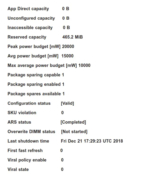
Latched Last shutdown status PM S5 Received, PMIC 12V/DDRT 1.2V Power
Loss (PLI), Controller’s FW State Flush Complete, Write Data Flush Complete, PM Idle Received
(Note: All DCPMM items and strings displayed on the BIOS screen are provided by
Intel and will depend on the driver version.)
Unlatched last shutdown status Unknown
| Security capabilities | Encryption, Erase |
| Modes supported | Memory Mode, App Direct |
| Boot status | Success |
| AIT DRAM enabled | [1] |
| Error injection enabled | [0] |
Media temperature injection enabled [0]
Software triggers enabled [0]
Software triggers enabled details None
Poison error injection counter 0
Poison error clear counter 0
Media temperature injection counter 0
Software triggers counter 0
Master Passphrase Enabled 0
- DIMM ID 0x0011
Press <Enter> and the following information regarding this DIMM will be displayed.
View settings or select an action below.
| DIMM UID | 8089-A2-1837-00000B34 |
| DIMM handle | 0x0011 |
| DIMM physical ID | 0x001B |
| Manageability state | [Manageable] |
| Health state | [Healthy] |
| Health state reason | None |
| Capacity | 252.4 GiB |
| Firmware version | 01.00.00.5127 |
| Firmware API Version | 1.11 |
| Lock state | [Disabled] |
| Staged firmware version | N/A |
| Firmware update status | Update loaded successfully |
| Manufacturer | Intel |
Show more details +
Use this feature to display or hide additional information about this DIMM. The options are Disabled and Enabled.
*If the feature, Show more details +, is set to Enabled, the following will be
displayed:
| Serial number | 0x00000B34 |
| Part number | NMA1 XBD256GQS |
| Socket | 0x0 |
| Memory controller ID | 0x0 |
| Vendor ID | Ox8089 |
| Device ID | 0x5141 |
| Subsystem vendor ID | Ox8089 |
| Subsystem device ID | Ox97A |
| Device locator | P1-DIMMB2 |
| Subsystem revision ID | 0x18 |
| Interface format code | 0x0301 (Non-Energy Backed Byte Addressable) |
| Manufacturing info valid | 1 |
| Manufacturing date | 18-37 |
| Manufacturing location | OxA2 |
| Memory type | Logical Non-Volatile Device |
| Memory bank label | PO Node° Channel1 Dimm1 |
| Data width label [b] | 64 |
| Total width [b] | 72 |
| Speed [MHz] | 2666 |
| Channel ID | Ox0001 |
| Channel position | 1 |
| Revision ID | Ox0 |
| Form factor | [DIMM] |
| Manufacturer ID | 0x8089 |
| Controller revision ID | BO (0x0020) |
| Is new | 0 |
Memory capacity 252.0 GiB
App Direct capacity 0 B
Unconfigured capacity 0 B
Inaccessible capacity 0 B
Reserved capacity 465.2 MiB
Peak power budget [mW] 20000
Avg power budget [mW] 15000
Max average power budget [mW] 10000
Package sparing capable 1
Package sparing enabled 1
Package spares available 1
Configuration status [Valid]
SKU violation 0
ARS status [Completed]
Overwrite DIMM status [Not started]
Last shutdown time Fri Dec 21 17:29:23 UTC 2018
First fast refresh 0
Viral policy enable 0
Viral state 0
Latched Last shutdown status PM S5 Received, PMIC 12V/DDRT 1.2V Power
Loss (PLI), Controller’s FW State Flush Complete, Write Data Flush Complete, PM Idle Received
(Note: All DCPMM items and strings displayed on the BIOS screen are provided by Intel and will depend on the driver version.)
Unlatched last shutdown status Unknown Security capabilities Encryption, Erase Modes supported Memory Mode, App Direct Boot status SuccessAIT DRAM enabled [1]
Error injection enabled [0]
Media temperature injection enabled [0]
Software triggers enabled [0]
Software triggers enabled details None
Poison error injection counter 0
Poison error clear counter 0
Media temperature injection counter 0
Software triggers counter 0
Master Passphrase Enabled 0
- DIMM ID 0x0111
Press <Enter> and the following information regarding this DIMM will be displayed.
View settings or select an action below.
DIMM UID 8089-A2-1837-0000110C
DIMM handle 0x0111
DIMM physical ID 0x0023
Manageability state [Manageable]
Health state [Healthy]
Health state reason None
Capacity 252.4 GiB
Firmware version 01.00.00.5127
Firmware API Version 01.11
Lock state [Disabled]
Staged firmware version N/A
Firmware update status Update loaded successfully
Manufacturer Intel
Show more details +
Use this feature to display or hide additional information about this DIMM. The options are Disabled and Enabled.
*If the feature, Show more details +, is set to Enabled, the following will be displayed:
Serial number 0x000011C
Part number NMA1XBD256GQS
Socket 0x0
Memory controller ID 0x1
Vendor ID 0x8089
Device ID 0x5141
Subsystem vendor ID 0x8089
Subsystem device ID 0x97A
Device locator P1-DIMME2
Subsystem revision ID 0x18
Interface format code 0x0301 (Non-Energy Backed Byte Addressable)
Manufacturing info valid 1
Manufacturing date 18-37
Manufacturing location 0xA2
Memory type Logical Non-Volatile Device
Memory bank label P0_Node1_Channel1_Dimm1
Data width label [b] 64
Total width [b] 72
Speed [MHz] 2666
Channel ID 0x0001
Channel position 1
Revision ID 0x0
Form factor [DIMM]
Manufacturer ID 0x8089
Controller revision ID B0 (0x0020)
Is new 0
Memory capacity 252.0 GiB
App Direct capacity 0 B
Unconfigured capacity 0 B
Inaccessible capacity 0 B
Reserved capacity 465.2 MiB
Peak power budget [mW] 20000
Avg power budget [mW] 15000
Max average power budget [mW] 10000
Package sparing capable 1
Package sparing enabled 1
Package spares available 1
Configuration status [Valid]
SKU violation 0
ARS status [Completed]
Overwrite DIMM status [Not started]
Last shutdown time Fri Dec 21 17:29:23 UTC 2018
First fast refresh 0
Viral policy enable 0
Viral state 0
Latched Last shutdown status PM S5 Received, PMIC 12V/DDRT 1.2V Power Loss (PLI), Controller’s FW State Flush Complete, Write Data Flush Complete,
PM Idle Received
(Note: All DCPMM items and strings displayed on the BIOS screen are provided by Intel and will depend on the driver version.)Unlatched last shutdown status Unknown
Error injection enabled [0]
Media temperature injection enabled [0]
Software triggers enabled [0]
Software triggers enabled details None
Poison error injection counter 0
Poison error clear counter 0
Media temperature injection counter 0
Software triggers counter 0
Master Passphrase Enabled 0
- DIMM ID 0x0021
Press <Enter> and the following information regarding this DIMM will be displayed.
View settings or select an action below.
DIMM UID 8089-A2-1837-00000B2E
DIMM handle 0x0021
DIMM physical ID 0x001D
Manageability state [Manageable]
Health state [Healthy]
Health state reason None
Capacity 252.4 GiB
Firmware version 01.00.00.5127
Firmware API Version 01.11
Lock state [Disabled]
Staged firmware version N/A
Firmware update status Update loaded successfully
Manufacturer Intel
Show more details +
Use this feature to display or hide additional information about this DIMM. The options are Disabled and Enabled.
*If the feature, Show more details +, is set to Enable, the following will be displayed:
Serial number 0x00000B2E
Part number NMA1XBD256GQS
Socket 0x0
Memory controller ID 0x0
Vendor ID 0x8089
Device ID 0x5141
Subsystem vendor ID 0x8089
Subsystem device ID 0x97A
Device locator P1-DIMMC2
Subsystem revision ID 0x18
Interface format code 0x0301 (Non-Energy Backed Byte Addressable)
Manufacturing info valid 1
Manufacturing date 18-37
Manufacturing location 0xA2
Memory type Logical Non-Volatile Device
Memory bank label P0_Node0_Channel2_Dimm1
Data width label [b] 64
Total width [b] 72
Speed [MHz] 2666
Channel ID 0x0002
Channel position 1
Revision ID 0x0
Form factor [DIMM]
Manufacturer ID 0x8089
Controller revision ID B0 (0x0020)
Is new 0
Memory capacity 252.0 GiB
App Direct capacity 0 B
Unconfigured capacity 0 B
Inaccessible capacity 0 B
Reserved capacity 465.2 MiB
Peak power budget [mW] 20000
Avg power budget [mW] 15000
Max average power budget [mW] 10000
Package sparing capable 1
Package sparing enabled 1
Package spares available 1
Configuration status [Valid]
SKU violation 0
ARS status [Completed]
Overwrite DIMM status [Not started]
Last shutdown time Fri Dec 21 17:29:23 UTC 2018
First fast refresh 0
Viral policy enable 0
Viral state 0
Latched Last shutdown status PM S5 Received, PMIC 12V/DDRT 1.2V Power
Loss (PLI), Controller’s FW State Flush Complete, Write Data Flush Complete, PM Idle Received
(Note: All DCPMM items and strings displayed on the BIOS screen are provided by Intel and will depend on the driver version.)
Unlatched last shutdown status Unknown
Security capabilities Encryption, Erase
Modes supported Memory Mode, App Direct
Boot status Success
AIT DRAM enabled [1]
Error injection enabled [0]
Media temperature injection enabled [0]
Software triggers enabled [0]
Software triggers enabled details None
Poison error injection counter 0
Poison error clear counter 0
Media temperature injection counter 0
Software triggers counter 0
Master Passphrase Enabled 0
- DIMM ID 0x0121
Press <Enter> and the following information regarding this DIMM will be displayed.
View settings or select an action below.
DIMM UID 8089-A2-1837-000010AE
DIMM handle 0x0121
DIMM physical ID 0x0025
Manageability state [Manageable]
Health state [Healthy]
Health state reason None
Capacity 252.4 GiB
Firmware version 01.00.00.5127
Firmware API Version 01.11
Lock state [Disabled]
Staged firmware version N/A
Firmware update status Update loaded successfully
Manufacturer Intel
Show more details +
Use this feature to display or hide additional information about this DIMM. The options are Disabled and Enabled.
*If the feature, Show more details +, is set to Enable, the following will be displayed:
Serial number 0x000010AE
Part number NMA1XBD256GQS
Socket 0x0
Memory controller ID 0x0
Vendor ID 0x8089
Device ID 0x5141
Subsystem vendor ID 0x8089
Subsystem device ID 0x97A
Device locator P1-DIMMF2
Subsystem revision ID 0x18
Interface format code 0x0301 (Non-Energy Backed Byte Addressable)
Manufacturing info valid 1
Manufacturing date 18-37
Manufacturing location 0xA2
Memory type Logical Non-Volatile Device
Memory bank label P0_Node1_Channel2_Dimm1
Data width label [b] 64
Total width [b] 72
Speed [MHz] 2666
Channel ID 0x0002
Channel position 1
Revision ID 0x0
Form factor [DIMM]
Manufacturer ID 0x8089
Controller revision ID B0 (0x0020)
Is new 0
Memory capacity 252.0 GiB
App Direct capacity 0 B
Unconfigured capacity 0 B
Inaccessible capacity 0 B
Reserved capacity 465.2 MiB
Peak power budget [mW] 20000
Avg power budget [mW] 15000
Max average power budget [mW] 10000
Package sparing capable 1
Package sparing enabled 1
Package spares available 1
Configuration status [Valid]
SKU violation 0
ARS status [Completed]
Overwrite DIMM status [Not started]
Last shutdown time Fri Dec 21 17:29:23 UTC 2018
First fast refresh 0
Viral policy enable 0
Viral state 0
Latched Last shutdown status PM S5 Received, PMIC 12V/DDRT 1.2V Power
Loss (PLI), Controller’s FW State Flush Complete, Write Data Flush Complete, PM Idle Received
(Note: All DCPMM items and strings displayed on the BIOS screen are provided by Intel and will depend on the driver version.)
Unlatched last shutdown status Unknown Security capabilities Encryption, Erase Modes supported Memory Mode, App Direct
Boot status Success
AIT DRAM enabled [1]
Error injection enabled [0]
Media temperature injection enabled [0]
Software triggers enabled [0]
Software triggers enabled details None
Poison error injection counter 0
Poison error clear counter 0
Media temperature injection counter 0
Software triggers counter 0
Master Passphrase Enabled 0
- Monitor health
Current non-critical threshold status
Controller temperature: within the non-critical threshold on all DIMMs.
Media temperature: within the non-critical threshold on all DIMMs.
Percentage remaining: within the non-critical threshold on all DIMMs.
Modify non-critical thresholds
Controller temperature [C]
Use this feature to set controller temperature in Celsius. (Min. = 20°C, Max. = 105°C)
Media temperature [C]
Use this feature to set media temperature in Celsius. (Min = 20°C, Max = 85°C )
Percentage remaining [%]
Use this feature to set spare capacity as a percentage. (Min = 1%, Max = 99%) - Apply changes
- Back to main menu
- Update firmware
Specify the firmware image to load on the DIMMs on the next system restart and select Update.
Current firmware version: 01.00.00.5127
Selected firmware version: None
File:
Press <Enter> and type in the file path relative to the root directory of the device containing the new firmware image file, such as “\firmware\newFirmware.bin”. Staged firmware version: N/A
- Update
- Back to main menu
- Configure security
Specify the security settings on ALL the DIMMs.
State: [Disabled]
[Disabled, Frozen] will be displayed after pressing the following feature, Frozen lock.
Enable security
Use this feature to enable security by entering a new passphrase. Press <Enter> to type in a new passphrase with at least one character.
Secure erase
Use this feature to erase all persistent data. The options are Yes and No
Frozen lock
Use this feature to prevent further lock state changes until the next reboot. - Back to main menu
- Configure data policy
Specify the data policy settings on ALL the DIMMs.
First fast refresh state: [Disabled] (or [Enabled])
Depending on the settings of the following feature, Enable/Disable first fast refresh,
[Disabled] or [Enabled] will be displayed. - Enable/Disable first fast refresh
Use this feature to enable/disable the feature above, First fast refresh state. - Back to main menu
- Back to main menu
- Regions
Use this submenu to configure and display regions.
Current configuration
There are no regions defined in the system.
Memory allocation goal configuration
No goal configuration specified. - Create goal config
Use this submenu to create goal configuration of DIMM regions.
Select the scope of the new region then set the desired sizes.
Create goal config for:
Use this feature to select a target to create a goal configuration. The options are Platform and Socket.
Reserved [%]:
Enter a value (0-100) to reserve a percentage of the requested DIMM capacity that will not be mapped into the system’s physical address space.
Memory Mode [%]:
Enter a value (0-100) to set the percentage of the total capacity to use in Memory Mode.
Persistent memory type:
Use this feature to select the type of persistent memory capacity to create. The options are App
Direct and App Direct Not interleaved.
Namespace Label version:
While creating goals, use this feature to display and modify the namespace label version to initialize. The options are 1.2 and 1.1. - Create goal config
Use this feature to create goal configuration on the selected target. - Back to Regions menu
- Back to main menu
- Back to main menu
Namespaces
Use this submenu to display, create, modify, and delete namespaces.
Select a namespace to view more information.
NamespaceID Name Health Status.
0x00000101 Healthy
Use this feature to display details for or modify selected namespace.
View details for or modify selected namespace.
UUID 66B9E696-0E38-47B3-81
5E-99FFAFC26A23
ID 0x00000101
Name
Press <Enter> to type in a name of namespace.
Region 1
Health [Healthy]
Mode [None]
Block size [4096 B]
Units
Use this feature to change the units of the input namespace capacity. The options are
B, MB, MiB, GB, GiB, TB, and TiB.
Capacity 125.0
Label version 1.2 - Save
Use this feature to save current namespace. - Delete Use this feature to delete current namespace.
- Back to Namespaces
- Back to main menu
- Create namespace Name Press <Enter> to type in a name of namespace. Region ID This feature displays the region ID on which to create a namespace. Mode Use this feature to set namespace mode. The options are None and Sector. The option, None, is for raw access only. Set this feature to Sector to guarantee powerful write atomicity via a block translation table (BTT) Capacity input The options are Remaining and Manual. Set this feature to Remain to use the maximum available capacity. Set this feature to Manual to enter the capacity manually. Units Use this feature to change the units of the input namespace capacity. The options are B, MB, MiB, GB, GiB, TB, and TiB. Capacity This feature displays the capacity of the namespace.
- Create a namespace Press <Enter> to create a namespace with the above configuration.
- Back to Namespace
- Back to main menu
- Back to main menu (return to the main menu.)
- Total capacity
The following information is displayed.
Total DCPMM resource allocation across the host server.
Raw capacity: 1.45 TiB
App Direct capacity: 0 B
Memory capacity: 1.45 TiB
Unconfigured capacity: 0 TiB
Inaccessible capacity: 0 TiB
Reserved capacity: 2.7 GiB - Back to main menu
- Diagnostics
Perform diagnostic tests on DIMMS.
Choose diagnostics type:
Quick diagnostics
Select Enabled to perform quick diagnostics test. The options are Disabled and Enabled.
DIMM ID 0x0001
Select Enabled to enable the diagnostics procedure for this DIMM. The options are Disabled and Enabled.
DIMM ID 0x0101
Select Enabled to enable the diagnostics procedure for this DIMM. The options are Disabled and Enabled.
DIMM ID 0x0011
Select Enabled to enable the diagnostics procedure for this DIMM. The options are Disabled and Enabled.
DIMM ID 0x0111
Select Enabled to enable the diagnostics procedure for this DIMM. The options are Disabled and Enabled.
DIMM ID 0x0021
Select Enabled to enable the diagnostics procedure for this DIMM. The options are Disabled and Enabled.
DIMM ID 0x0121
Select Enabled to enable the diagnostics procedure for this DIMM. The options are Disabled and Enabled.
Config diagnostics
Select Enabled to enable the platform configuration diagnostics test. The options are
Disabled and Enabled.
FW diagnostics
Select Enabled to enable the firmware diagnostics test. The options are Disabled and Enabled.
Security diagnostics
Select Enabled to enable the security diagnostics test. The options are Disabled and Enabled. - Execute tests (execute selected diagnostic tests)
Press <Enter> to perform the selected diagnostic tests. The following information is displayed. - Back to Diagnostics
- Back to main menu
TestName: Quick
State: Ok
Message:
The quick health check succeeded.
TestName: Config
State: Ok
Message:
The platform configuration check succeeded.
TestName: Security
State: Ok
Message:
The security check succeeded.
TestName: FW
State: Ok
Message:
The firmware consistency and settings check succeeded. - Back to main menu
- Preferences
Use this submenu to display and/or modify user preferences.
View and/or modify user preferences.
Default DIMM ID:
Use this feature to view and/or modify the default display of DIMM identifiers. The options are Handle and UID.
Capacity units:
This feature is to view and/or modify the default units for displaying capacities. Use auto (x1024) or Auto_10 (x1000) to automatically select the best format. The options are Auto, Auto_10, B, MB, MiB, GB, GiB, TB, and TiB .
App Direct settings:
This feature is to view and/or modify the interleaving settings for creating App Direct capacity. The default setting is 4KB_4KB (Recommended).
App Direct granularity:
This feature is to view and/or modify the minimum App Direct granularity per DIMM. The options are Recommended and 1. - Back to main menu
- Driver Health
This submenu displays the health status of the drivers and controllers as detected by the system. The following information is displayed. - Intel(R) DCPMM 1.0.0.3380 Driver Healthy
Intel(R) DCPMM Controller Healthy
Intel Persistent Memory DIMM 25 Controller Healthy
Intel Persistent Memory DIMM 33 Controller Healthy
Intel Persistent Memory DIMM 27 Controller Healthy
Intel Persistent Memory DIMM 35 Controller Healthy
Intel Persistent Memory DIMM 29 Controller Healthy
Intel Persistent Memory DIMM 37 Controller Healthy
- Intel(R) DCPMM 1.0.0.3380 HII Driver Healthy
Controller 665c5c98 Child 0 Healthy
6.4 Event Logs
Use this feature to configure Event Log settings.
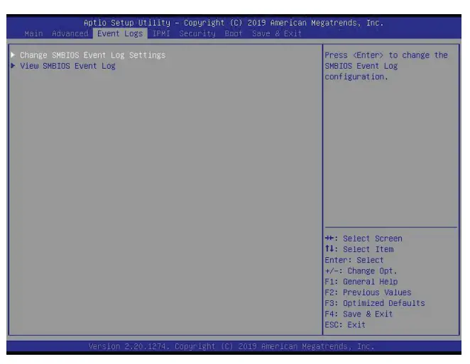
- Change SMBIOS Event Log Settings
Enabling/Disabling Options
SMBIOS Event Log
Change this feature to enable or disable all features of the SMBIOS Event Logging during system boot. The options are Enabled and Disabled.
Erasing Settings
Erase Event Log
If No is selected, data stored in the event log will not be erased. Select Yes, Next Reset, data in the event log will be erased upon next system reboot. Select Yes, Every Reset, data in the event log will be erased upon every system reboot. The options are No, Yes, Next reset, and Yes, Every reset.
When Log is Full
Select Erase Immediately for all messages to be automatically erased from the event log when the event log memory is full. The options are Do Nothing and Erase Immediately.
SMBIOS Event Log Standard Settings
Log System Boot Event
This feature toggles the System Boot Event logging to enabled or disabled. The options are Disabled and Enabled.
MECI
The Multiple Event Count Increment (MECI) counter counts the number of occurrences that a duplicate event must happen before the MECI counter is incremented. This is a numeric value. The default value is 1.
METW
The Multiple Event Time Window (METW) defines the number of minutes that must pass between duplicate log events before MECI is incremented. This is in minutes, from 0 to 99. The default value is 60.
Note: All values changed here do not take effect until computer is restarted. - View SMBIOS Event Log
Select this submenu and press enter to see the contents of the SMBIOS event log. The following categories will be displayed: Date/Time/Error Codes/Severity.
6.5 IPMI
Use this feature to configure Intelligent Platform Management Interface (IPMI) settings.
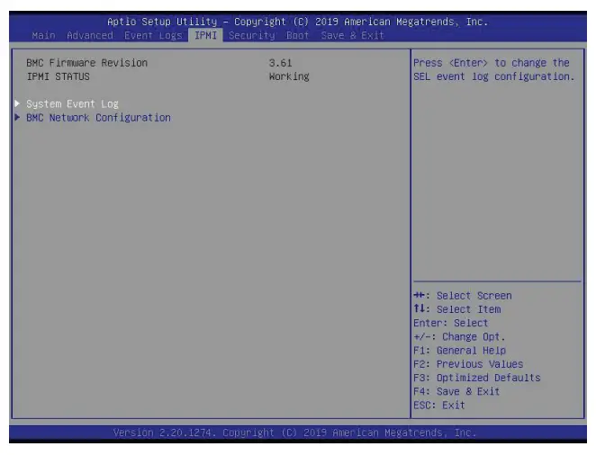
BMC Firmware Revision
This feature indicates the IPMI firmware revision used in your system.
IPMI Status (Baseboard Management Controller)
This feature indicates the status of the IPMI firmware installed in your system.
- System Event Log
Enabling/Disabling Options
SEL Components
Select Enabled for all system event logging at bootup. The options are Enabled and Disabled.
Erasing Settings
Erase SEL
Select Yes, On next reset to erase all system event logs upon next system reboot. Select Yes, On every reset to erase all system event logs upon each system reboot. Select No to keep all system event logs after each system reboot. The options are No, Yes, On next reset, and Yes, On every reset.
When SEL is Full
This feature allows the user to decide what the BIOS should do when the system event log is full. Select Erase Immediately to erase all events in the log when the system event log is full. The options are Do Nothing and Erase Immediately.
Note: All values changed here do not take effect until computer is restarted.
- BMC Network Configuration
BMC Network Configuration
Update IPMI LAN Configuration
Select Yes for the BIOS to implement all IP/MAC address changes at the next system boot.
The options are No and Yes.
Configure IPv4 Support
This section displays configuration features for IPv4 support.
IPMI LAN Selection
This feature displays the IPMI LAN setting. The default setting is Failover.
IPMI Network Link Status
This feature displays the IPMI Network Link status. The default setting is Dedicated LAN.
*If the feature above is set to Yes, the following feature will become available for configuration:
Configuration Address Source
This feature allows the user to select the source of the IP address for this computer. If Static is selected, you will need to know the IP address of this computer and enter it to the system manually in the field. If DHCP is selected, the BIOS will search for a DHCP (Dynamic Host Configuration Protocol) server in the network that is attached to and request the next available IP address for this computer. The options are DHCP and Static.
*If the feature above is set to Static, the following features will become available for configuration:
Station IP Address
This feature displays the Station IP address for this computer. This should be in decimal and in dotted quad form (i.e., 192.168.10.253).
Subnet Mask
This feature displays the sub-network that this computer belongs to. The value of each three-digit number separated by dots should not exceed 255.
Station MAC Address
This feature displays the Station MAC address for this computer. Mac addresses are six two-digit hexadecimal numbers.
Gateway IP Address
This feature displays the Gateway IP address for this computer. This should be in decimal and in dotted quad form (i.e., 172.31.0.1).
VLAN
This feature displays the virtual LAN settings. The options are Disable and Enable.
Configure IPv6 Support
This section displays configuration features for IPv6 support.
LAN Channel 1
IPv6 Support
Use this feature to enable IPv6 support. The options are Enabled and Disabled.
Configuration Address Source
This feature allows the user to select the source of the IP address for this computer. If Static is selected, you will need to know the IP address of this computer and enter it to the system manually in the field. If DHCP is selected, the BIOS will search for a DHCP (Dynamic Host Configuration Protocol) server in the network that is attached to and request the next available IP address for this computer. The options are Static and DHCP.
*If the feature above is set to Static, the following features will become available for
configuration:
• Station IPv6 Address
• Prefix Length
• IPv6 Router1 IP Address
6.6 Security
This menu allows the user to configure the following security settings for the system.
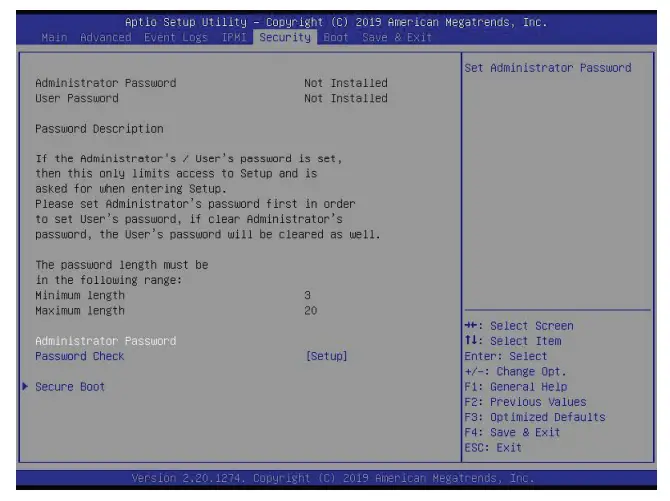
Administrator Password
Press Enter to create a new, or change an existing, Administrator password.
User Password
Press Enter to create a new, or change an existing, User password.
Password Check
Select Setup for the system to check for a password at Setup. Select Always for the system to check for a password at bootup or upon entering the BIOS Setup utility. The options are Setup and Always.
- Secure Boot
This section displays the contents of the following secure boot features:
• System Mode
• Vendor Keys
• Secure Boot
Secure Boot
Use this feature to enable secure boot. The options are Disabled and Enabled.
Secure Boot Mode
Use this feature to configure Secure Boot variables without authentication. The options are Standard and Custom.
CSM Support
Select Enabled to support the EFI Compatibility Support Module (CSM), which provides compatibility support for traditional legacy BIOS for system boot. The options are Enabled and Disabled. - Key Management
This submenu allows the user to configure the following Key Management settings.
Provision Factory Default Keys
Select Enabled to install the default Secure Boot keys set by the manufacturer. The options are Disabled and
Enabled. - Restore Factory Keys
Select Yes to install factory default Secure Boot keys set by the manufacturer. The options are Yes and
No. - Reset to Setup Mode
Select Yes to delete all variables and reset the System to Setup Mode. The options are
Yes and No. - Export Secure Boot variables
This feature allows the user to export Secure Boot variables to a folder in the system. - Enroll Efi Image
This feature allows the image to run in Secure Boot Mode. Enroll SHA256 Hash Certificate of the image into the Authorized Signature
Database.
Device Guard Ready - Remove ‘UEFI CA’ from DB
This feature allows the user to remove ‘UEFI CA certificate from an authorized signature database. The options are Yes and No. - Restore DB defaults
This feature allows the user to restore DB variables to factory default. The options are
Yes and No.
Secure Boot Variables
This feature allows the user to decide if all secure boot variables should be saved. - Platform Key (PK)
This feature allows the user to configure the settings of the platform keys. The options are Details, Export, Update, and Delete.
Update
Select Yes to load the new platform keys (PK) from the manufacturer’s defaults. Select
No loading the platform keys from a file. The options are Yes and No. - Key Exchange Keys
Update
Select Yes to load the KEK from the manufacturer’s defaults. Select No to load the KEK from a file. The options are Yes and No.
Append
Select Yes to add the KEK from the manufacturer’s defaults list to the existing KEK.
Select No to load the KEK from a file. The options are Yes and No. - Authorized Signatures
Update
Select Yes to load the database from the manufacturer’s defaults. Select No to load the DB from a file. The options are Yes and No.
Append
Select Yes to add the database from the manufacturer’s defaults to the existing DB.
Select No to load the DB from a file. The options are Yes and No. - Forbidden Signatures
Update
Select Yes to load the DBX from the manufacturer’s defaults. Select No to load the DBX from a file. The options are Yes and No.
Append
Select Yes to add the DBX from the manufacturer’s defaults to the existing DBX. Select
No to load the DBX from a file. The options are Yes and No. - Authorized TimeStamps
Update
Select Yes to load the DBT from the manufacturer’s defaults. Select No to load the DBT from a file. The options are Yes and No.
Append
Select Yes to add the DBT from the manufacturer’s defaults list to the existing DBT. Select
No to load the DBT from a file. The options are Yes and No. - OsRecovery Signatures
This feature uploads and installs an OSRecovery Signature. You may insert a factory
default key or load from a file. The file formats accepted are:
1) Public Key Certificate
a. EFI Signature List
b. EFI CERT X509 (DER Encoded)
c. EFI CERT RSA2048 (bin)
d. EFI SERT SHA256 (bin)
2) EFI Time-Based Authenticated Variable
When prompted, select “Yes” to load Factory Defaults or “No’ to load from a file.
Update
Select Yes to load the DBR from the manufacturer’s defaults. Select No to load the DBR from a file. The options are Yes and No.
Append
This feature uploads and adds an OSRecovery Signature into the Key Management. You may insert a factory default key or load from a file. When prompted, select “Yes” to load Factory Defaults or “No’ to load from a file.
6.7 Boot
Use this feature to configure Boot settings.
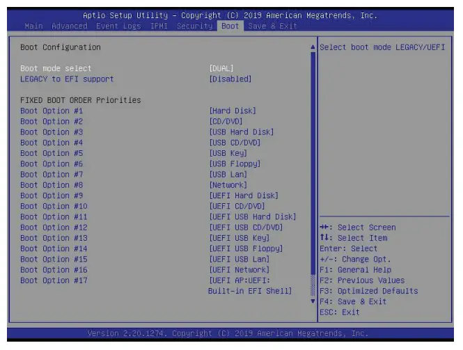
Boot Mode Select
Use this feature to select the type of device that the system is going to boot from. The options are Legacy, UEFI, and Dual.
Legacy to EFI Support
Select Enabled to boot EFI OS support after Legacy boot order has failed. The options are Disabled and Enabled.
FIXED BOOT ORDER Priorities
This feature prioritizes the order of bootable devices that the system boots from. Press
<Enter> on each entry from top to bottom to select devices.
*If the feature “Boot Mode Select” above is set to Legacy, UEFI, or Dual, the following features will be displayed:
- Boot Option #1
- Boot Option #2
- Boot Option #3
- Boot Option #4
- Boot Option #5
- Boot Option #6
- Boot Option #7
- Boot Option #8
- Boot Option #9
- Boot Option #10
- Boot Option #11
- Boot Option #12
- Boot Option #13
- Boot Option #14
- Boot Option #15
- Boot Option #16
- Boot Option #17
- Add New Boot Option
This feature allows the user to add a new boot option to the boot priority features for your system.
Add Boot Option
Use this feature to specify the name for the new boot option.
Path for Boot Option
Use this feature to enter the path for the new boot option in the format fsx:\path\filename.efi.
Boot Option File Path
Use this feature to specify the file path for the new boot option.
Create
Use this feature to set the name and the file path of the new boot option. - Delete Boot Option
This feature allows the user to select a boot device to delete from the boot priority list.
Delete Boot Option
Use this feature to remove an EFI boot option from the boot priority list. The options are
Select one to Delete and UEFI: Built-in EFI Shell. - UEFI Application Boot Priorities
This feature sets the system boot order of detected devices. The options are UEFI: Builtin EFI Shell and Disabled.
• Boot Option #1 - UEFI USB Key Drive BBS Priorities
This feature sets the system boot order of detected devices.
• Boot Option #1 - USB Key Drive BBS Priorities
This feature sets the system boot order of detected devices.
• Boot Option #1 - NETWORK Drive BBS Priorities
This feature sets the system boot order of detected devices.
• Boot Option #1
6.8 Save & Exit
Select the Save & Exit tab from the BIOS setup screen to configure the settings below:
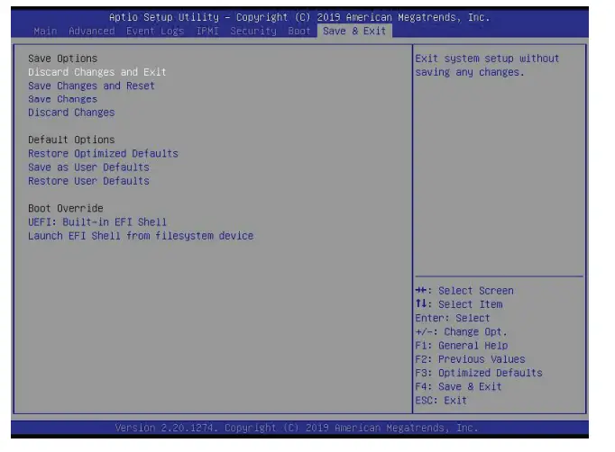
Save Options
Discard Changes and Exit
Select this feature to quit the BIOS Setup without making any permanent changes to the system configuration, and reboot the computer. Select Discard Changes and Exit from the Save & Exit menu and press <Enter>.
Save Changes and Reset
After completing the system configuration changes, select this feature to save the changes you have made. This will not reset (reboot) the system.
Save Changes
When you have completed the system configuration changes, select this feature to leave the BIOS setup utility and reboot the computer for the new system configuration parameters to take effect. Select Save Changes from the Save & Exit menu and press <Enter>.
Discard Changes
Select this feature and press <Enter> to discard all the changes and return to the AMI BIOS utility program.
Default Options
Restore Optimized Defaults
To set this feature, select Restore Defaults from the Save & Exit menu and press <Enter>.
These are factory settings designed for maximum system stability, but not for maximum performance.
Save As User Defaults
To set this feature, select Save as User Defaults from the Save & Exit menu and press <Enter>. This enables the user to save any changes to the BIOS setup for future use.
Restore User Defaults
To set this feature, select Restore User Defaults from the Save & Exit menu and press <Enter>.
Use this feature to retrieve user-defined settings that were saved previously.
Boot Override
Listed in this section are other boot options for the system (i.e., Built-in EFI shell). Select an option and press <Enter>. Your system will boot to the selected boot option.
Appendix A
BIOS Error Codes
A.1 BIOS Error Beep (POST) Codes
During the POST (Power-On Self-Test) routines, which are performed each time the system is powered on, errors may occur.
Non-fatal errors are those which, in most cases, allow the system to continue the boot-up process. The error messages normally appear on the screen.
Fatal errors are those which will not allow the system to continue the boot-up procedure. If a fatal error occurs, you should consult with your system manufacturer for possible repairs. These fatal errors are usually communicated through a series of audible beeps. The table below lists some common errors and their corresponding beep codes encountered by users.
| BIOS Beep (POST) Codes | ||
| Beep Code | Error Message | Description |
| 1 beep | Refresh | Circuits have been reset (Ready to power up) |
| 5 short, 1 long | Memory error | No memory detected in system |
| 5 long, 2 short | Display memory read/write error | Video adapter missing or with faulty memory |
| 1 long continuous | System OH | System overheat condition |
A.2 Additional BIOS POST Codes
The AMI BIOS supplies additional checkpoint codes, which are documented online at http://www.supermicro.com/support/manuals/ (“AMI BIOS POST Codes User’s Guide”).
When BIOS performs the Power On Self Test, it writes checkpoint codes to I/O port 0080h. If the computer cannot complete the boot process, a diagnostic card can be attached to the computer to read I/O port 0080h (Supermicro p/n AOC-LPC80-20). For information on AMI updates, please refer to http://www.ami.com/products/.
Appendix B
Standardized Warning Statements for AC
Systems
B.1 About Standardized Warning Statements
The following statements are industry standard warnings, provided to warn the user of situations which have the potential for bodily injury. Should you have questions or experience difficulty, contact Supermicro’s Technical Support department for assistance. Only certified technicians should attempt to install or configure components.
Read this appendix in its entirety before installing or configuring components in the Supermicro chassis.
These warnings may also be found on our website at http://www.supermicro.com/about/policies/safety_information.cfm.
Warning Definition![]() Warning! This warning symbol means danger. You are in a situation that could cause bodily injury. Before you work on any equipment, be aware of the hazards involved with electrical circuitry and be familiar with standard practices for preventing accidents.
Warning! This warning symbol means danger. You are in a situation that could cause bodily injury. Before you work on any equipment, be aware of the hazards involved with electrical circuitry and be familiar with standard practices for preventing accidents.
Appendix C
System Specifications
Processors
Supports single 2 nds Gen/1 st Gen Intel Xeon® Scalable-SP series and Intel Xeon® W-32XX series processors, up to 28 cores and 205W TDP Note: Please refer to the motherboard specifications pages on our website for updates to supported processors.
Chipset
Intel PCH C621 BIOS 256 Mb AMI BIOS SPI Flash BIOS ACPI 6.0, Plug and Play (PnP), BIOS rescue hot-key, riser card auto detection support, and SMBIOS 3.0 or later
Memory
Supports up to 12x 1.2V DDR4 ECC RDIMM/3DS RDIMM/LRDIMM3DS LRDIMM, up to 2933MHz and maximum capacity up to 3TB via 3DS RDIMM/3DS LRDIMM
SATA Controller
On-chip (Intel PCH C621) controller
Drive Bays
Eight hot-swap external 3.5″ SATA/SAS drives via the backplane, supports RAID 0, 1, 5, 10
Four M.2 sockets with heatsink (M-key PCI-E 3.0 x4 in the 2260/2280/22110 form factor. Supports RAID 0 on four sockets.
Supports VROC on one socket.)
Expansion Slots
Three 5.25″ external peripheral bays
One 3.5″ external peripheral bays
Four PCI-E 3.0 x16 slots (CPU SLOT1, 3, 5, 7) and three PCI-E 3.0 x8 slots (INx16) (CPU SLOT2, 4, 6) (supports seven single-width or four double-width GPU cards)
Motherboard
X11SPA-T 13 x 12 in. / 330 x 305 mm. (W x L)
Chassis
SC747BTS-R2K20BP; 4U Tower or Rackmount, 7.0 x 18.2 x 26.5 in. / 178 x 462 x 673 mm. (W x H x D)
System Cooling
Two 9-cm 7.5K RPM hot-swap lower-middle fans
Two 9-cm PWM hot-swap upper-middle fans
Two 8-cm PWM hot-swap rear fans
Two 8-cm 8.2K RPM hot-swap rear fans (optional)
Power Supply
Model: PWS-2K20A-1R
AC Input Voltages: 100-240 Vac
Rated Input Current: 14A (100V) to 11A (240 V)
Rated Input Frequency: 50-60 Hz
Rated Output Power: 2200W
Rated Output Voltages: +12V (183.3A), +5Vsb (6A)
Operating Environment
Operating Temperature: 10º to 35º C (50º to 95º F)
Non-operating Temperature: -40º to 60º C (-40º to 140º F)
Operating Relative Humidity: 8% to 90% (non-condensing)
Non-operating Relative Humidity: 5% to 95% (non-condensing)
Regulatory Compliance
Electromagnetic Emissions: FCC Class A, EN 55032 Class A, EN 61000-3-2/3-3, CISPR 32 Class A
Electromagnetic Immunity: EN 55024/CISPR 24, (EN 61000-4-2, EN 61000-4-3, EN 61000-4-4, EN 61000-4-5, EN 61000-4-6,
EN 61000-4-8, EN 61000-4-11)
Safety: CSA/EN/IEC/UL 60950-1 Compliant, UL or CSA Listed (USA and Canada), CE Marking (Europe)
Other: VCCI-CISPR 32 and AS/NZS CISPR 32
Environmental: Directive 2011/65/EU, Delegated Directive (EU) 2015/863, and Directive 2012/19/EU
Perchlorate Warning
California Best Management Practices Regulations for Perchlorate Materials: This Perchlorate warning applies only to products
containing CR (Manganese Dioxide) Lithium coin cells. “Perchlorate Material-special handling may apply. See www.dtsc.ca.gov/hazardouswaste/perchlorate”
Appendix D
UEFI BIOS Recovery
Warning: Do not upgrade the BIOS unless your system has a BIOS-related issue. Flashing the wrong BIOS can cause irreparable damage to the system. In no event shall Supermicro be liable for direct, indirect, special, incidental, or consequential damages arising from a BIOS update. If you need to update the BIOS, do not shut down or reset the system while the BIOS is updating to avoid possible boot failure.
D.1 Overview
The Unified Extensible Firmware Interface (UEFI) provides a software-based interface between the operating system and the platform firmware in the pre-boot environment. The UEFI specification supports an architecture-independent mechanism that will allow the UEFI OS loader stored in an add-on card to boot the system. The UEFI offers clean, hands-off management to a computer during system boot.
D.2 Recovering the UEFI BIOS Image
A UEFI BIOS flash chip consists of a recovery BIOS block and the main BIOS block (the main BIOS image). The recovery block contains critical BIOS codes, including memory detection and recovery codes for the user to flash a healthy BIOS image if the original main BIOS image is corrupted. When the system power is turned on, the recovery block codes execute first. Once this process is complete, the main BIOS code will continue with system initialization and the remaining POST (Power-On Self-Test) routines. Note 1: Follow the BIOS recovery instructions below for BIOS recovery when the main BIOS block crashes. Note 2: When the BIOS recovery block crashes, you will need to follow the procedures to make a Returned Merchandise Authorization (RMA) request. Also, you may use the Supermicro Update Manager (SUM) Out-of-Band (OOB) (https://www.supermicro.com.tw/products/nfo/SMS_SUM.cfm) to reflash the BIOS.
D.3 Recovering the BIOS Block with a USB Device
This feature allows the user to recover the main BIOS image using a USB-attached device without additional utilities used. A USB flash device such as a USB Flash Drive, or a USB CD/DVD ROM/RW device can be used for this purpose. However, a USB Hard Disk drive cannot be used for BIOS recovery at this time.
The file system supported by the recovery block is FAT (including FAT12, FAT16, and FAT32), which is installed on a bootable or non-bootable USB-attached device. However, the BIOS might need several minutes to locate the SUPER.ROM file if the media size becomes too large due to the huge volumes of folders and files stored in the device.
To perform UEFI BIOS recovery using a USB-attached device, follow the instructions below:
- Using a different machine, copy the “Super. ROM” binary image file into the disc Root “\” directory of a USB device or a writable CD/DVD.
Note 1: If you cannot locate the “Super. ROM” file in your driver disk, visit our website at www.supermicro.com to download the BIOS package. Extract the BIOS binary image
into a USB flash device and rename it “Super. ROM” for BIOS recovery use.
Note 2: Before recovering the main BIOS image, confirm that the “Super. ROM” binary image file you download is the same version or a close version meant for your motherboard. - Insert the USB device that contains the new BIOS image (“Super. ROM”) into your USB port and reset the system until the following screen appears:

- After locating the new BIOS binary image, the system will enter the BIOS Recovery menu as shown below:
 Note: At this point, you may decide if you want to start the BIOS recovery. If you decide to proceed with BIOS recovery, follow the procedures below.
 - When the screen as shown above displays, use the arrow keys to select the item “Proceed with flash update” and press the <Enter> key. You will see the BIOS recovery
progress as shown in the screen below:
Note: Do not interrupt the BIOS flashing process until it has completed.
- After the BIOS recovery process is completed, press any key to reboot the system.

- Using a different system, extract the BIOS package into a USB flash drive.
- Press <Del> during system boot to enter the BIOS Setup utility. From the top of the toolbar, select Boot to enter the submenu. From the submenu list, select Boot Option #1 as shown below. Then, set Boot Option #1 to [UEFI AP:UEFI: Built-in EFI Shell]. Press <F4> to save the settings and exit the BIOS Setup utility.

- When the UEFI Shell prompt appears, type fs# to change the device directory path. Go to the directory that contains the BIOS package you extracted earlier from Step 6. Enter flash.nsh BIOSname.### at the prompt to start the BIOS update process.
 Note: Do not interrupt this process until the BIOS flashing is complete.
- The screen above indicates that the BIOS update process is complete. When you see the screen above, unplug the AC power cable from the power supply, clear CMOS, and
plug the AC power cable in the power supply again to power on the system.
- Press <Del> to enter the BIOS Setup utility.
- Press <F3> to load the default settings.
- After loading the default settings, press <F4> to save the settings and exit the BIOS Setup utility.
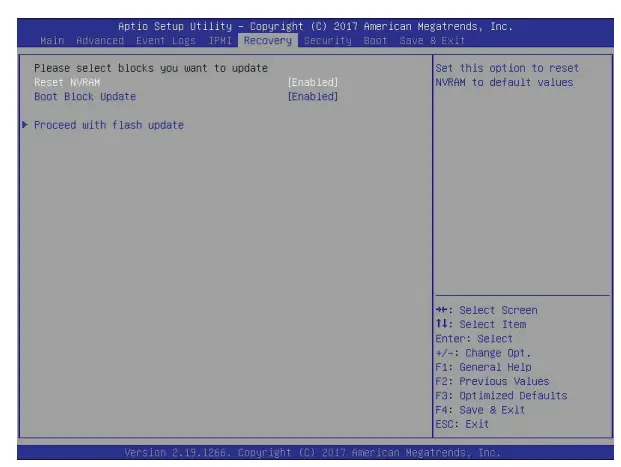 Note: At this point, you may decide if you want to start the BIOS recovery. If you decide to proceed with BIOS recovery, follow the procedures below.
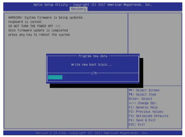
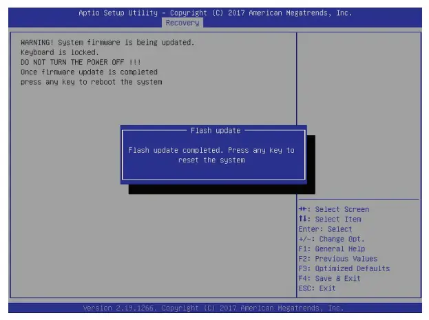
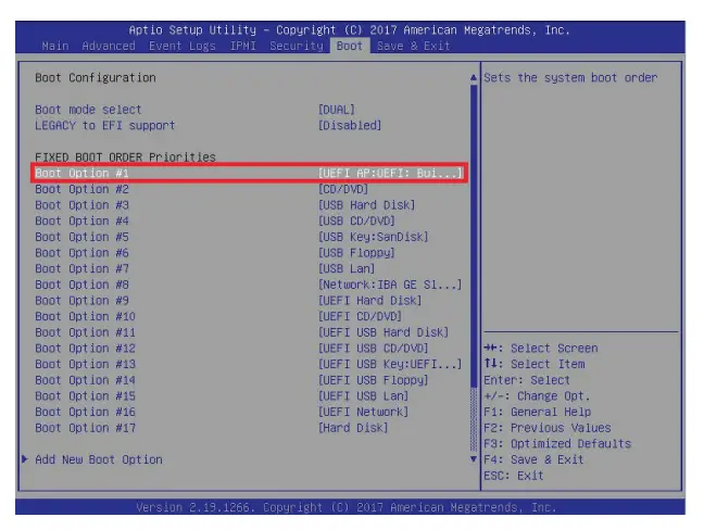
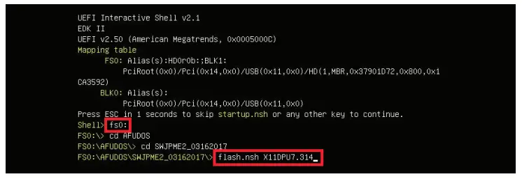 Note: Do not interrupt this process until the BIOS flashing is complete.
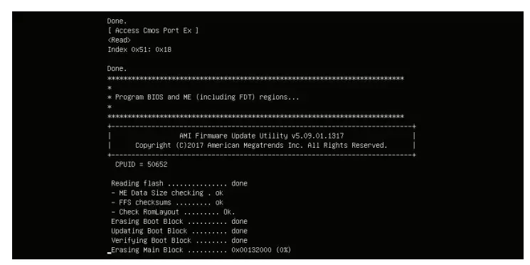
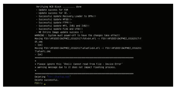
Copyright © 2019 by Super Micro Computer, Inc.
All rights reserved.
Printed in the United States of America![]()
References
 Supero - Desktop and High Performance Gaming Products | Supermicro
-
Supero - Desktop and High Performance Gaming Products | Supermicro
 dtsc.ca.gov/
-
dtsc.ca.gov/hazardouswaste/perchlorate
 P65Warnings.ca.gov
-
Supermicro Data Center Server, Blade, Data Storage, AI System
-
Supermicro Data Center Server, Blade, Data Storage, AI System
-
Supermicro Data Center Server, Blade, Data Storage, AI System
-
About Us | Supermicro
-
Safety Information | Supermicro
-
Supermicro Data Center Server, Blade, Data Storage, AI System
-
Supermicro Intelligent Management (IPMI) | Supermicro Server Management Utilities | Supermicro
-
Product Manuals | Support - Super Micro Computer, Inc.
-
Product Manuals | Support - Super Micro Computer, Inc.
-
Supermicro Data Center Server, Blade, Data Storage, AI System
-
ANDPRO.RU - интернет магазин компьютерной и офисной техники с выгодными ценами и доставкой
-
Supermicro SuperBlades, uGPU, AI System, Multi-Node Servers
-
www.supermicro.com - /wdl/driver/


