![]() INSTALLATION & OPERATION MANUAL
INSTALLATION & OPERATION MANUAL
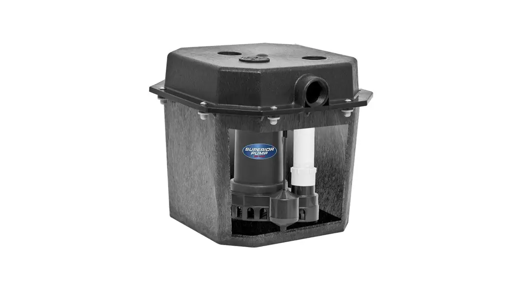
REMOTE SINK/DRAIN PUMP SYSTEM
Model: 92072-U, 92017-U, 92051-U
Safety Guidelines
Carefully read, understand and follow all safety instructions in this manual.![]() This is the safety alert symbol. When you see this symbol, look for one of the following signal words.
This is the safety alert symbol. When you see this symbol, look for one of the following signal words.![]() DANGER Indicates a hazardous situation which, if not avoided, will result in death or serious injury.
DANGER Indicates a hazardous situation which, if not avoided, will result in death or serious injury.![]() CAUTION Indicates a hazardous situation which, if not avoided, could result in death or serious injury.
CAUTION Indicates a hazardous situation which, if not avoided, could result in death or serious injury.![]() WARNING Indicates a hazardous situation which, if not avoided, could result in minor or moderate injury.
WARNING Indicates a hazardous situation which, if not avoided, could result in minor or moderate injury.
Safety Information
Read these warnings carefully. Know the application and limitations of this pump. Failure to follow these warnings could result in serious bodily injury and/or property damage.![]() DANGER RISK OF ELECTRICAL SHOCK. Disconnect and lockout power supply before removing old pump or installing or servicing this pump.
DANGER RISK OF ELECTRICAL SHOCK. Disconnect and lockout power supply before removing old pump or installing or servicing this pump.![]() DANGER RISK OF ELECTRICAL SHOCK. This pump is supplied with a grounding conductor and grounding type attachment plug. To reduce the risk of electric shock, be certain that it is connected only to a properly grounded, grounding type receptacle. For added safety, it is highly recommended to connect this pump to a GFCI (Ground Fault Circuit Interrupter) outlet. Connect only to a receptacle that is adequately rated for the voltage and amperage of this pump
DANGER RISK OF ELECTRICAL SHOCK. This pump is supplied with a grounding conductor and grounding type attachment plug. To reduce the risk of electric shock, be certain that it is connected only to a properly grounded, grounding type receptacle. For added safety, it is highly recommended to connect this pump to a GFCI (Ground Fault Circuit Interrupter) outlet. Connect only to a receptacle that is adequately rated for the voltage and amperage of this pump![]() WARNING The installation of this pump must be in accordance with the National Electric Code (NEC), Uniform Plumbing Code (UPC), International Plumbing Code (IPC) as well as all applicable local codes and ordinances.
WARNING The installation of this pump must be in accordance with the National Electric Code (NEC), Uniform Plumbing Code (UPC), International Plumbing Code (IPC) as well as all applicable local codes and ordinances.![]() CAUTION Do not install this pump in any location classified as hazardous by the National Electrical Code, ANSI/NFPA70.
CAUTION Do not install this pump in any location classified as hazardous by the National Electrical Code, ANSI/NFPA70.![]() CAUTION Do not use this pump to pump sewage or flammable or explosive fluids such as gasoline, kerosene, etc. Do not use this pump in flammable or explosive environments. Use only with liquids compatible with pump component materials.
CAUTION Do not use this pump to pump sewage or flammable or explosive fluids such as gasoline, kerosene, etc. Do not use this pump in flammable or explosive environments. Use only with liquids compatible with pump component materials.![]() WARNING RISK OF ELECTRICAL SHOCK. This pump has not been investigated for use in swimming pool or marine areas. RISK OF ELECTRICAL SHOCK. DO NOT use the power cord to remove or lower the pump into the basin. The cord may pull apart exposing bare wires which could cause a fire or electrical shock. Use the handle supplied with the pump for installing and removing the pump from the basin.
WARNING RISK OF ELECTRICAL SHOCK. This pump has not been investigated for use in swimming pool or marine areas. RISK OF ELECTRICAL SHOCK. DO NOT use the power cord to remove or lower the pump into the basin. The cord may pull apart exposing bare wires which could cause a fire or electrical shock. Use the handle supplied with the pump for installing and removing the pump from the basin.![]() WARNING Do not run the pump dry. This pump relies on water for cooling. Running the pump dry can cause the pump to overheat and the possibility of burns to anyone that handles the pump. Running the pump dry will void the warranty.
WARNING Do not run the pump dry. This pump relies on water for cooling. Running the pump dry can cause the pump to overheat and the possibility of burns to anyone that handles the pump. Running the pump dry will void the warranty.![]() WARNING Don’t expose pump to freezing temperatures. Discharge lines exposed to freezing temperatures should be positioned with a downward slope to prevent freezing.
WARNING Don’t expose pump to freezing temperatures. Discharge lines exposed to freezing temperatures should be positioned with a downward slope to prevent freezing.
Safety Information (continued)
![]() WARNING Do not use this pump for potable/drinking water. Use only in applications for which the pump is designed for.
WARNING Do not use this pump for potable/drinking water. Use only in applications for which the pump is designed for.![]() WARNING According to the state of California (Prop 65), this product contains chemicals known to the state of California to cause cancer and birth defects or other reproductive harm.
WARNING According to the state of California (Prop 65), this product contains chemicals known to the state of California to cause cancer and birth defects or other reproductive harm.![]() WARNING DO NOT UNDER ANY CIRCUMSTANCES REMOVE THE GROUND PIN. The 3-prong plug must be inserted into a mating 3-prong grounded receptacle. If the installation does not have such a receptacle, it must be changed to the proper type, wired and grounded in accordance with the National Electrical Code and all applicable local codes and ordinances.
WARNING DO NOT UNDER ANY CIRCUMSTANCES REMOVE THE GROUND PIN. The 3-prong plug must be inserted into a mating 3-prong grounded receptacle. If the installation does not have such a receptacle, it must be changed to the proper type, wired and grounded in accordance with the National Electrical Code and all applicable local codes and ordinances.![]() WARNING All wiring must be performed by a qualified electrician.
WARNING All wiring must be performed by a qualified electrician.![]() WARNING Keep hands clear of suction & discharge openings. To prevent injury, never insert fingers into pump while it is plugged in.
WARNING Keep hands clear of suction & discharge openings. To prevent injury, never insert fingers into pump while it is plugged in.![]() WARNING Sump basins must be vented according to local plumbing codes.
WARNING Sump basins must be vented according to local plumbing codes.![]() CAUTION Do not handle this pump with wet hands or while standing on wet or damp surfaces or in water.
CAUTION Do not handle this pump with wet hands or while standing on wet or damp surfaces or in water.![]() CAUTION This pump motor is equipped with an automatic resetting thermal protector and may restart unexpectedly.
CAUTION This pump motor is equipped with an automatic resetting thermal protector and may restart unexpectedly.
Description
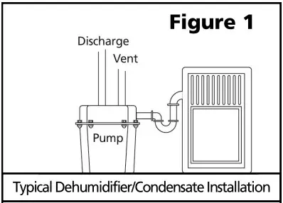
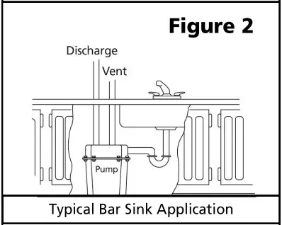
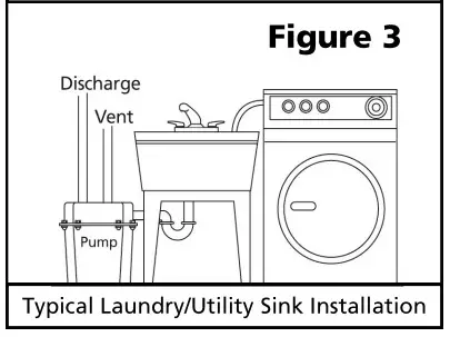
The Superior Pump Sink Pump System is ideal for home wastewater removal from wet bars, laundry tubs, utility and beautician sinks, water softeners and for condensate removal from air conditioners and dehumidifiers. The pump included in this system contain a Permanent Split Capacitor (PSC), oil filled, thermally protected motor. The pump use upper and lower ball bearings which never need lubrication. Pumps come with a vertical type float switch for trouble free pumping. The basin has a 6 gallon capacity and is made from durable polyethylene structural foam. The unique octagonal shape maximizes capacity while minimizing space requirements. The basin is sealed with a molded, reusable PVC gasket and has 1-1/2″ inlet, discharge and vent ports. The pump is pre-assembled in the basin for easy installation.
Specifications
| Model | 92072-U | 92017-U | 92051-U |
| HP | 1/3 | 1/3 | 1/2 |
| Volts | 120 volt AC | 120 volt AC | 120 volt AC |
| Amps | 4.1 Amps | 4.1 Amps | 4.9 Amps |
| Hz | 60 Hz | 60 Hz | 60 Hz |
| Phase | 1 | 1 | 1 |
| Circuit Requirements | 15 Amp (min) | 15 Amp (min) | 15 Amp (min) |
| Pump Discharge Size | 1-1/2″ NPT | 1-1/2″ NPT | 1-1/2″ NPT |
| Max. Solids Handling | 3/8″ Spherical | 3/8″ Spherical | 3/8″ Spherical |
| Max. Liquid Temperature | 120°F | 120°F | 120°F |
| Float Switch Type | Vertical | Vertical | Vertical |
| Cut in (Pump on) Level (Factory Set) | 6″ | 6″ | 6″ |
| Cut-out (Pump off) Level (Factory Set) | 2″ | 2″ | 2″ |
| Cord Length | 10′ | 10′ | 10′ |
| Pump Construction | Thermoplastic | Cast Iron | Cast Iron |
| Impeller | Thermoplastic | Stainless Steel | Stainless Steel |
| Motor Shaft | Stainless Steel | Stainless Steel | Stainless Steel |
| Shaft Seal | Carbon/Ceramid | Carbon/Ceramid | Carbon/Ceramic/ |
| Basin Material | HDPE structural | HDPE structural | HDPE structural |
| Cover Material | HDPE structural | HDPE structural | HDPE structural |
| Cover Gasket | Reusable PVC Seal | Reusable PVC | Reusable PVC Seal |
| Basin Inlet Size | 1-1/2″ | 1-1/2″ | 1-1/2″ |
| Basin Vent & Discharge Size | 1-1/2″ | 1-1/2″ | 1-1/2″ |
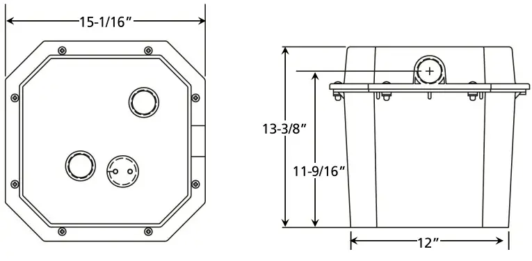
Dimensions
Assembly
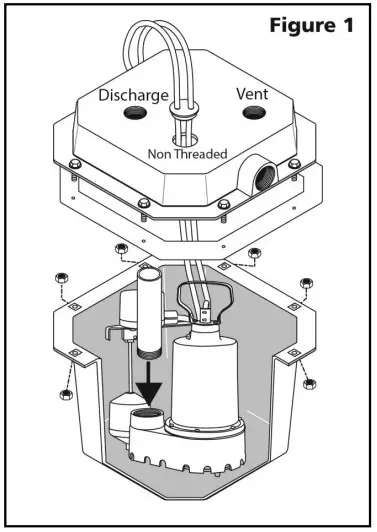
- Install the discharge pipe into the pump discharge as shown in Figure 1. Hand tighten plus one half turn.

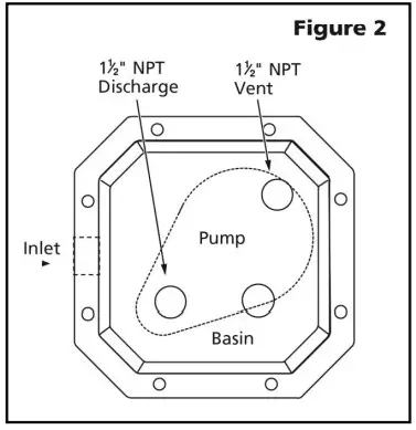
- Place the pump in the basin as shown in Figure 2 and position the discharge pipe so it will line up with the discharge threaded port in the cover.

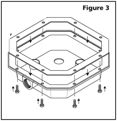
- Turn the basin cover upside down and position the gasket as shown in Figure 3. Push the bolts through the gasket. The gasket will hold the bolts in place to aid in assembly.

- Pull the power cords through the non threaded hole in the cover as shown in Figure 1.
- Position the cover over the discharge pipe.
- Install the cord grommet onto the power cords and then into the non-threaded hole in the basin cover. Do not pull cords tight.
- Fasten the cover to the basin using the bolts that were inserted in Step 2 and eight nuts as shown in Figure 1. Make sure not to over tighten.
Installation
- The basin should be located at the lowest point relative to the area to be drained. See Figures 1, 2 & 3 for typical installations.


- Make sure that the inlet of the pump is lower than the water level to be pumped.
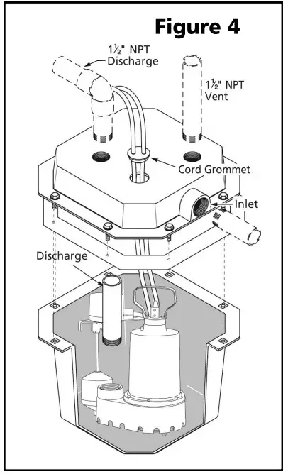
- Install the inlet pipe into the inlet port on the basin as shown in Figure 4. Use Teflon tape or a sealant compatible with plastic to seal any threaded fittings.
 NOTE: If using plastic pipe (PVC or ABS), do not use ordinary pipe joint compound. This compound can degrade plastic pipe and fittings. Use Teflon tape or sealant compatible with plastic pipe.
 - Install the discharge pipe to the discharge port on the basin as shown in Figure 4. Install an in-line check valve in the discharge line as close to the basin as possible. This will prevent backflow into the basin when the pump shuts off.
NOTE: To reduce pumping noise, a check valve with rubber boots can be installed on the discharge pipe to dampen noise and vibration. - Install the vent pipe to the vent port on the basin as shown in Figure 4. The pipe should not extend into the basin. Connect the vent line to the sewer vent system.
- This pump is designed for 120 Volt, 60 Hz. operation and requires a minimum 15 amp individual branch circuit. Both the pump and float switch are supplied with 3 prong, grounding type plugs. The float switch is plugged directly into the outlet. The pump plugs into the piggy-back plug on the float switch plug. See Figure 5.

- If the pump discharge pipe will be exposed to freezing conditions, the exposed portion of the pipe must be installed so any remaining water in the pipe will drain by gravity. Failure to do this can cause water trapped in the pipe to freeze which could result in damage to the pump, piping and personal property.
 NOTE: If using plastic pipe (PVC or ABS), do not use ordinary pipe joint compound. This compound can degrade plastic pipe and fittings. Use Teflon tape or sealant compatible with plastic pipe.
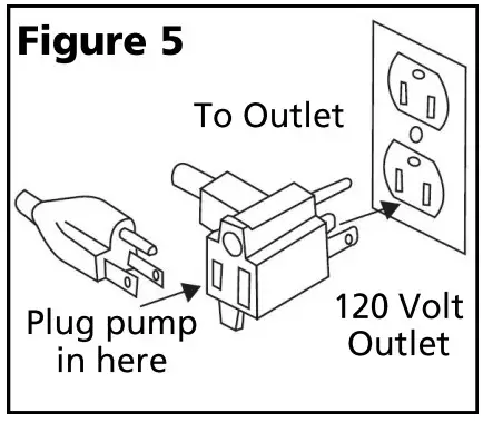
Installation (continued)
Air Admittance Valve (AAV) The use of an Air Admittance Valve (AAV) may be used with this kit if local codes permit. Follow the piping instructions in Figure 6 for proper installation of the AAV.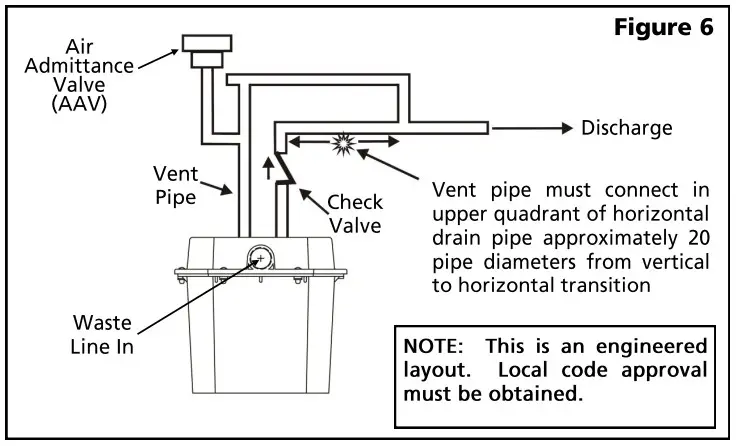
Operation
- After the piping and electrical supply have been installed and connected, the unit is ready for operation.
- Check operation by filling the basin with water and observing the pump through at least one complete cycle.
- Check for leaks and make any necessary adjustments at this time.
Maintenance
![]() DANGER Risk of electric shock. Always disconnect the power supply before attempting to install, service or perform maintenance on the pump.
DANGER Risk of electric shock. Always disconnect the power supply before attempting to install, service or perform maintenance on the pump.![]() WARNING All repairs must be made by an authorized service center.
WARNING All repairs must be made by an authorized service center.![]() CAUTION This submersible pump contains oil which may become pressurized and hot under normal operating conditions – allow the pump to cool for 2-3 hours before servicing.
CAUTION This submersible pump contains oil which may become pressurized and hot under normal operating conditions – allow the pump to cool for 2-3 hours before servicing.
- Periodically inspect and clean the anti-airlock hole.
- Inspect the float switch for any accumulated debris that may inhibit it from operating properly. Clean if necessary.
- The pump has sealed, permanently lubricated bearings and require no additional lubrication.
- In applications where the pump may not activate for extended periods of time, it is recommended to cycle the pump at least once per month to ensure the pumping system is working properly when needed.
Performances
Height and/or piping restriction will reduce the pump output performance. It is recommended to use the same size or larger pipe as the pump discharge for optimum performance.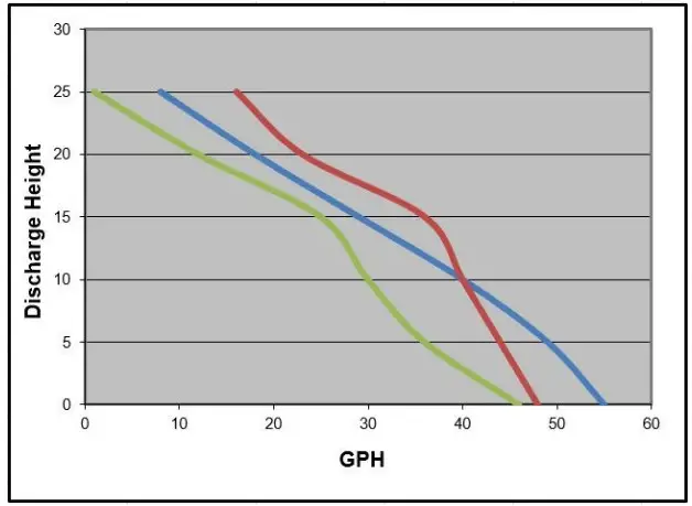
| Model | Discharge Height | 0′ | 5′ | 10′ | 15′ | 20′ | 25′ |
| 92072-U | Gallons Per Minute | 48 | 44 | 40 | 36 | 23 | 16 |
| 92017-U | Gallons Per Minute | 46 | 36 | 30 | 25 | 12 | 1 |
| 92051-U | Gallons Per Minute | 55 | 49 | 40 | 29 | 18 | 8 |
Troubleshooting
| Problem | Possible Causes | How to Correct |
| If the pump does not start or run | Pump is not plugged in, switch or breaker is turned off | Plug pump in or turn on switch/breaker |
| Check for blown fuses or tripped circuit breakers or tripped GFCI outlets | Replace fuse, reset breaker, reset GFCI outlet | |
| Float switch is defective | Check and replace if necessary | |
| Motor thermal protector tripped | Allow pump to cool. Pump will reset automatically | |
| Float switch is stuck or obstructed | Remove obstruction or position pump so it will not become stuck | |
| The pump cycles too frequently or runs periodically when fixtures are not in use. | Backflow of water from discharge pipe | Install or replace check valve |
| Float switch is defective | Replace float switch | |
| Fixtures are leaking | Repair Fixtures to eliminate leakage | |
| If the pump runs but moves little or no water | Obstructed discharge hose/pipe | Remove obstruction |
| Frozen discharge hose/pipe | Allow hose/pipe to thaw | |
| Pump is air locked | Remove | |
| Low line voltage | Check wire size and increase if necessary | |
| Check valve is stuck in the closed position or defective | Inspect, repair or replace if necessary | |
| Check valve is installed backwards | Make sure valve is installed in the correct direction of flow | |
| Worn, damaged or clogged pump parts | Inspect for wear, damage or clog and clean or replace part if necessary | |
| Discharge head exceeds pump capacity | If pumping height is over 25′, the pump will not move water. See performance chart | |
| Pump does not shut off | Float switch is obstructed or stuck | Remove obstruction |
| Defective Float Switch | Replace float switch |
Replacement Parts
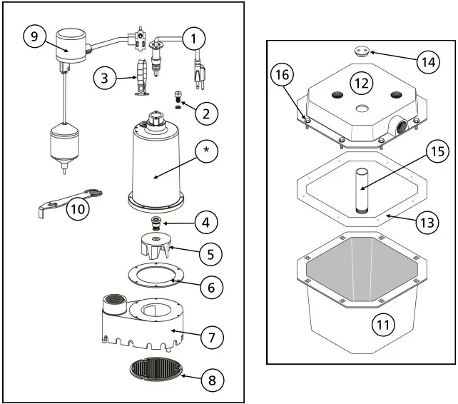
| Ref# | Description | 92072-U | 92017-U | 92051-U |
| 1 | Power Cord | 99108 | 99108 | 99108 |
| 2 | Oil Fill Plug with 0-ring | 99056 | 99056 | 99056 |
| 3 | Handle | 99051 | 99053 | 99053 |
| 4 | Shaft Seal | 99057 | 99057 | 99057 |
| 5 | Impeller | 99065 | 99096 | 99096 |
| 6 | Gasket | 99088 | 99088 | 99088 |
| 7 | BaseNolute | 99098 | 99078 | 99078 |
| 8 | Intake Screen | 99059 | 99073 | 99073 |
| 9 | Float Switch (includes mach, float rod, float ball and grommet) | 92010 | 92010 | 92010 |
| 10 | Vertical float Switch Bracket | 99105 | 99105 | 99105 |
| 11 | 6 Gallon Basin | SFO6B | SFO6B | SFO6B |
| 12 | Basin Cover | SFO6L | SFO6L | SFO6L |
| 13 | Basin Gasket | SEAL06 | SEAL06 | SEAL06 |
| 14 | Cord Grommet | GROMM11-2-10 | GROMM11-2-10 | GROMM11-2-10 |
| 15 | PVC Pipe | 99562 | 99562 | 99562 |
| 16 | Bolts (Qty 8) | HZN5421 | HZN5421 | HZN5421 |
*If motor fails, replace entoire pump
LIMITED WARRANTY – SUMP PUMPS:
Manufacturer warrants the products specified in this warranty to be free from defects in material or workmanship for one (1) year thermoplastic or three (3) year cast iron from date of purchase. During the time period and subject to the terms and conditions, the manufacturer will repair or replace to the original user or consumer any portion of this product which proves to be defective due to materials or workmanship. At all times the manufacturer shall have and possess the sole right and option to determine whether to repair or replace defective equipment, parts, or components. The manufacturer has the option to inspect any product returned under warranty to confirm that the warranty applies before repair or replacement under warranty is approved. This warranty sets forth the manufacturer’s sole obligation and purchaser’s exclusive remedy for defective product. Return defective product to the place of purchase for warranty consideration.
WARRANTY PERIOD – PRODUCTS:
If, within the duration of product use by the original user, this product proves to be defective due to materials or workmanship, the product shall be repaired or replaced at the manufacturer’s option, subject to the terms and conditions set forth in this warranty statement. Proof of purchase is required for warranty consideration. In the absence of suitable proof of the purchase date, the effective period of this warranty is 12 months from the product’s date of manufacture. LABOR, ETC. COSTS: The manufacturer shall IN NO EVENT be responsible or liable for the cost of field labor or other charges incurred by any customer in removing and/or affixing any product, part, or component thereof.
PRODUCT IMPROVEMENTS:
The manufacturer reserves the right to change or improve its products or any portions thereof without being obligated to provide such a change or improvement for units sold and/or shipped prior to such change or improvement.
GENERAL TERMS AND CONDITIONS:
This warranty shall not apply to damage due to acts of God, normal wear and tear, normal maintenance services and the parts used in connection with such service, lightning or conditions beyond the control of the manufacturer, nor shall it apply to products which, in the sole judgment of the manufacturer, have been subject to negligence, abuse, accident, misapplication, tampering, alteration; nor due to improper installation, operation, maintenance or storage; nor to excess of recommended maximums as set forth in the instructions.
Warranty will be VOID if any of the following conditions are found:
- Product is used for purposes other than those for which it was designed and manufactured
- Product not installed in accordance with applicable codes, ordinances, and good trade practices
- Product connected to voltage other than indicated on nameplate or labels
- Pump exposed to but not limited to the following: sand, gravel, cement, grease, plaster, mud, tar, oil, gasoline, solvents or other abrasive or corrosive substances
- Pump has been used for pumping liquids above 120°F
- Pump allowed to operate dry (liquid supply cut off)
DISCLAIMER:
Any oral statements about the product made by the seller, the manufacturer, the representatives, or any other parties do not constitute warranties, shall not be relied upon by the user, and are not part of the contract for sale. Seller’s and the manufacturers only obligation, and buyer’s only remedy, shall be the replacement and/or repair by the manufacturer of the product as described above. NEITHER SELLER NOR THE MANUFACTURER SHALL BE LIABLE FOR ANY INJURY, LOSS OR DAMAGE, DIRECT, INCIDENTAL OR CONSEQUENTIAL (INCLUDING, BUT NOT LIMITED TO, INCIDENTAL OR CONSEQUENTIAL DAMAGES FOR LOST PROFITS, LOST SALES, INJURY TO PERSON OR PROPERTY, OR ANY OTHER INCIDENTAL OR CONSEQUENTIAL LOSS), ARISING OUT OF THE USE OR THE INABILITY TO USE THE PRODUCT, AND THE USER AGREES THAT NO OTHER REMEDY SHALL BE AVAILABLE TO IT. Before using, the user shall determine the suitability of the product for his/her intended use, and user assumes all risk and liability whatsoever in connection therewith.
THE WARRANTY AND REMEDY DESCRIBED IN THIS LIMITED WARRANTY IS AN EXCLUSIVE WARRANTY AND REMEDY AND IS IN LIEU OF ANY OTHER WARRANTY OR REMEDY, EXPRESSED OR IMPLIED, WHICH OTHER WARRANTIES AND REMEDIES ARE HEREBY EXPRESSLY EXCLUDED, INCLUDING BUT NOT LIMITED TO ANY IMPLIED WARRANTY OF MERCHANTABILITY OR FITNESS FOR A PARTICULAR PURPOSE, TO THE EXTENT EITHER APPLIES TO A PRODUCT SHALL BE LIMITED IN DURATION TO THE PERIODS OF THE EXPRESSED WARRANTIES GIVEN ABOVE.
Some states and countries do not allow the exclusion or limitations on how long an implied warranty lasts or the exclusion or limitation of incidental or consequential damages, so the above exclusion or limitations may not apply to you. This warranty gives you specific legal rights, and you may also have other rights which vary from state to state.
![]() Unassembled Sink kit 2020
Unassembled Sink kit 2020


