![]() 35145774 Brushless Submersible Pump
35145774 Brushless Submersible Pump
Instruction Manual
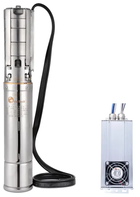
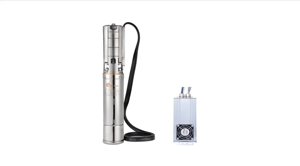
Brushless Submersible Pump
E·Tech DC24V DMX512 Brushless Submersible Pump Manual
Air Cooling DMX512 Driver
E-Tech Technology (Shenzhen) Ltd
Website: www.e-techwater.com
Email: [email protected]
Add.: 1F, Chuangsheng Bldg, Yangguang Industrial Zone, Nanshan, Shenzhen
518055, Guangdong, China.
Tel: 86-755-8364 6618
Fax: 86-755-8364 6516
Air-cooling Driver Working Conditions
- Working Environment: 3~45, 20~90% no condensation.
- Input voltage: DC24-28.8V adjustable voltage power supply.
- Anti-condensation: Switching power supply and driver should be powered on for a long time.
- Dusting regularly.
Pump Working Conditions
- The pump diving depth range should be 0.3~4m, standard water temperature range should be 3~30.
- The water temperature of specially made hot springs should not exceed the range of 3~50.
- It can only be used for pumping clean water with solid content less than 0.01% (by mass):PH value should be 6.5~8.5, chloride ion content should not be more than 400mg/L, hydrogen sulfide content should not be more than 1.5mg/L.
Configuration and Installation
- The rated power of the switching power supply needs to exceed the rate power of water pump by 25%. It is recommended to use isolated PFC power factor correction to prevent harmonic interference.
- The driver should be installed in the distribution box, and it needs at least 8cm distance for exhausting and letting air of the cooling fan.
- The distribution box should be well ventilated, and the inner temperature should not exceed 45 °C. The copper wire of the water pump cable is coated with waterproof glue, it must be completely scraped on the surface of the copper wire with a knife before wiring.
- The contact length of the two butt copper wires shall be more than 20mm and tin plating, shall be performed to ensure insulation and waterproofing.
- It is recommended to connect the water pump cable with solder or clean the copper wire surface of the water pump cable and press the copper connector.
- The switching power supply shall connect to the earth leakage protection, and the equipment will be grounded, and the equipment shell, and tank equipment shell in the pool needs to be equipotential grounding.
Main Power Supply Wiring Mode
Different batches of wire color may be different, subject to actual conditions
| Power Supply-Power Cable | Driver-Power Cable |
| Power Supply+ | Driver 24V+(Red) |
| Power Supply- | Driver 24V-(Black) |
The positive and negative power supply boards cannot be connected inversely, otherwise, the driver will be burned.
Driver and Pump Wiring Mode
Different batches of wire color may be different, subject to actual conditions
| Pump-Phase line | Driver-Phase Cable |
| Pump Brown A | To Driver Brown A |
| Pump Blue B | To Driver Blue B |
| Pump Black C | To Driver Black C |
Water pump reverse and water short can exchange any two-phase wiring sequence, which can be positive.
Start Signal Cable Connection Mode
different batches of wire color may be different, subject to actual conditions
| Speed Adjustment Mode | Signal cable Connection |
| 10K Potentiometers Speed Control | 10K Fixed Resistance connect red (+4.3V) and black (GND), Variable Resistance connect white/green (SD) |
| PLC analog voltage | 1~4V, connected to white/green (SD) and black (GND) |
| Switching start or Start Directly | Connect or short connect to red (+4.3V) and White/Green (SD) |
| DMX512 | Connect red D+, Connect blue D-, Connect black GND |
10K Potentiometers Speed Control-Cable Connection Diagram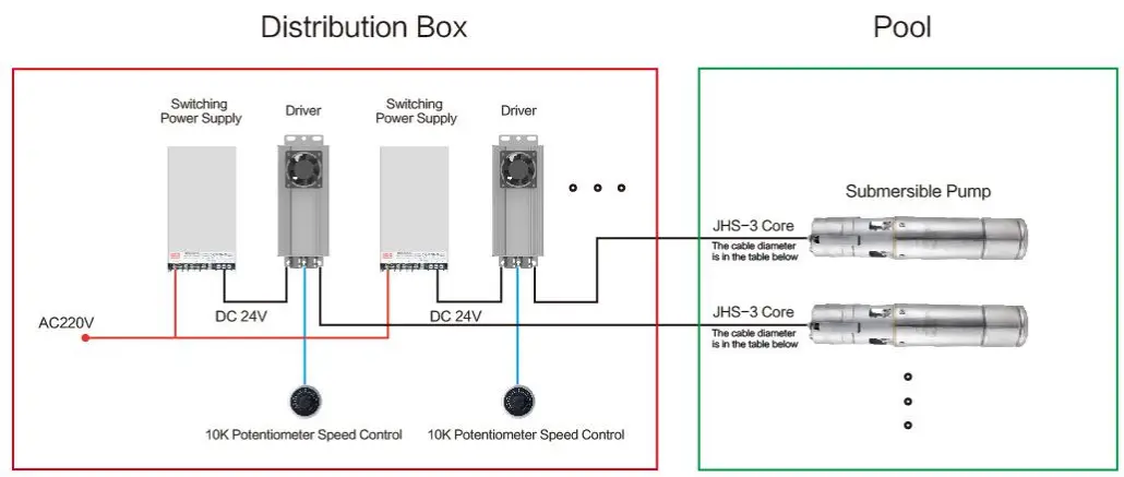 Switching Start or Start Directly-Cable Connection Diagram
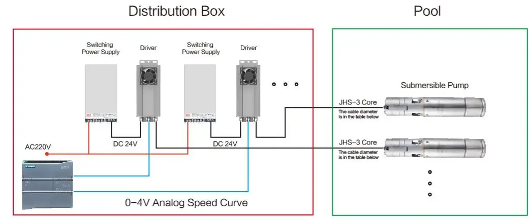 DMX512 Control-Cable Connection Diagram
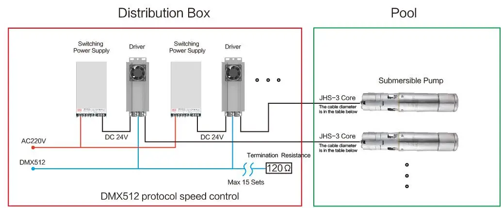
Selection of Air-cooling Driver Cable
The air-cooling driver should be installed in the distribution box, cannot be installed underwater. A 3-core waterproof cable should be used from the driver to the pump underwater. The length of the cable should be less than 25m, and the longest cable should not exceed 50m. Please refer to the following table for wire diameter (Table 1)
| Pump model | MSP200 | 4SP4-5 | 4SP5-8 | 4SP8-94SP5-16 | 4SP8-14 | 4SP8-184SP14-9 | 5SP20-8 | 4SP14-14 |
| Current A | 5.3 | 9 | 12 | 23 | 30 | 33 | 35 | 42 |
| Cable length | Cable Diameter JHS-3 Core*(mm²) | |||||||
| <10m | 1.5 | 1.5 | 2.5 | 4 | 6 | 6 | 6 | 6 |
| <15m | 1.5 | 2.5 | 4 | 6 | 6 | 10 | 10 | 10 |
| <20m | 2.5 | 4 | 4 | 10 | 10 | 10 | 10 | 16 |
| <25m | 2.5 | 4 | 6 | 10 | 16 | 16 | 16 | 16 |
| <30m | 2.5 | 6 | 6 | 10 | 16 | 16 | 16 | 25 |
| <35m | 4 | 6 | 10 | 16 | 16 | 25 | 25 | 25 |
| <40m | 4 | 6 | 10 | 16 | 25 | 25 | 25 | 25 |
| <45m | 6 | 10 | 10 | 16 | 25 | 25 | 25 | 35 |
| <50m | 6 | 10 | 10 | 16 | 25 | 25 | 25 | 35 |
Debugging of Pump and Driver
- Check whether the positive and negative poles of the driver power cable are inversely connected, and test whether the power supply voltage is within DC24-28V.
- Check whether the pump works backward and forwards. The pump’s nameplate indicates the direction of rotation (the water yield will be low when the pump works reversed).
- If some of them have low water yield, check whether the driver and water pump cable are connected inversely (three-phase cable can be arbitrarily changed phase sequence test). If not, adjust the DC24V power supply to a higher level, but not more than DC28.8V. The higher the voltage, the greater the phase cable current, and the greater the water flow. When adjusting the voltage, note that the phase cable current does not exceed the current specified in table 1.
- When the pump speed is adjusted to the maximum power, use a clamp meter to test the phase current between the driver and the pump. Do not exceed the phase current specified in table 1.
- DMX512 speed regulation mode: Each 15 water pump (drivers) shall be equipped with a DMX512 amplifier, and each amplifier shall be connected with a 120terminal resistance.
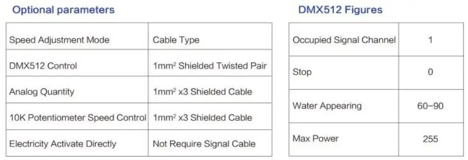
- DMX512 speed control mode: During field debugging, each pump shall test the minimum DMX512 parameter (generally greater than 60~90, which is inversely proportional to the driver input voltage) of outlet water (or pump motor rotation). During programming, the DMX512 start parameter of pump operation must be higher than this parameter, otherwise, when running below this parameter for more than 2 seconds, the driver may start blocking protection (red light flash for 3 times).
Trouble Shooting and Alarm Cause of Indicator Light
| Red Light | Alarm Cause |
| Flash 1 time each second | No start signal |
| The red light is off. | The pump is working properly No power supply Driver overheat protection |
| Quickly Flash 3~7 times | Starting initial (idle) power adjustment is too low, driver and pump phase cable short circuit or poor contact, phase cable is too long or wire diameter is too thin. |
| Slow flash 8 times | Under voltage protection |
| Blue light | The alarming reason (DMX512 speed regulation to have blue light) |
| Flash 1 time each 2 seconds | No start signal |
| Flash 1 time each second | Signal received |
| Continuous flash | Coding successfully |
| Phenomenon | Trouble Cause |
| No water outlet | The drive has no power supply |
| The driver has no speed regulation signal. Check the speed regulation signal type. | |
| The water comes out intermittently and intermittently | The output voltage of the switching power supply is too low. Check the speed regulation signals. |
| DMX512 Software startup preset value is too low (Idle speed value is too low) | |
| Phase cable is too long | |
| Low lever water after using for a period of time. | The water pump inlet or impeller is blocked |
| Pump jitter, water flow is small. | Phase cable is too long or cable diameter is too thin, the current exceeds data on table 1 |
| Check whether any debris is rolled into the water pump filter and impeller. |
E-Tech Technology (Shenzhen) Ltd
Website: www.e-techwater.com
Email: [email protected]
Add.: 1F, Chuangsheng Bldg, Yangguang Industrial Zone
Nanshan, Shenzhen, 518055, Guangdong, China.
Tel: 86-755-8364 6618
Fax: 86-755-8364 6516


