
PCE Instruments PCE-VDL 16I Mini Data Logger
© PCE Instruments
Safety notes
Please read this manual carefully and completely before you use the device for the first time. The device may only be used by qualified personnel and repaired by PCE Instruments personnel. Damage or injuries caused by non-observance of the manual are excluded from our liability and not covered by our warranty.
- The device must only be used as described in this instruction manual. If used otherwise, this can cause dangerous situations for the user and damage to the meter.
- The instrument may only be used if the environmental conditions (temperature, relative humidity, …) are within the ranges stated in the technical specifications. Do not expose the device to extreme temperatures, direct sunlight, extreme humidity or moisture.
- Do not expose the device to shocks or strong vibrations. · The case should only be opened by qualified PCE Instruments personnel. · Never use the instrument when your hands are wet. · You must not make any technical changes to the device. · The appliance should only be cleaned with a damp cloth. Use only pH-neutral cleaner,
no abrasives or solvents. · The device must only be used with accessories from PCE Instruments or equivalent. · Before each use, inspect the case for visible damage. If any damage is visible, do not
use the device. · Do not use the instrument in explosive atmospheres. · The measurement range as stated in the specifications must not be exceeded under
any circumstances. · Non-observance of the safety notes can cause damage to the device and injuries to
the user. - We do not assume liability for printing errors or any other mistakes in this manual.
- We expressly point to our general guarantee terms which can be found in our general terms of business.
- If you have any questions please contact PCE Instruments. The contact details can be found at the end of this manual.
Specifications
Technical specifications
Specification Memory capacity
IP protection class Voltage supply
Interface Operating conditions Storage conditions (ideal for battery) Weight Dimensions
Value
2.5 million readings per measurement 3.2 billion readings with included 32 GB microSD card
IP40 integrated rechargeable Li-Ion battery 3.7 V / 500 mAh Battery charged via USB interface
micro USB
Temperature -20 … +65 °C
Temperature +5 … +45 °C 10 … 95 % relative humidity, non-condensing
approx. 60 g
86.8 x 44.1 x 22.2 mm
© PCE Instruments 29
2.2 Specifications of the different integrated sensors
English
Specification
Temperature °C
Measurement range Accuracy Resolution Max. sampling rate
Relative humidity
Measurement range: Accuracy Resolution Max. sampling rate
Atmospheric pressure
Measurement range Accuracy
Resolution
Light
Measurement range Resolution Max. sampling rate
3 axes acceleration
Measurement range Accuracy Resolution Max. sampling rate
PCE-VDL 16I (5 sensors)
-20 … 65 °C ±0.2 °C 0.01 °C 1 Hz
0 … 100 % RH ±1.8 % RH 0.04 % RH 1 Hz
PCE-VDL 24I (1 sensor)
10 … 2000 mbar ±2 mbar (750 … 1100 mbar); otherwise ±4 mbar 0.02 mbar
0.045 … 188,000 lux 0.045 lux 1 Hz
±16 g ±0.24 g 0.00390625 g 800 Hz
±16 g ±0.24g 0.00390625 g 1600 Hz
2.3 Specification of the battery life
Sampling rate [Hz] 1 Hz 3 Hz 6 Hz 12 Hz 25 Hz 50 Hz 100 Hz 200 Hz 400 Hz 800 Hz 1600 Hz
Battery life PCE-VDL 16I 2d 06h 21min 2d 06h 12min 2d 05h 57min 2d 05h 28min 2d 04h 27min 2d 02h 33min 1d 23h 03min 1d 17h 05min 1d 08h 39min 1d 00h 39min
Battery life PCE-VDL 24I 1d 14h 59min 1d 14h 54min 1d 14h 48min 1d 14h 34min 1d 14h 06min 1d 13h 13min 1d 11h 32min 1d 08h 32min 1d 03h 48min 0d 22h 09min 0d 15h 46min
The specification of the battery life is based on the assumption that the battery is new and fully charged and that the included microSD card, type TS32GUSD300S-A, is used.
© PCE Instruments 30
English
2.4 Specification of the measuring time (2,500,000 readings)
Sampling rate [Hz] 1 Hz 3 Hz 6 Hz 12 Hz 25 Hz 50 Hz 100 Hz 200 Hz 400 Hz 800 Hz 1600 Hz
Measuring time PCE-VDL 16I 5d 18h 53min 4d 03h 12min 2d 05h 58min 1d 19h 24min 0d 23h 56min 0d 12h 51min 0d 06h 40min 0d 03h 24min 0d 01h 43min 0d 00h 51min
Measuring time PCEVDL 24I 28d 22h 26min 9d 15h 28min 4d 19h 44min 2d 09h 52min 1d 03h 46min 0d 13h 53min 0d 06h 56min 0d 03h 28min 0d 01h 44min 0d 00h 52min 0d 00h 26min
The specified measuring times and sampling rates only apply in combination with the microSD card, type TS32GUSD300S-A, which comes with the meter.
2.5 Delivery contents
1x data logger PCE-VDL 16l or PCE-VDL 24I 1x data cable USB A USB Micro 1x 32 GB microSD memory card 1x SD card ejector tool 1x USB pen drive with PC software and user manual
2.6 Optional accessories Part number PCE-VDL MNT
CAL-VDL 16I CAL-VDL 24I
Part description
Adaptor plate with magnetic attachments, screw holes and long holes
Calibration certificate for PCE VDL 16I
Calibration certificate for PCE VDL 24I
© PCE Instruments 31
3 System description
3.1 Introduction Data loggers record parameters important for assessing mechanical and dynamic loads. Transport monitoring, fault diagnosis and load tests are some of the most common areas of application.
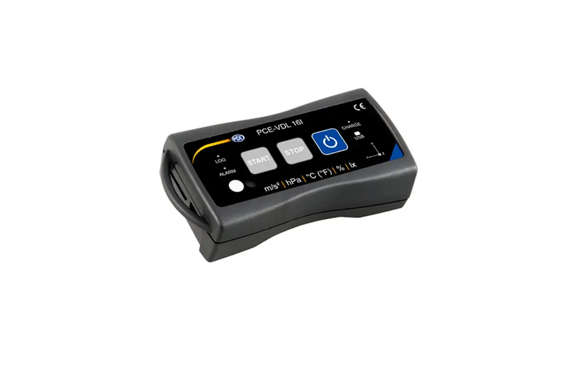
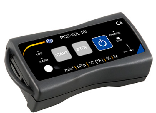
3.2 Device
English
Interfaces 1 Data cable connection: Micro USB 2 SD card slot
Key functions 7 On / off 8 STOP: stop the measurement 9 START: start the measurement
LED indicators
Sensor positions: PCE-VDL 16I only
3 LOG: status indicator / log interval
10 Humidity sensor
4 ALARM: red when limit value is exceeded 11 Light sensor
5 CHARGE: green when charging
6 USB: green when connected to PC
© PCE Instruments 32
English
3.3 MicroSD card in the data logger Insert the microSD card into the SD card slot with two fingers and use the SD card ejector tool to push it until it snaps into place.
To remove the microSD card from the data logger, insert the ejector tool into the SD card slot. The memory card is then released from ist retainer and snaps out of the case so that it can be taken out. To read out the data, insert the microSD card into a PC, together with its adaptor.
© PCE Instruments 33
English
4 Getting started
4.1 Attachment of the optional adaptor plate PCE-VDL MNT You can attach the data logger to an adaptor plate. The data logger can then be attached to the measurement object by means of the boreholes or the parallel long holes. The rear side of the adaptor plate is magnetic so that it is no problem to attach it to magnetic substrates. The adaptor plate is particularly useful when oscillation, vibration and shocks are recorded as the data logger should be firmly attached to the measurement object to ensure accurate readings.
4.2 Attachment without using the adaptor plate If you do not wish to use the optional adaptor plate PCE-VDL MNT, the data logger can be attached in any position at the measurement object. If parameters like temperature, humidity or air pressure and light are measured, it is normally sufficient to place or clamp the data logger onto the measuring point. The data logger can also be suspended by its guard bracket. 4.3 SD card If you use an SD card that is not part of the delivery contents, you have to format the SD card before use (FAT32 file system). For high sampling rates of the acceleration sensor (800 Hz for PCE-VDL 16I and 1600 Hz for PCE-VDL 24I), you will need at least a Class 10 (U1) microSD card. The specification of the battery life only applies if the included microSD card is used.
© PCE Instruments 34
Operation
5.1 Connecting the data logger to your PC To be able to make the different sensor settings in the software, connect the data cable to the PC and to the Micro USB connection of the data logger. The Charge and USB LEDs glow. When the battery is charged, the CHARGE LED will stop glowing automatically.
English
Press
to turn on/off the data logger.
5.2 System requirements for PC software
· Operating system Windows 7 or higher · USB port (2.0 or higher) · An installed .NET framework 4.0 · A minimum resolution of 800×600 pixels · Optional: a printer · Processor with 1 GHz · 4 GB RAM · A data logger (“PCE-VDL 16I” or “PCE-VDL 24I”)
Recommended: Operating system (64 Bit) Windows 7 or higher At least 8 GB main memory (the more, the better)
5.3 Software installation Please run the ” Setup PCE-VDL X.exe ” and follow the instructions of the setup.
© PCE Instruments 35
English
5.4 Description of the user interface in the software
The main window consists of several areas: Below the title bar there is a “toolbar”, the icons of which are functionally grouped. Below this toolbar, there is a list of measurement series, in the left part of the window. The right-hand part of the window shows an overview of a selected series of measurements. At the bottom of the main window there are two “status bars” containing important information, directly above each other. The lower of the two shows the static settings of the program which can be set via a settings dialog. The upper status bar shows the dynamic settings of the “PCE-VDL X” which are retrieved directly from the connected device. This also applies to the information if a measurement is currently made or what data logger model is connected (“PCE-VDL 16I” or “PCE-VDL 24I”). 5.5 Meaning of the individual icons in the toolbar of the PC software
Group “Connection” Connect to the “PCE-VDL X”
Disconnect from the “PCE-VDL X”
Group “Data Logger” Start a measurement
Stop a measurement
Test sensors
© PCE Instruments 36
English
Information on a connected data logger Group ,,Series of Measurements”
Load a series of measurements from cache Remove series of measurements from program memory Delete series of measurements permanently
Group ,,Sensors” Temperature sensor Humidity sensor Light sensor Pressure sensor Acceleration sensor
Group ,,Views” Tabular view Graphical view Graphical and tabular view Statistics
© PCE Instruments 37
English
Group “Settings” Open settings dialog for static device data Open settings dialog for dynamic device data Select one of the languages supported by the program
Group “Program” Display an information dialog Exit the program
6 Operation
6.1 The first use of the software Before the “PCE-VDL X” can work with the software, the assigned COM port must be set in the software once. It can be set via the “Settings” dialog .
In addition to the connection data, further settings for the different views of series of measurements as well as for the date and time format can be made here.
© PCE Instruments 38
“Only show windows of current series of measurements” hides views that do not belong to the
currently selected series of measurements. When this mode is active, the lower status bar of the main window will show the text “Single”.
English
If you select “Show all windows of each series of measurements” instead, all views of all loaded series of measurements will be shown. In this case, the lower status bar of the main window will show the text “Multiple”.
Via the button “Change…”, the standard size of the windows for all views can be set.
6.2 Connect to the “PCE-VDL X”
After the desired settings have been made, close the Settings window by clicking on the “Apply” button.
Turn on the data logger before you proceed.
Press the
key.
The LOG LED starts flashing approx. every 10 seconds.
Now click on the icon in the toolbar of the main window, in the group ,,Connection”. If the connection could be successfully established, the status bar for dynamic data will show, for example, the following in green:
If the button changes to , this means that the connection is active. 6.3 Disconnect from the ” PCE-VDL X” By clicking on the icon, an active connection to the “PCE-VDL X” can be terminated. The icon indicates that the connection has been interrupted.
By clicking on the icon, an active connection to the “PCE-VDL X” can be terminated.
6.4 Switch off the data logger When the data logger is on, the LOG LED flashes.
Press the
key when the meter is on to stop the LOG LED from flashing and to switch off the
data logger. In the display field of the status bar, you will see the following in green:
If the data logger is turned off manually, a new configuration via the Logger” is required, see chapter “Start a measurement”.
button in the group “Data
© PCE Instruments 39
6.5 Retrieve information on connected data logger
If the connection to the “PCE-VDL X” was successfully established, some important information on the data logger can be retrieved and displayed.
This is done by clicking on the icon
in the group “Data Logger”.
English
Along with the firmware and file versions, the following information will be displayed here: – the volume name, the status and the capacity of the SD card – the status if there is an active measurement – the current battery voltage – date and time (optional) – serial and part number of the VDL X
© PCE Instruments 40
6.6 Test the sensors When a connection to the “PCE-VDL X” is active, a window with the current values of all available
sensors can be displayed by clicking on the
icon in the group “Data Logger”.
Note: The values displayed in that window are continuously queried. This means that the data
are live data.
English
© PCE Instruments 41
6.7 2-point calibration of the temperature and humidity sensors The software allows calibration of the temperature sensor and of the humidity sensor.
By clicking on the icon two sensors.
in the group ,,Settings”, you can open a dialog for calibration of these
English
Calibration dialog
The procedure is as follows:
– Select sensor (temperature or humidity)
– Enter set point 1 and actual value 1 manually. – Enter set point 2 and actual value 2 manually.
– Select second sensor (temperature or humidity)
– Enter set point 1 and actual value 1 manually. – Enter set point 2 and actual value 2 manually.
– Confirm by clicking on “Apply”.
When you click on the respective ,,Current” button, the current sensor value will be entered in the field for the respective actual value.
As the calibration data can be saved and loaded, it is always possible to interrupt the procedure by saving the current data and loading them again later. Closing the calibration dialog by clicking on the ,,Apply” button and sending the calibration data to the data logger is only possible if both set points and actual values of both sensors have been assigned valid values.
For the set points and actual values, a certain range of values is available. More information can be found in the chart “Calibration data”:
Sensor
Temperature Humidity
Minimum difference between reference points
20 °C 20 % RH
Maximum difference between set point and actual value
1° C
5 % RH
© PCE Instruments 42
English
6.8 Start a measurement To prepare a new measurement for the “VDL X”, click on the icon in the group “Data Logger”. In the window that is now displayed, not only the involved sensors can be set but also the start and stop conditions.
In the ,,Sensors” area, the available sensors of the data logger can be included in a measurement by ticking the box in front of the sensor name. At the same time, you can set if the LOG LED should flash during the measurement. You can also set a sampling rate for each sensor. For the temperature, humidity, pressure and light sensors, you can set a sampling rate between 1 and 1800 s (30 minutes). The smaller the value entered, the more measurements are made. For the acceleration sensor, you can select a value between 1 and 800 / 1600 (depending on your requirements). The higher the value entered, the more measurements are made. You can also set alarm values for the temperature, humidity, pressure and light sensors.
© PCE Instruments 43
English
You can set a minimum value as the lower limit and maximum value as the upper limit. If the measured value of at least one of these sensors is outside this set range, the data logger’s LED will flash in red. The red LED will go off as soon as all readings are back within the set range.
A measurement can be started in three different ways: – Instant: When the window for starting a measurement is closed by clicking on ,,Apply”, the measurement is started.
– By keystroke: The measurement is started when the Start or Stop key of the data logger is pressed.
– By time: You can set a date and time or a duration for starting a measurement.
Note 1: By clicking on the ,,By time” button, you can take over the current time of your PC as the time shown in that window.
Note 2: The data logger synchronizes its internal clock with the PC time every time a new measurement is prepared.
A measurement can be stopped in two different ways: – By keystroke: The measurement is stopped when the Start or Stop key of the data logger is pressed.
– By time: You can set a date and time or a duration for starting a measurement.
Note: By clicking on the ,,By time” button, you can take over the current time of your PC as the time shown in that window.
Of course, an ongoing measurement can always be terminated manually via the software, by clicking on the icon in the group “Data Logger”. Selecting the duration of a measurement
If “By time” is selected for both start and stop, either a start and stop time or a start time and duration can be specified.
The stop time is changed automatically as soon as either the start time or the duration is changed. The resulting stop time is always calculated from the start time plus the duration.
© PCE Instruments 44
English
6.9 Transfer and load series of measurements
The readings of an ongoing measurement are saved to a microSD card in the data logger. Important: A file can contain a maximum of 2,500,000 readings to be processed directly by the software. This number is equivalent to a file size of approx. 20 MB. Files that contain more readings per sensor cannot be loaded directly. There are two ways to transfer these files from the data logger to the PC:
– A click on the icon in the group “Series of Measurements” opens a new window where the available files with measurement data are listed. As the files with measurement data can easily become quite large, depending on the set sampling rate, these are saved to a buffer on the PC after they have been transferred from the data logger
to the PC once so that they can be accessed much more quickly after this.
Note:
The data logger works with a baud rate of max. 115200 baud.
The resulting data rate is fast enough for communication but rather unsuitable to transfer huge amounts of data as the file size is quite big.
Therefore, the window where the series of measurements are listed is bicoloured: The entries written in black (“local file”) are measurement series that are already saved in the fast
cache of the PC.
The entries in red, bold letters, which appear with an estimated loading time, are only saved on the SD card of the data logger so far.
There is also a much quicker way to transfer series of measurements to the software. You only need to remove the SD card from the data logger and insert it into a suitable USB adaptor
(external USB drive).
This drive is visible in the Windows Explorer and its files can be imported into the software by drag and drop, either individually or in groups.
After doing this, all series of measurements are available from the fast cache of the PC.
1)
Remove the SD card from the datalogger and connect it via adapter as an
external drive to the PC.
2)
Open MS Windows Explorer and then open the external drive with the SD
card.
3)
Now open the folder by double-clicking on it.
4)
Click on one of the files and hold the left mouse button.
5)
“Drag” the file into the main window of the PCE-VDL software, then “drop” it
to load the file.
© PCE Instruments 45
English
Notes: The name of the file must be in the format “YYYY-MM-DD_hh-mm-ss_log.bin” no other file formats can be imported. After the import, the file can be loaded as usual via the “Load series of measurements” button in the toolbar. The import is not made synchronously via the main program of the PCE-VDL software. Therefore, there will be no feedback when the import is finished. When you open a series of measurements, you can assign an individual name to it.
List of measurement series
© PCE Instruments 46
6.10 Delete series of measurements
A series of measurements saved to the software memory can be removed from the memory in two different ways: – Select a series of measurements from the list and press the ,,Del” key on your keyboard or
– Select a series of measurements from the list and click on the icon Measurements”.
in the group “Series of
A series of measurements deleted this way can be re-loaded from the quick memory at any time.
However, if you want to delete a series of measurements irrevocably, you must click on the icon in the group “Series of Measurements”.
A window with an overview of all measurement series from the PC’s quick access or which are only saved on the SD card of a connected data logger is shown first (similar to loading series of measurements).
Now you can select one or more series of measurements you wish to delete.
A confirmation prompt will then appear, asking you to confirm if you really wish to delete these series of measurements.
Depending on the location of the measurement series to be deleted, they are either deleted from the PC’s quick access only or from the SD card of the data logger.
English
Note: Please bear in mind that this type of deletion is permanent!
© PCE Instruments 47
6.11 Evaluate series of measurements
The software of the data logger offers various types of views to visualize the sensor data of the series of measurements.
When at least one series of measurements has been loaded and selected, you can click on one
of these icons:
. to select one or several sensors.
After selecting the sensors, you can select the view. The corresponding icons can be found in the
group ,,Views”. As soon as at least one sensor has been selected, you can open a certain view in a new window
by
clicking
on
one
of
these
sensors:
.
All windows that belong to a series of measurements are listed in the left-hand part of the main window, below the corresponding series of measurements.
English
Example: four views that belong to one series of measurements
In the “settings dialog” which can be opened with the icon have two options regarding the view:
from the group “Settings”, you
– “Only show windows of the current series of measurements” (“Single” in the status bar)
or – “Show all windows of all series of measurements” (“Multiple” in the status bar)
If you choose to only show the windows of the current series of measurements, all views will be hidden when a different series of measurements is selected, except for that of the current series of measurements,. This (standard) setting makes sense if you wish to have several series of measurements opened in the software but only want to view one of them.
The other option is to show all views of all opened series of measurements. This setting makes sense if you only have very few series of measurements opened at the same time and want to compare them.
© PCE Instruments 48
6.11.1 Tabular view
English
The tabular view gives a numerical overview of a series of measurements. The sensors you have selected previously will be shown in columns next to each other.
The first four columns show the chronological sequence. The chart can be sorted by any of its columns, by clicking on the column heading.
If one or more lines are highlighted, you can copy their content into the clipboard with the shortcut “CTRL + C” and remove it from the clipboard and insert it with the shortcut “CTRL + V”.
Data export
Via the button
“Data Export”, either a previously made selection of lines or the complete
content of the chart can be exported in CSV format.
Selection: Only selected or all records?
© PCE Instruments 49
6.11.2 Statistics
English
This view shows statistical data about a series of measurements. The previously selected sensors are shown in columns next to each other again.
The following information can be shown here: Quantity of measuring points, minimum and maximum, average, standard deviation, variance, span, standard error and (optionally) the median. If one or more lines are highlighted, you can copy their content into the clipboard with the shortcut “CTRL + C” and remove it with the shortcut “CTRL + V”.
Data export
Via the button
“Data Export”, either a previously made selection of lines or the complete
content of the chart can be exported in CSV format.
Selection: Only selected or all records?
© PCE Instruments 50
English
6.11.3 Graphical view
This view shows the values of the previously selected sensors in a graphic. The reading of the sensor with its specific unit can be found on the y axis and the chronological sequence (duration) can be found on the x axis. Zoom a graphic area or move the zoomed graphic A freely selectable part of the displayed graphic can be enlarged. To be able to do so, the respective icon in the toolbar (“Enlarge the graphic area (“Zooming”) or move the enlarged graphics) must be a magnifying glass. Then, a rectangle can be drawn over a part of the graphics by holding the mouse button down. When the mouse is released, the selected area appears as a new graphic.
“Zooming” the graphic © PCE Instruments
51
English
As soon as at least one enlargement has been made, it is possible to switch from enlargement mode to shift mode by clicking the icon (“Enlarge the graphics area (“Zooming”) or move the enlarged graphics) with the magnifying glass icon. This mode is represented by the hand icon. If the mouse is now placed over the graphics area and then the left mouse button is pressed, the depicted section can be moved by holding the mouse button down. Another click on the hand icon changes back to the enlargement mode, which is recognizable by the magnifying glass icon.
Shifting the “zoomed” graphic Restore original graphic
Restored (original) graphic The original graphic can be restored at any time by clicking on the corresponding icon (“Restore original graphic”) next to the magnifying glass or hand.
© PCE Instruments 52
English
Change background and representation of graphic The background of the graphics and its representation can be changed via the icon (“Change background and representation of graphic”) to the right. A click on the icon works like a switch: A single click makes the division of the background finer and adds some more dots to the graphics. A further click on the icon changes back to standard view.
Finer resolution and shown dots As long as the individual dots are shown, placing the mouse cursor on a dot within the displayed line will open a small information window with the data (time and unit) of the currently selected reading.
Information on a selected dot © PCE Instruments 53
English
Print currently viewed graphic The currently displayed graphics can be printed. You can open the “Print” dialog by clicking on the corresponding icon (“Print currently viewed graphic”). Save currently viewed graphic The currently displayed graphics can be saved. You can select the location for saving the graphics by clicking on the corresponding icon (“Save currently viewed graphic”). 6.11.4 Mixed view (graphical plus tabular)
This view consists of the graphical view together with the tabular view. The correlation between the two views is the advantage of the mixed view. When you double-click on one of the dots in the graphical view, the same entry will automatically be selected in the tabular view.
© PCE Instruments 54
English
7 Possible error messages
Source SD card SD card SD card SD card SD card
Code 65 66 67 68 69
Text Read or write error File cannot be opened Folder on the SD card is unreadable A file could not be deleted No SD card found
Example: “No SD card found”
© PCE Instruments 55
English
8 Warranty
You can read our warranty terms in our General Business Terms which you can find here: https://www.pce-instruments.com/english/terms.
9 Disposal
For the disposal of batteries in the EU, the 2006/66/EC directive of the European Parliament applies. Due to the contained pollutants, batteries must not be disposed of as household waste. They must be given to collection points designed for that purpose. In order to comply with the EU directive 2012/19/EU we take our devices back. We either re-use them or give them to a recycling company which disposes of the devices in line with law. For countries outside the EU, batteries and devices should be disposed of in accordance with your local waste regulations. If you have any questions, please contact PCE Instruments.
© PCE Instruments 56
English
© PCE Instruments 57
English
PCE Instruments contact information
Germany
PCE Deutschland GmbH Im Langel 4 D-59872 Meschede Deutschland Tel.: +49 (0) 2903 976 99 0 Fax: +49 (0) 2903 976 99 29 [email protected] www.pce-instruments.com/deutsch
United Kingdom
PCE Instruments UK Ltd Unit 11 Southpoint Business Park Ensign Way, Southampton Hampshire United Kingdom, SO31 4RF Tel: +44 (0) 2380 98703 0 Fax: +44 (0) 2380 98703 9 [email protected] www.pce-instruments.com/english
The Netherlands
PCE Brookhuis B.V. Institutenweg 15 7521 PH Enschede Nederland Telefoon: +31 (0)53 737 01 92 [email protected] www.pce-instruments.com/dutch
United States of America
PCE Americas Inc. 711 Commerce Way suite 8 Jupiter / Palm Beach 33458 FL USA Tel: +1 (561) 320-9162 Fax: +1 (561) 320-9176 [email protected] www.pce-instruments.com/us
France
PCE Instruments France EURL 23, rue de Strasbourg 67250 Soultz-Sous-Forets France Téléphone: +33 (0) 972 3537 17 Numéro de fax: +33 (0) 972 3537 18 [email protected] www.pce-instruments.com/french
Italy
PCE Italia s.r.l. Via Pesciatina 878 / B-Interno 6 55010 Loc. Gragnano Capannori (Lucca) Italia Telefono: +39 0583 975 114 Fax: +39 0583 974 824 [email protected] www.pce-instruments.com/italiano
China
PCE (Beijing) Technology Co., Limited 1519 Room, 6 Building Zhong Ang Times Plaza No. 9 Mentougou Road, Tou Gou District 102300 Beijing, China Tel: +86 (10) 8893 9660 [email protected] www.pce-instruments.cn
Spain
PCE Ibérica S.L. Calle Mayor, 53 02500 Tobarra (Albacete) España Tel. : +34 967 543 548 Fax: +34 967 543 542 [email protected] www.pce-instruments.com/espanol
Turkey
PCE Teknik Cihazlari Ltd.ti. Halkali Merkez Mah. Pehlivan Sok. No.6/C 34303 Küçükçekmece – stanbul Türkiye Tel: 0212 471 11 47 Faks: 0212 705 53 93 [email protected] www.pce-instruments.com/turkish
Hong Kong
PCE Instruments HK Ltd. Unit J, 21/F., COS Centre 56 Tsun Yip Street Kwun Tong Kowloon, Hong Kong Tel: +852-301-84912 [email protected] www.pce-instruments.cn
© PCE Instruments 58
User manuals in various languages (français, italiano, español, português, nederlands, türk, polski, , ) can be found by
using our product search on: www.pce-instruments.com Specifications are subject to change without notice.
© PCE Instruments
References
 France.fr : Actualités, destinations et infos du tourisme en France
-
iberica.es
 Make an offer on the domain instruments.co.uk - Domains.co.uk
-
Computer Instruments | Home
 Discover Italy: Official Tourism Website - Italia.it
-
PCE(北京)科技有é™å…¬å¸
-
Industrial Measurement Products and Solutions | PCE Instruments
-
PCE Deutschland GmbH Prüfgeräte vom Hersteller | PCE Instruments
-
PCE Brookhuis B.V. | PCE Instruments
-
PCE Americas Inc. : Test Instruments | PCE Instruments
-
PCE Iberica S.L. Instrumentación | PCE Instruments
-
PCE Instruments France | PCE Instruments
-
PCE Italia s.r.l. / Strumenti di Misura | PCE Instruments
-
PCE Teknik Cihazlar Paz. Tic. Ltd.Şti. | PCE Instruments
-
PCE Americas Inc. : Test Instruments | PCE Instruments
-
PCE Deutschland GmbH Prüfgeräte vom Hersteller | PCE Instruments
-
PCE Americas Inc. : Test Instruments | PCE Instruments


