Honeywell SOMAT39 Luzon Wi-Fi and BT Module

Introduction
This document specifies the details for a WiFi 802.11a/b/g/n/ac with BT4.1 RFSOM module called with Honeywell Part No. uzon Module will use WM-BAC-AT-39 USI SiP module with Qualcomm QCA6174A chip set which includes LNA, switch, and internal power amplifier VSWR. The module will perform with all legacy hardware having data rates as low as 1Mbps. This chipset also supports concurrent operation of Bluetooth (Version 4.1) for wireless connectivity during browsing or other device applications. Along with both standard and high speed (HS) Bluetooth data rates, Bluetooth low energy modes are also supported. Hardware WAPI acceleration engine, AES, TKIP, WPA and WPA2 are supported to provide the latest security requirement on your network. For placing the SOMAT39 onto the carrier board, the part number to be used is SOMAT39 is meant to be used inside Honeywell only. It
is not meant or designed to be sold independently outside Honeywell
SOMAT39 – System on Module Features
- IEEE 802.11 a/b/g/n/ac WLAN
- Bluetooth 4.2 + HS
- Bluetooth-WLAN coexistence
- WiFi Wake on Wireless (WoW)
- 20/40 MHz bandwidth at 2.4GHz
- 20/40/80 MHz bandwidth at 5GHz
- Internal PA/LNA
- RF SOM Size: 15 mm x 15 mm, LGA Package
- 802.11 k/v/r [will be available in next release]
- Low Current consumption in IEEE PS and Deep Sleep
- WiFi Security methods: OPEN, WEP, WPA2-PSK, WPA2-1X (PEAP-MSCHAPV2, PEAP-TLS, EAP-TTLS)
- WiFi + BT Coexistence with simultaneous video streaming over WiFi and voice call over BT.
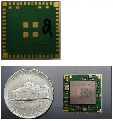
- Weight of module ~ 1gram
- Featuring integrated IEEE 802.11 a/b/g/n/ac + BT4.1.
- 60 pins LGA.
- Future to support two streaming dual-band antennas.
- Low power consumption & excellent power management performance extends battery life.
Block Diagram
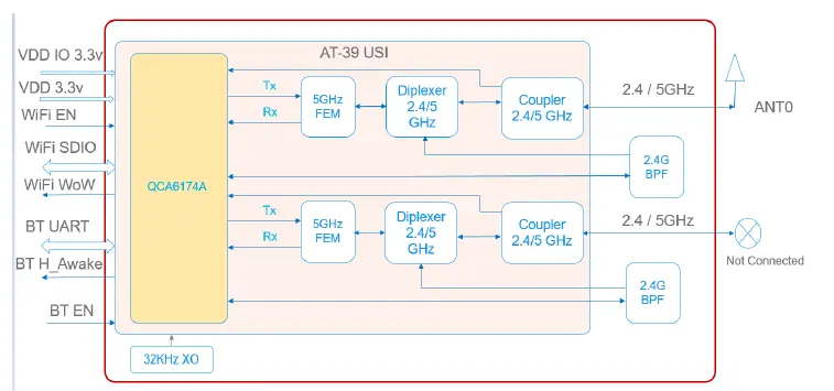
SOMAT39 module is designed based on Qualcomm QCA6174A chipset solution. It supports a generic SDIO, UART interface to connect the WLAN/BT to the host processor. A simplified block diagram of the WM-BAC-AT-39 module is depicted in above picture.
Technical Specifications
Absolute Maximum Rating
| Power Supply: | Max +3.6v |
| Storage Temperature: | – 40° to 125° Celsius |
| Voltage ripple: | ± 2% (Max. Values not exceeding Operating voltage) |
| Maximum RF input (reference to 50 Ω input): | 0dBm |
| Digital I/O input voltage for 3.3 V I/O supply: | Vdd + 0.3 V |
| Digital I/O input voltage for 1.8 V I/O supply: | Vdd + 0.2 V |
Recommended Operating Condition
| Operating Temperature: | -20° to 65°C |
| Humidity | Max 85% (Non-condensing, relative humidity) |
| Voltage | VDD3P3: 3.3v +/- 0.1V VDDIO: 3.3v +/- 0.1vV (*1.8V for higher > 50MHz SDIO clock versions) |
| Current Consumption | Tx output power @ 19 dBm on 11b 1M (single stream): 420mA (typ), 490mA (max)
**Tx output power @ 16 dBm on 11n MCS8_HT20 (dual stream): 620mA (typ), 720mA (max)
Tx output power @ 15 dBm on 11n MCS0_HT20 (single stream-5g): 470mA (typ), 540mA (max)
**Tx output power @ 13 dBm on 11n MCS0_VHT80 (dual stream-5g): 715mA (typ),820mA (max) |
| ** Dual Streaming Current Consumption Data is for reference purpose only. Existing capability for SOMAT39 is enabled for single streaming only.
NOTE: Peak current bursts of 1.1A is observed during tests. Power supply input to RFSOM must support peak current of 1.1A. | |
NOTE:
Peak current bursts of 1.1A is observed during tests. Power supply input to RFSOM must support a peak current of 1.1A.
Foot Print, Front & Back view
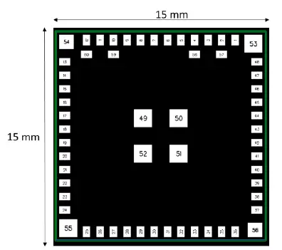
Note: Bottom View of RF SOM Module – LGA Package Footprint
Pin Configurations
| S.No | PINOUT | Signal Type | Signal Description |
| 1 | IO1 | Input/Output | BT_DEV_WAKE |
| 2 | GND | Ground | Ground |
| 3 | RF_ANT1 (WiFi) | RF Output | RF Antenna 1 WiFi Output |
| 4 | GND | Ground | Ground |
| 5 | IO2 | Input/Output | BT_HOST_WAKE |
| 6 | IO3 | Input/Output | GPS_COEX_WOW |
| 7 | IO4 | Input/Output | BT_PCM_OUT |
| 8 | IO5 | Input/Output | BT_EN |
| 9 | IO6 | Input/Output | WL_EN |
| 10 | GND | Ground | Ground |
| 11 | RF_ANT0 (WiFi/BT) | RF Output | RF Antenna 0 WiFi/BT Output |
| 12 | GND | Ground | Ground |
| 13 | IO7 | Input/Output | LTE_SYNC_TMS |
| 14 | IO8 | Input/Output | BT_PCM_IN |
| 15 | IO9 | Input/Output | BT_PCM_CLK |
| 16 | IO10 | Input/Output | BT_PCM_SYNC |
| 17 | IO11 | Input/Output | PCIE_WAKE_L |
| 18 | IO12 | Input/Output | PCIE_CLKREQ_L |
| 19 | IO13 | Input/Output | PCIE_RST_L |
| 20 | IO14 | Input/Output | LTE_PRI_TCK |
| 21 | IO15 | Input/Output | USB_DN |
| 22 | IO16 | Input/Output | USB_DP |
| 23 | VDD1 | Power Supply | Power Supply for IO’s |
| 24 | GND | Ground | Ground |
| 25 | PCIE_REFCLK_P | Clock Diff. Input +ve | PCIE Clock Diff. input Positive |
| 26 | PCIE_REFCLK_N | Clock Diff. Input -ve | PCIE Clock Diff. input Negative |
| 27 | GND | Ground | Ground |
| 28 | PCIE_TX_P | Transmit Diff. Output +ve | PCIE Transmit Diff. Output Positive |
| 29 | PCIE_TX_N | Transmit Diff. Output -ve | PCIE Transmit Diff. Output Negative |
| 30 | GND | Ground | Ground |
| 31 | PCIE_RX_N | Receive Diff. Input -ve | PCIE Receive Diff. Output Negative |
| 32 | PCIE_RX_P | Receive Diff. Input +ve | PCIE Receive Diff. Output Positive |
| 33 | GND | Ground | Ground |
| 34 | IO17 | Input/Output | LTE_ACTIVE_TDI |
| 35 | IO18 | Input/Output | SDIO_INT_TDO |
| S.No | RF SOM SOM PINOUT | Signal Type | Signal Description |
| 36 | VDD2 | Power Supply | Power Supply – SOM VDD3V3 |
| 37 | VDD3 | Power Supply | Power Supply – SOM VDD3V3 |
| 38 | SDIO_DATA_0 | Data Bidirectional output 0 | Serial Data IO Data 0 |
| 39 | SDIO_DATA_1 | Data Bidirectional output 1 | Serial Data IO Data 1 |
| 40 | SDIO_DATA_2 | Data Bidirectional output 2 | Serial Data IO Data 2 |
| 41 | SDIO_DATA_3 | Data Bidirectional output 3 | Serial Data IO Data 3 |
| 42 | SDIO_CMD | SDIO Command input | SDIO Command input |
| 43 | SDIO_CLK | SDIO Clock input | SDIO Clock input |
| 44 | GND | Ground | Ground |
| 45 | IO19 | Input/Output | BT_UART_TXD |
| 46 | IO20 | Input/Output | BT_UART_RXD |
| 47 | IO21 | Input/Output | BT_UART_CTS |
| 48 | IO22 | Input/Output | BT_UART_RTS |
| 49 | GND | Ground | Ground |
| 50 | GND | Ground | Ground |
| 51 | GND | Ground | Ground |
| 52 | GND | Ground | Ground |
| 53 | GND | Ground | Ground |
| 54 | GND | Ground | Ground |
| 55 | GND | Ground | Ground |
| 56 | GND | Ground | Ground |
| 57 | GND | Ground | Ground |
| 58 | GND | Ground | Ground |
| 59 | GND | Ground | Ground |
| 60 | GND | Ground | Ground |
Wireless Specifications
WLAN
The SOMAT39 module complies with the following features and standards;
| Features | Description |
| WLAN Standards | IEEE 802 11a/b/g/n/ac |
| Antenna Port | Support 1 streaming with Ant 0 (Ant1 is disabled) |
| Frequency Band | 2.400 GHz – 2.484 GHz 4.900 GHz – 5.845 GHz |
| Number of Sub Channels | 1~ 11Channels 36~ 48,52~ 64, 100~ 140, 149~ 165 Channels |
| Modulation | DSSS, CCK, OFDM, BPSK, QPSK,16QAM, 64QAM |
| Supported data rates | 1, 2, 5.5, 11 (Mbps) 6, 9, 12, 18, 24, 36, 48, 54 (Mbps) HT20_MCS0 ~ HT20_MCS7 VHT80_MCS0 ~ VHT80_MCS9 |
BLUETOOTH
The Radio specification is compliant with the Bluetooth 2.1 + EDR specification
| Features | Description |
| Frequency Band | 2400 MHz ~ 2483.5 MHz |
| Number of Channels | 79 channels |
| Modulation | FHSS (Frequency Hopping Spread Spectrum), GFSK, DPSK |
| Antenna Port | Single Antenna for Wi-Fi and BT |
WLAN Radio Specifications
| Mode | Data rate (Mbps) | Channel Frequency (MHz) | Set Power |
|
802.11b | 1 | 2412 | 19 |
| 2442 | 19 | ||
| 2462 | 19 | ||
| 11 | 2412 | 19 | |
| 2442 | 19 | ||
| 2462 | 19 | ||
|
802.11g | 6 | 2412 | 19 |
| 2442 | 19 | ||
| 2462 | 19 | ||
| 54 | 2412 | 19 | |
| 2442 | 18 | ||
| 2462 | 16 | ||
|
802.11n | MCS0_20 | 2412 | 19 |
| 2442 | 19 | ||
| 2462 | 16 | ||
| MCS7_20 | 2412 | 19 | |
| 2442 | 18 | ||
| 2462 | 16 | ||
|
802.11n | MCS0_40 | 2422 | 19 |
| 2442 | 16 | ||
| 2457 | 15 | ||
| MCS7_40 | 2422 | 19 | |
| 2442 | 16 | ||
| 2457 | 15 |
| Mode | Data rate | Channel Frequency | Set Power dBm | Mode | Data rate | Channel Frequency | Set Power dBm | Mode | Data rate | Channel Frequency | Set Power dBm |
|
802.11a |
6Mbps | 5180 | 16 |
802.11n |
MCS0_40 | 5190 | 14 |
MCS9_20 | 5180 | 15 | |
| 5240 | 16 | 5230 | 14 | 5240 | 15 | ||||||
| 5260 | 16 | 5270 | 14 | 5260 | 15 | ||||||
| 5320 | 16 | 5510 | 14 | 5320 | 15 | ||||||
| 5500 | 16 | 5590 | 14 | 5500 | 15 | ||||||
| 5600 | 16 | 5670 | 14 | 5600 | 15 | ||||||
| 5700 | 16 | 5755 | 14 | 5700 | 15 | ||||||
| 5745 | 16 | 5795 | 14 | 5745 | 15 | ||||||
| 5825 | 16 |
MCS7_40 | 5190 | 14 | 5825 | 15 | |||||
|
54Mbps | 5180 | 16 | 5230 | 14 |
MCS0_40 | 5190 | 14 | ||||
| 5240 | 16 | 5270 | 14 | 5230 | 14 | ||||||
| 5260 | 16 | 5510 | 14 | 5270 | 14 | ||||||
| 5320 | 16 | 5590 | 14 | 5510 | 14 | ||||||
| 5500 | 16 | 5670 | 14 | 5590 | 14 | ||||||
| 5600 | 16 | 5755 | 14 | 5670 | 14 | ||||||
| 5700 | 16 | 5795 | 14 | 5755 | 14 | ||||||
| 5745 | 16 |
802.11ac |
MCS0_80 | 5210 | 13 | 5795 | 14 | ||||
| 5825 | 16 | 5290 | 13 |
MCS9_40 | 5190 | 14 | |||||
|
802.11n |
MCS0_20 | 5180 | 15 | 5530 | 13 | 5230 | 14 | ||||
| 5240 | 15 | 5690 | 13 | 5270 | 14 | ||||||
| 5260 | 15 | 5775 | 13 | 5510 | 14 | ||||||
| 5320 | 15 |
MCS9_80 | 5210 | 13 | 5590 | 14 | |||||
| 5500 | 15 | 5290 | 13 | 5670 | 14 | ||||||
| 5600 | 15 | 5530 | 13 | 5755 | 14 | ||||||
| 5700 | 15 | 5690 | 13 | 5795 | 14 | ||||||
| 5745 | 15 | 5775 | 13 | ||||||||
| 5825 | 15 |
MCS0_20 | 5180 | 15 | |||||||
|
MCS7_20 | 5180 | 15 | 5240 | 15 | |||||||
| 5240 | 15 | 5260 | 15 | ||||||||
| 5260 | 15 | 5320 | 15 | ||||||||
| 5320 | 15 | 5500 | 15 | ||||||||
| 5500 | 15 | 5600 | 15 | ||||||||
| 5600 | 15 | 5700 | 15 | ||||||||
| 5700 | 15 | 5745 | 15 | ||||||||
| 5745 | 15 | 5825 | 15 | ||||||||
| 5825 | 15 | ||||||||||
Above Set Power is based on Antenna Gain of 4.27dBi Maximum
IEEE Specifications
WiFi TX EVM follow the IEEE spec that as list in the table below:
| Characteristics | IEEE Spec | Unit | |
| RF Average Output EVM (11b) | @1 Mbps | 35 | % |
| @11 Mbps | 35 | % | |
| RF Average Output EVM (11a/g) | @6 Mbps | -5 | dB |
| @54 Mbps | -25 | dB | |
| RF Average Output EVM (11n) | @ MCS0 | -5 | dB |
| @ MCS7 | -27 | dB | |
| RF Average Output EVM (11ac) | @ MCS0 | -5 | dB |
| @ MCS9 | -32 | dB | |
The SOMAT39 module 2.4GHz WiFi Sensitivity as list in the table below:
| Receiver Characteristics | Typ. | Max. | Unit |
| PER <8%, Rx Sensitivity @ 1 Mbps | -97 | -82 | dBm |
| PER <8%, Rx Sensitivity @ 11 Mbps | -89 | -76 | dBm |
| PER <10%, Rx Sensitivity @ 6 Mbps | -91 | -82 | dBm |
| PER <10%, Rx Sensitivity @ 54 Mbps | -76 | -65 | dBm |
| PER <10%, Rx Sensitivity @ MCS0_HT20 | -91 | -82 | dBm |
| PER <10%, Rx Sensitivity @ MCS7_HT20 | -73 | -64 | dBm |
The SOMAT39 module 5GHz WiFi Sensitivity as list in the table below:
| Receiver Characteristics | Typ. | Max. | Unit |
| PER <10%, Rx Sensitivity @ 6 Mbps | -94 | -82 | dBm |
| PER <10%, Rx Sensitivity @ 54 Mbps | -78 | -65 | dBm |
| PER <10%, Rx Sensitivity @ MCS0_HT20 | -93 | -82 | dBm |
| PER <10%, Rx Sensitivity @ MCS7_HT20 | -75 | -64 | dBm |
| PER <10%, Rx Sensitivity @ MCS0_VHT80 | -87 | -76 | dBm |
| PER <10%, Rx Sensitivity @ MCS7_VHT80 | -62 | -51 | dBm |
BLUETOOTH Radio Characteristics
| Parameter | Conditions | Min. | Typ. | Max | Unit |
| Basic Rate | |||||
| Output Power^ | Average Power | 7 | 10 | 13 | dBm |
| Frequency Range* | 2400 | … | 2483.5 | MHz | |
| Sensitivity (BER) | BER ≦0.1% | -92 | -70 | dBm | |
| Maximum Input Level | BER ≦0.1% | -20 | dBm | ||
| EDR | |||||
| Relative Power* | π/4-DQPSK | -4 | 0 | 1.0 | dBm |
| 8DPSK | -4 | 0 | 1.0 | dBm | |
| EDR Sensitivity(BER) | π/4-DQPSK | … | -91 | -70 | dBm |
| BER ≦0.01% | |||||
| 8DPSK | … | -86 | -70 | dBm | |
| BER ≦0.01% | |||||
| EDR Maximum Input Level | π/4-DQPSK | … | … | -20 | dBm |
| BER ≦0.01% | |||||
| 8DPSK | … | … | -20 | dBm | |
| BER ≦0.01% | |||||
| BLE | |||||
| BLE Output Power^ | Average Power | -4 | 2 | 6 | dBm |
| BLE Sensitivity (PER) | PER ≦30.8% | … | -95 | -70 | dBm |
| BLE Maximum Input Level | PER ≦30.8% | … | … | -10 | dBm |
The maximum output power is based on the Antenna Gain of 4.27 dBi.
RF Layout, Soldering Guidelines
RF Layout & Design Guidelines
- Do not run antenna cables directly above or directly below the radio.
- Do not run any high speed digital lines below the radio.
- For applications using only 1X1, the second antenna port i.e RF_ANT1 to be terminated with a 50 ohm resistor close to the pin of SOMAT39.
- Isolate VDD2 & VDD3 (pin no 36 & 37) with a ferrite bead (BLM15AG100SN1D) and decaps of 22uF and 0.1uF to be placed very close to the pins.
- 10uF and 0.1uF to be used at VDD1 i.e pin no 23 and the input power supply which are to be placed very close to the pins.
- A 100K pull down resistors to be used for BT_DEV_WAKE, WL_EN and BT_EN close to the pins of RF SOM.
- A series R (10E) and shunt capacitor (22pf) is recommended to reduce the SDIO clock noise going to the input of SOMAT39 pin (pin no 43).
- Use proper electro-static-discharge (ESD) procedures when installing the SOMAT39 module.
Soldering Guidelines
SOMAT39 is compatible with industrial standard reflow profile for Pb-free solders. The reflow profile selection to be done based on the thermal mass of the entire populated PCB, heat transfer efficiency of the oven and solder paste used.
- Refer to technical documentation of solder paste for profile configurations.
- Avoid using more than one reflow cycle.
- Aperture size of the stencil should be 1:1 with the pad size.
- For further recommendations, please refer to the JEDEC/IPC J-STD-020, IPC-SM-782 and IPC 7351 guidelines.
Below is the overview of recommended Re-flow:
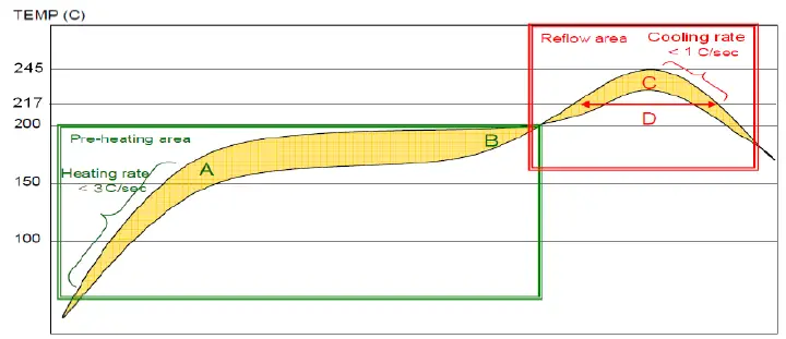
- Solder paste alloy: SAC305 (Sn96.5/Ag3.0/Cu0.5) (Lead Free solder paste.)
- A-B. Temp.: 150~200℃; soak time:60~120sec. (Base on Flux type, reference only)
- C. Peak temp: <245℃
- D. Time above 217 ℃: 40~90sec. (Base on SAC305)
- Suggestion: Optimal cooling rate is <1℃/sec. from peak to 217 ℃.
- Nine heater zones at least for Reflow equipment.
- Nitrogen usage is recommended and be controlled a value less than 1500 ppm. Note: Need to inspect solder joint by X-ray post reflow
Agency Approvals
FCC
Model: SOMAT39
This equipment has been tested and found to comply with the limits for a Class B digital device, pursuant to Part 15 of the FCC Rules. These limits are designed to provide reasonable protection against harmful interference in a residential installation.
This equipment generates, uses and can radiate radio frequency energy. However, there is no guarantee that interference will not occur in a installation. If this equipment does cause harmful interference to radio or reception, which can be determined by turning the equipment off and on, the user is encouraged to try to correct the interference by one or more of the following measures:
- Reorient or relocate the receiving antenna.
- Increase the separation between the equipment and receiver.
- Connect the equipment into an outlet on a circuit different from that to which the receiver is connected.
- Consult the dealer or an experienced technician for help.
This device complies with part 15 of the FCC Rules. Operation is subject to the following two conditions:
- This device may not cause harmful interference, and
- This device must accept any interference received, including interference that my cause undesired operation.
MODIFICATION: Any changes or modifications not expressly approved by the grantee of this device could void the user’s authority to operate the device.
This equipment should be installed and operated with minimum distance 20cm between the radiator and your body.
Industry Canada
Model: SOMAT39 IC: 1693B-HWUSIA
This device complies with Industry Canada RSS standard(s). Operation is subject to the following two conditions:
- this device may not cause interference, and
- this device must accept any interference, including interference that may cause undesired operation of the device.
Changes or modifications not expressly approved by the party responsible for compliance could void the user’s authority to operate the equipment.
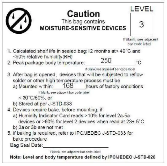
MSL Level / Storage Conditions