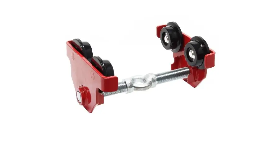
XPOtool 62680 Hand-Geared Crane Trolley

Read and follow the operating instructions and safety information before using for the first time.
Technical changes reserved!
Due to further developments, illustrations, functioning steps, and technical data can differ insignificantly.
Updating the documentation
If you have suggestions for improvement or have found any irregularities, please contact us.
The information contained in this document may alter at any time without previous notice. It is prohibited to copy or spread any parts of this document in any way without prior written allowance. All rights re-served.
The WilTec Wildanger Technik GmbH cannot be held accountable for any possible mistakes in this operating manual, nor in the diagrams and figures shown.
Even though, the WilTec Wildanger Technik GmbH has undergone biggest possible efforts to ensure that the operating manual is complete, faultless, and up to date, mistakes cannot be entirely avoided.
If you should find a mistake or wish to make a suggestion for improvement, we look forward to hearing from you.
Send an e-mail to:
[email protected] or use our contact form:
https://www.wiltec.de/contacts/
The most recent version of this manual in various languages can be found in our online shop via:
https://www.wiltec.de/docsearch
Our postal address is:
WilTec Wildanger Technik GmbH
Königsbenden 12
52249 Eschweiler
Germany
To return orders for exchange, repair, or other purposes, please use the following address. Attention! To allow for a smooth execution of your complaint or return, it is important to contact our customer service team before returning the goods.
Returns Department
WilTec Wildanger Technik GmbH
Königsbenden 28
52249 Eschweiler
E-mail: [email protected]
Tel: +49 2403 55592–0
Fax: +49 2403 55592–1
Introduction
Thank you for purchasing this quality product. To minimise the risk of injury we urge that our clients take some basic safety precautions when using this device. Please read the operation instruc-tions carefully and make sure you have understood its content.
Keep these operation instructions safe.
Safety instructions
Certain tasks and operations must not be performed with this trolley as they might lead to personal injury or property damage.
- The transport of persons is not allowed.
- Do not transport objects above persons’ heads.
- Loads must be lifted vertically. Diagonal pull must not be performed.
- Do not attempt to free jammed loads by tearing at them.
- Do not leave lifted loads unobserved.
- Do not reach into the moving parts.
- It is prohibited to use the trolley to tear objects off, loosen, or pull them horizontally.
- The maximum load capacity of the trolley must not be exceeded.
- Check the trolley for damage and signs of wear before using it. A damaged trolley must not be used and must be repaired by qualified personnel before it can be used again.
- Always make sure the trolley is properly and securely connected to the beam before using it.
- Check the rollers of the trolley before every use. It is important to inspect the side clearance between the rollers and the beam.
- Before using the trolley, always check the screw retention as well as the fastening of the trav-erse.
- The personnel intended to operate the trolley must have read and understood the information and instructions stated within this operation manual and must be familiar with the device before operating it.
- Do not wear loose clothing, jewellery or accessories and make sure to keep long hair tied up or covered by snood-type cap. Loose accessories, clothing, or long hair might get caught in moving parts and cause severe injuries.
- Labels and signs depicting safety instructions must not be removed or garbled. All security in-structions located on the trolley must be kept in readable condition.
Important! The trolley was designed for manual operation and must not be operated with a motor or other means such as a drill.
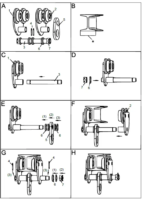
Assembly
- Accurately measure the width of the beam, to which the trolley is supposed to be attached to.
- Equally attach a number of spacers to the inside of the trolley that causes the wheel flanges of the rollers to be 6 mm wider than the width of the beam.
- Mount the remaining spacers to the outside of the plate assemblies and attach matching nuts to the suspension bolt.
- A minimum of 1 spacer must be place on the inside as well as on the outside of every lateral plate (Fig. N).
- Loosen the nuts of the suspension pin and straddle the lateral plates to enable the rollers to effortlessly slide along the beam.
- Tighten the previously loosened nuts and make sure they securely rest against the spacers before attaching a light weight to the trolley to confirm that all the rollers contact the beam. Once again tighten the nuts and secure them with the help of locking devices.
- If mounting the trolley to a beam requiring its minimum width settings, its suspension pin needs to be moved to prevent it from interfering with the movement of the chain.
- Attach the maximum safe working load to the trolley and slowly and carefully move it along the entire beam to check the safety of the track.
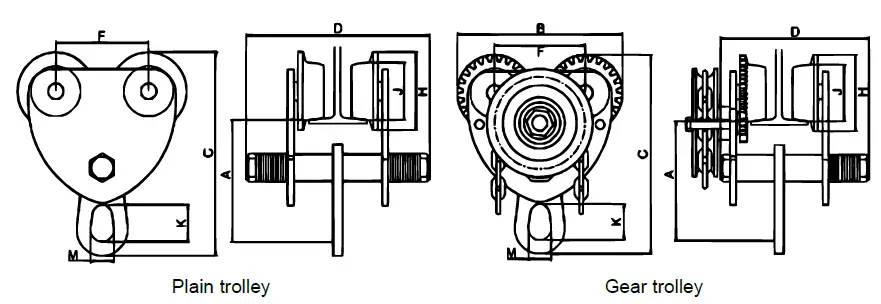
Installation
Plain trolley
Beam width
Gear trolley
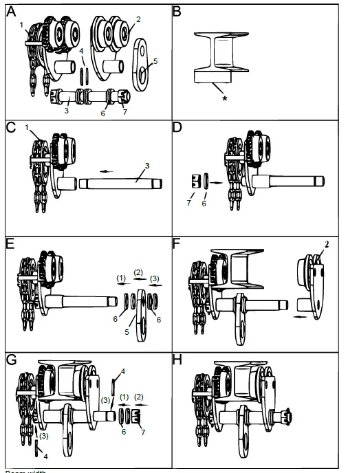
Beam width
Exploded drawing and parts list
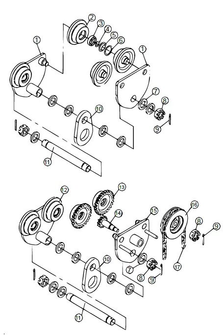
| № | Name | № | Name |
| 1 | Lateral plates | 10 | Suspension plate |
| 2 | Roller | 11 | Suspension pin |
| 3 | Bearing | 12 | Left plate assembly |
| 4 | Circlip | 13 | Pinion |
| 5 | Bearing cover | 14 | Drive screw |
| 6 | Ball bearing race | 15 | Right plate assembly |
| 7 | Spacer | 16 | Sprocket |
| 8 | Hexagonal nut | 17 | Hand chain |
| 9 | Cotter-pin |
Technical Specifications
Plain trolley
| Capac- ity (t) | Recom- mended l- beam width (㎜) | Weight (㎏) | A | B | C | D | E | H | J | K | M | Size (㎜) |
| 0.5 | 75–125 | 4.1 | 112 | 161 | 188 | 198 | 23 | 72 | 52 | 36 | 25.5 | 200 × 79 × 155 |
| 75–180 | 4.2 | 251 | 280 × 75 × 155 | |||||||||
| 1 | 75–125 | 7.3 | 119 | 203 | 214 | 220 | 11 | 91.5 | 69 | 46 | 29 | 210 × 80 × 190 |
| 75–180 | 7.5 | 262 | 250 × 85× 190 | |||||||||
| 2 | 100–150 | 10.7 | 125 | 225 | 228 | 245 | 14 | 102 | 75 | 46 | 30 | 230 × 95 ×195 |
| 100–200 | 11 | 293 | 280 × 105 × 195 | |||||||||
| 3 | 100–150 | 17.4 | 165 | 274 | 304 | 268 | 8 | 122 | 99 | 76 | 46 | 280 × 105 × 245 |
| 100–250 | 18 | 318 | 325 × 110 ×245 | |||||||||
| 5 | 125–175 | 28.3 | 183 | 302 | 334 | 305 | 21 | 141 | 108 | 100 | 44 | 315 × 140 × 320 |
| 125–250 | 29 | 380 | 386 × 140 × 331 | |||||||||
| 10 | 110–200 | 61.2 | 250 | 367 | 434 | 405 | 36 | 174 | 128 | 93 | 63 | 500 × 210 × 350 |
| 110–300 | 62 | 503 |
Gear trolley
| Capac- ity (t) | Recom- mended l- beam width (㎜) | Weight (㎏) | A | B | C | D | E | H | J | K | M | Size (㎜) |
| 0.5 | 75–125 | 8.55 | 112 | 161 | 188 | 198 | 23 | 72 | 52 | 36 | 25.5 | 200 × 79 × 155 |
| 75–180 | 9 | 251 | 280 × 75 × 155 | |||||||||
| 1 | 75–125 | 10.7 | 119 | 203 | 214 | 220 | 11 | 91.5 | 69 | 46 | 29 | 210 × 80 × 190 |
| 75–180 | 11 | 262 | 250 × 85× 190 | |||||||||
| 2 | 100–150 | 14 | 125 | 225 | 228 | 245 | 14 | 102 | 75 | 46 | 30 | 230 × 95 ×195 |
| 100–200 | 14.5 | 293 | 280 × 105 × 195 | |||||||||
| 3 | 100–150 | 21.5 | 165 | 274 | 304 | 268 | 8 | 122 | 99 | 76 | 46 | 280 × 105 × 245 |
| 100–250 | 22 | 318 | 325 × 110 ×245 | |||||||||
| 5 | 125–175 | 32 | 183 | 302 | 334 | 305 | 21 | 141 | 108 | 100 | 44 | 315 × 140 × 320 |
| 125–250 | 33 | 380 | 386 × 140 × 331 | |||||||||
| 10 | 110–200 | 70.4 | 250 | 367 | 434 | 405 | 36 | 174 | 128 | 93 | 63 | 500 × 210 × 350 |
| 110–300 | 71 |
Important note:
Reproduction and any commercial use (of parts) of this operating manual, requires a written permission of WilTec Wildanger Technik GmbH
https://www.XPOtool.com
Item 62680–62682
The Tool Experts


