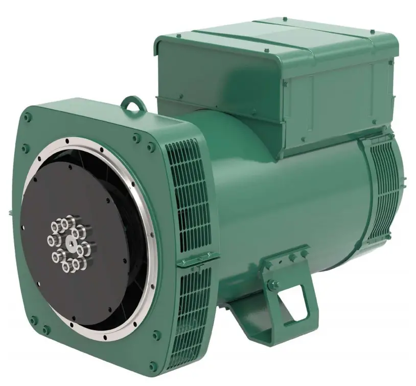
LEROY-SOMER 44.3 Low Voltage Alternator
This manual concerns the alternator which you have just purchased. We wish to draw your attention to the contents of this maintenance manual.
SAFETY MEASURES
Before using your machine for the first time, it is important to read the whole of this installation and maintenance manual.
All necessary operations and interventions on this machine must be performed by a qualified technician.
Our technical support service will be pleased to provide any additional information you may require.
The various operations described in this manual are accompanied by recommendations or symbols to alert the user to potential risks of accidents. It is vital that you understand and take notice of the following warning symbols.
![]()
Warning symbol for an operation capable of damaging or destroying the machine or surrounding equipment.

Warning symbol for general danger to personnel.
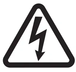
Warning symbol for electrical danger to personnel.
SAFETY INSTRUCTIONS
Sets of self-adhesive stickers depicting the various warning symbols are included with this maintenance manual.
They should be positioned as shown in the drawing below once the machine has been fully installed.
WARNING
The alternators must not be put into service until the machines in which they are to be incorporated have been declared compliant with EC Directives plus any other directives that may be applicable.
This manual is to be given to the end user.
The range of electric alternators and their derivatives, manufactured by us or on our behalf, comply with the technical requirements of the customs Union directives.
The alternator is a sub-assembly delivered without a system of protection against short-circuits. The protection must be provided by the circuit-breaker of the generator, sized to interrupt the fault current.
© 2023 Moteurs Leroy-Somer SAS Share Capital: 32,239,235 €, RCS Angouleme 338 567 258.
We reserve the right to modify the characteristics of this product at any time in order to incorporate the latest technological developments. The information contained in this document may therefore be changed without notice.
This document may not be reproduced in any form without prior authorization.
All brands and models have been registered and patents applied for.
RECEIPT
Standards and safety measures
Our alternators comply with most international standards.
See the EC Declaration of Incorporation on the last page.
Inspection
On receipt of your alternator, check that it has not suffered any damage in transit. If there are obvious signs of knocks, contact the transporter (you may be able to claim on their insurance) and after a visual check, turn the machine by hand to detect any malfunction.
Identification
The alternator is identified by means of a nameplate fixed on the machine (see drawing).
Make sure that the nameplate on the machine conforms to your order.
So that you can identify your alternator quickly and accurately, we suggest you fill in its specifications on the nameplate below.
Prior to commissioning, machines should be stored:
– away from humidity(< 90%); after a long period of storage, check the machine insulation. To prevent the bearings from becoming marked, do not store in an environment with significant vibration.
Applications
This alternator is mainly designed to produce electricity in the context of applications involving the use of generators.
Usage restrictions
Use of the machine is restricted to operating conditions (environment, speed, voltage, power, etc) compatible with the characteristics indicated on the nameplate.

Scan the code or go to
GEN.LS1.DO to check product data
TECHNICAL CHARACTERISTICS
Electrical characteristics
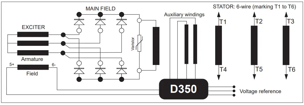
This alternator is a machine without sliprings or revolving armature brushes, wound as “2/3 pitch”, 6-wire, with class H insulation and a field excitation system available in AREP version (see diagram and AVR manual).
- Stator temperature detection sensors
- Space heaters
- R791 interference suppression
- AREP three-phase 6-wire MAIN FIELD
Mechanical characteristics
- Steel frame
- Cast iron end shields
- Ball bearings greasable
- Mounting arrangement: single bearing with standard feet and SAE flanges/ coupling discs, two-bearing with SAE flange and standard cylindrical shaft extension
- Enclosed machine cooled by heat transfer fluid
- Degree of protection: IP 44

Cooling circuit characteristics
- Cooling method: IC7A1W7
- Type offluid: water+ additive
- Operating temperature: 70°C (±5°C)
- Permitted additives: Glycol-type antifreeze
- Maximum level of additives: 50%
- Operating pressure: 3 bar (8 bar maximum)
- pH of water: 7<pH<8
Glycol (or Ethylene glycol) type antifreeze is a hazardous product which is harmful to health.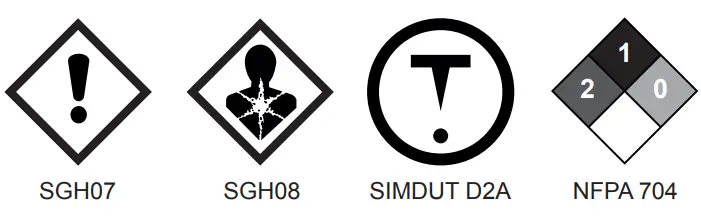
Risks:
- H302: Harmful if swallowed
- H373: May cause damage to organs through prolonged or repeated exposure Precautions:
- P260: Do not breathe fumes/mist/ vapours
- P301: If swallowed:
- P312: Call a poison centre or doctor/ physician if you feel unwell
- P330: Rinse mouth
Never use methanol or isopropanol type antifreeze.
INSTALLATION
Personnel undertaking the various operations indicated in this section must wear personal protective equipment appropriate for mechanical and electrical hazards.
Assembly
All mechanical handling operations must be undertaken using suitable equipment and the machine must be horizontal. Check how much the machine weighs before choosing the lifting tool. During this operation, do not allow anyone to stand under the load.
Handling
The generously-sized lifting eyes are for handling the alternator only. They must not be used to lift the genset. The choice of lifting hooks or handles should be determined by the shape of the lifting eyes. Choose a lifting system which respects the integrity and the environment of the machine.
During this operation, do not allow anyone to stand under the load.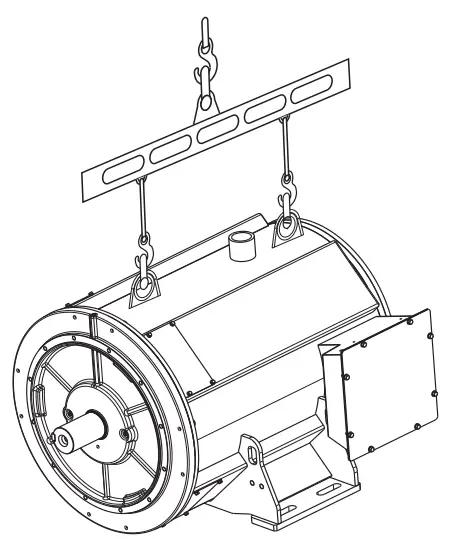
Single-bearing coupling
Before coupling, check the compatibility between the alternator and the engine by performing:
– undertaking a torsional analysis of the transmission (alternators data are available on request),
– checking the dimensions of the flywheel and its housing, the flange, coupling discs and offset.
When coupling the alternator to the prime mover, do not use the fan to turn the alternator or rotor.
The holes of the coupling discs should be aligned with the flywheel holes by cranking the engine.
Make sure the machine is securely bedded in position during coupling.
Check that there is lateral play on the crankshaft.
Double-bearing coupling
– Semi-flexible coupling Careful alignment of the machines is recommended, checking that the lack of concentricity and parallelism of both parts of the coupling do not exceed 0.1 mm.
This alternator has been balanced with a 1/2 key.
Location
The location where the alternator is placed must be ventilated to ensure that the ambient temperature cannot exceed the data on the nameplate.
Checks prior to first use
Electrical checks
Under no circumstances should an alternator, new or otherwise, be operated if the insulation is less than 1 megohm for the stator and 100,000 ohms for the other windings.
There is possible method for restoring the above minimum values, dry out the machine for 24 hours in a drying oven at a temperature of 110 °C.
![]()
Ensure that the alternator has the degree of protection matching the defined environmental conditions.
Mechanical checks
Before starting the machine for the first time, check that:
- top up the cooling circuit with water before starting the machine,
- all fixing screws are tight, and that there are no leaks on the water inlet and outlet,
- the length of screw and the tightening torque are correct,
- the protective grille and housing are correctly in place,
- the standard direction of rotation is clockwise as seen from the drive end (phase rotation in order 1 – 2 – 3).
For anti-clockwise rotation, swap 2 and 3. - the winding connection corresponds to the site operating voltage (see section 3.3).
![]()
At the first start-up or after an extended shutdown, allow the machine to be purged: bleeder (69).
Terminal connection diagrams
The winding code is specified on the nameplate.
Any intervention on the alternator terminals during checks should be performed with the machine stopped. In no case should the internal connections in the terminal box be subjected to stresses due to cables connected by the user.
| Connection codes | Voltage/ Detection | Factory connection | ||
 | Winding | 60 Hz | 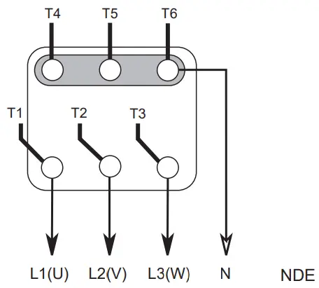 | |
| 6S | 380 – 415 | 380 – 480 | ||
D350: | ||||
Thermistor temperature (PTC) | |
 | 130 °C Blue wire |
| 150 °C Black wire | |
| 180 °C Red/white wire | |
Connection checks
Electrical installations must comply with the current legislation in force in the country of use.
Check that:
- The residual circuit-breaker conforms to legislation on protection of personnel, in force in the country of use, and has been correctly installed on the alternator power output as close as possible to the alternator.
(In this case, disconnect the wire of the interference suppression module linking the neutral). - Any protection devices in place have not been tripped.
- If there is an external AVR, the connections between the alternator and the cabinet are made in accordance with the connection diagram.
- There is no short-circuit phase-phase or phase-neutral between the alternator output terminals and the generator set control cabinet (part of the circuit not protected by circuit breakers or relays in the cabinet).
- The machine should be connected with the busbar separating the terminals as shown in the terminal connection diagram.

- The alternator earth terminal inside the terminal box is connected to the electrical earth circuit
- The earth terminal is connected to the frame.
The connections inside the terminal box must never be subjected to stress due to cables connected by the user.


Commissioning
The machine can only be started up and used if the installation is in accordance with the regulations and instructions defined in this manual.
The machine is tested and set up at the factory. When first used with no load, make sure that the drive speed is correct and stable (see the nameplate). With the regreasable bearing option, we recommend greasing the bearings at the time of commissioning (see section 4.3).
On application of the load, the machine should achieve its rated speed and voltage; however, in the event of abnormal operation, the machine setting can be altered (follow the adjustment procedure in section 3.5). If the machine still operates incorrectly, the cause of the malfunction must be located (see section 4.5).
Setting up
The various adjustments during tests must be made by a qualified engineer.
Ensure that the drive speed specified on the nameplate is reached before commencing adjustment.
After operational testing, replace all access panels or covers.
The AVR is used to make any adjustments to the machine.
SERVICING – MAINTENANCE
Safety measures
Servicing or troubleshooting must be carried out strictly in accordance with instructions so as to avoid the risk of accidents and to maintain the machine in its original state.
All such operations performed on the alternator should be undertaken by personnel trained in the commissioning, servicing and maintenance of electrical and mechanical components, who must wear personal protective equipment appropriate for mechanical and electrical hazards.
Before any intervention on the machine, ensure that it cannot be started by a manual or automatic system and that you have understood the operating principles of the system.
Also check that no liquid is leaking from the cooling circuit.

Warning : During and after running, the alternator will reach temperatures hot enough to cause injury, such as burns.
Routine maintenance
Checks after start-up
After approximately 20 hours of operation, check that all fixing screws on the machine are still tight, plus the general state of the machine and the various electrical connections in the installation.
Electrical servicing
Commercially-available volatile degreasing agents can be used.
![]()
Do not use: trichlorethylene, perchloroethylene, trichloroethane or any alkaline products.
These operations must be performed at a cleaning station, equipped with a vacuum system that collects and flushes out the products used.
The insulating components and the impregnation system are not at risk of damage from solvents. Avoid letting the cleaning product run into the slots. Apply the product with a brush, sponging frequently to avoid accumulation in the housing. Dry the winding with a dry cloth. Let any traces evaporate before reassembling the machine.
Mechanical servicing
![]()
Cleaning the machine using water or a high-pressure washer is strictly prohibited. Any problems arising from such treatment are not covered by our warranty.
Check regularly that no liquid is leaking from the cooling circuit.
Degreasing: Use a brush and detergent (suitable for paintwork).
Dusting: Use an air gun.
If the machine is fitted with air inlet and outlet filters, the maintenance personnel should clean them routinely at regular intervals. In the case of dry dust, the filter can be cleaned using compressed air and/or replaced if it is clogged.
After cleaning the alternator, it is essential to check the winding insulation (see sections 3.2 and 4.5).
Bearings
| The bearings are greasable |
|
Cooling circuit
| Composition | Water, anticorrosion oxygen inhibitor, glycol-type antifreeze up to 50% |
| Maintenance |
|
Mechanical defects
Fault | Action | |
| Bearing | Excessive overheating of one or both bearings (bearing temperature 80°C above the ambient temperature) | If the bearing has turned blue or if the grease has turned black, change the bearing.
|
| Abnormal temperature | Excessive overheating of alternator frame (more than 40° C above the ambient temperature) |
|
| Vibrations | Too much vibration |
|
| Excessive vibration and humming noise coming from the machine |
| |
| Abnormal noise | Alternator damaged by a significant impact, followed by humming and vibration |
|
Electrical faults
| Fault | Action | Effect | Check/Cause |
| No voltage at no load on start-up | Connect a new battery of 4 to 12 volts to terminals E-and E+, respecting the polarity, for 2 to 3 seconds | The alternator builds up and its voltage is still correct when the battery is removed |
|
| The alternator builds up but its voltage does not reach the rated value when the battery is removed |
| ||
| The alternator builds up but its voltage disappears when the battery is removed |
| ||
| Voltage too low | Check the drive speed | Correct speed | Check theAVR connections (AVR may be faulty)
|
| Speed too low | Increase the drive speed (do not touch the AVR voltage pot. (P2) before running at the correct speed) | ||
| Voltage too high | AdjustAVR voltage potentiometer | Adjustment ineffective |
|
| Voltage oscillations | Adjust the AVR stability potentiometer | If no effect: try normal or fast stability modes (ST2) | Check the speed: possibility of cyclic irregularity
|
| Voltage correct at no load and too low when on load | Run at no load and check the voltage between E+ and E-on the AVR | Voltage between E+ and E- (DC) AREP < 10V |
|
| Voltage between E+ and E- AREP > 15V |
| ||
| Voltage disappears during operation | Check the AVR, the surge suppressor, the rotating diodes, and replace any defective components | The voltage does not return to the rated value |
|
Checking the winding
You can check the winding insulation by performing a high voltage test. In this case, you must disconnect all AVR wires.
![]()
Damage caused to the AVR in such conditions is not covered by our warranty.
- Checking the diode bridge
A diode in good working order should allow the current to flow only in the anode-to cathode direction.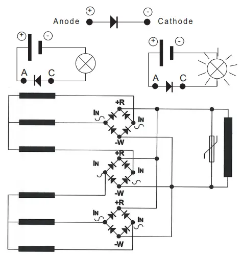
- Checking the windings and rotating diodes using separate excitation
During this procedure, make sure that the alternator is disconnected from any external load and inspect the terminal box to check that the connections are fully tightened.
- Stop the unit, disconnect and isolate the AVR wires.
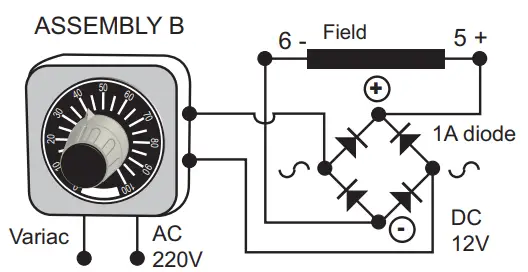
- There are two ways of creating an assembly with separate excitation.
Assembly A: Connect a 12 V battery in series with a rheostat of approximately 50 ohms – 300 W and a diode on both exciter field wires (5+) and (6-)
Assembly B: Connect a “Variac” variable power supply and a diode bridge on both exciter field wires (5+) and (6-).
Both these systems should have characteristics which are compatible with the field excitation power of the machine (see the nameplate). - Run the unit at its rated speed.
- Gradually increase the exciter field current by adjusting the rheostat or the variac and measure the output voltages on L1 – L2 – L3, checking the excitation voltage and current at no load (see the machine nameplate or ask for the factory test report).
When the output voltage is at its rated value and balanced within 1% for the rated excitation level, the machine is in good working order. The fault therefore comes from the AVR or its associated wiring (ie. sensing, auxiliary windings).

Dismantling, reassembly
During the warranty period, this operation should only be carried out in an approved workshop or in our factory, otherwise the warranty may be invalidated.
Whilst being handled, the machine should remain horizontal (rotor not locked when moved). Check how much the machine weighs before choosing the lifting method.
Tools required
To fully dismantle the machine, we recommend using the tools listed below:
- 1 ratchet spanner + extension
- 1 torque wrench
- 1 set of flat spanners: 7, 8, 10, 12 mm
- 1 socket set: 8, 10, 13, 16, 18, 21, 22, 24 mm
- 1 Allen key: size 5 (eg. Facom: ET5), size 6 (ET6), size 10 (ET10, size 14 (ET14)
- 1 socket TORX bit T20 and T30
- 1 puller (U35)/(U32/350)
Screw tightening torque
See section 5.4.
Draining the cooling circuit
- Leave the machine stationary for 6 hours before draining the cooling circuit (operating temperature 70°C).
- The cooling circuit must be drained using a fluid recovery system.
Toxic risk
The coolant can contain up to 50% glycol-type antifreeze, which represents a risk to health.
Access to diodes
- Remove the access door (111).
- Check all modules using an ohmmeter or a battery lamp.
- Refit the modules.
- Refit the access door (111).
Access to connections
Access is directly after removing the cover (136).
Replacing the NDE bearing Dismantling
- Remove the inner bearing retainer (78) screws.
- Remove the screws and the NDE bracket (36) using a puller: eg. U.32 – 350 (Facom). – Remove the antifriction bearing (70) using a screw puller.

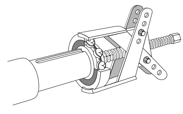
Reassembly
- Heat the inner slipring of a new bearing by induction or in a drying oven at 80°C (do not use an oil bath) and fit it to the machine.
- Place the preloading wavy washer (79) in the bracket and fit a new O ring seal (349).
- To facilitate mounting, screw two threaded rods into inner bearing retainer (78) and slide them into the holes of the bracket by reassembling the NDE bracket (36).
- Finish the assembly of inner bearing retainer (78), unscrew the threaded rod, replace it with the inner bearing retainer (78) screws and the NDE bracket (36) screws, and lock them.


![]()
When dismantling the brackets, you will need to change the antifriction bearings, the “O” ring seal, the preloading (wavy) washer and adhesive paste.
Replacing the DE bearing
Dismantling
- Remove the inner bearing retainer (68) screws.
- Remove the DE bracket (30) screws.
- Remove the DE bracket (30) using a puller: eg. U.32 – 350 (Facom).
- Remove the antifriction bearing (60) using a screw puller.

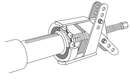
Reassembly
- Heat the inner slipring of a new bearing by induction or in a drying oven at 80°C (do not use an oil bath) and fit it to the machine.
- To facilitate mounting, screw two threaded rods into inner bearing retainer (68) and slide them into the holes of the bracket by reassembling the DE bracket (30).
- Finish the assembly of inner bearing retainer (68), unscrew the threaded rod, replace it with the inner bearing retainer (68) screws and the DE bracket (30) screws, and lock them.
Accessing the revolving field coil and stator
Dismantling
Follow the procedure for dismantling the bearings.
- Insert a tube of the corresponding diameter on the shaft end.
- Rest the rotor on one of its poles, then slide it out. Use the tube as a lever arm to assist dismantling.
- After extraction of the rotor, be careful not to damage the fan or dismantle it.
- Remove the revolving field coil and place on special V-shaped supports.
NOTE: If intervention is required on the revolving field coil (rewinding, replacement of components), the rotor assembly must be rebalanced.
Reassembling the revolving field coil
- Follow the dismantling procedure in reverse order.
Take care not to knock the windings when refitting the rotor in the stator. - Refit the fan with its fixing screws on the hub.
Follow the procedure for refitting the bearings.
Table of characteristics
Table of average values:
Alternator – 4 poles – 50 Hz – Standard winding No. 6S (6-wire)
The voltage and current values are given for no-load operation and operation at rated load with separate field excitation.
All values are given to within ± 10% and may be changed without prior notification (for exact values, consult the test report).
Three-phase: 4 pole AREP excitation Resistances at 20 °C (Ω)
| Type | Stator LIN | Rotor | Exciter field | Exciter armature |
| M4 | 0.021 | 2.64 | 8.07 | 0.920 |
| M6 | 0.022 | 2.89 | 8.07 | 0.920 |
| L8 | 0.015 | 3.15 | 8.07 | 0.920 |
| VL12 | 0.010 | 3.86 | 8.07 | 0.920 |
Resistances of auxiliary windings at 20 °C (Ω)
| Type | X1, X2 | Z1, Z2 |
| M4 | 0.300 | 0.552 |
| M6 | 0.283 | 0.553 |
| L8 | 0.265 | 0.536 |
| VL12 | 0.272 | 0.591 |
Field excitation current i exc (A) 400V – 50 Hz
“i exc”: excitation current of the exciter field
| Type | No load | At rated load |
| M4 | 1.08 | 1.40 |
| M6 | 0.74 | 1.35 |
| L8 | 0.94 | 1.42 |
| VL12 | 0.94 | 1.39 |
For 60 Hz machines, the “i exc” values are approximately 5 to 10 % lower.
Table of weights
(values given for information only)
| Type | Total weight (kg) | Rotor (kg) |
| M4 | 545 | 135.5 |
| M6 | 580 | 147 |
| L8 | 622 | 160.5 |
| VL12 | 750 | 206 |
After operational testing, it is essential to replace all access panels or covers.
SPARE PARTS
First maintenance parts
Here is the list of parts:
| Single bearing kit | 5336683 |
| Non drive end bearing RLT040OU030 Preloading (wavy) washer 0 ring seal | |
| Two-bearing kit | 5194748 |
| Drive end bearing RLT070OU030 Non drive end bearing RLT040OU030 Preloading (wavy) washer O ring seal Circlips | |
| Diode bridge kit | 4888595 |
| Surge suppressor | 4691059 |
| AVR AREP D350 | 5124059 |
| AVR AREP D550 | 5157122 |
Technical support service
Our technical support service will be pleased to provide any additional information you may require.
For all spare parts orders or technical support requests, send your request to [email protected] or your nearest contact, whom you will find at www.lrsm.co/support indicating the complete type of machine, its number and the information indicated on the nameplate.
Part numbers should be identified from the exploded views and their description from the parts list.
To ensure that our products operate correctly and safely, we recommend the use of original manufacturer spare parts. In the event of failure to comply with this advice, the manufacturer cannot be held responsible for any damage.
After operational testing, it is essential to replace all access panels or covers.
Accessories
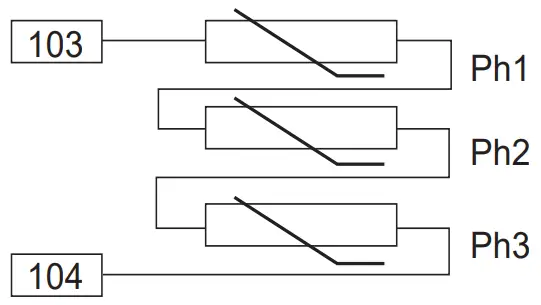
Temperature sensors with thermistors (PTC)
These are thermistor triplets with a positive temperature coefficient installed in the stator winding (1 per phase). There can be a maximum of 2 triplets in the winding (at 2 levels: warning and trip) and 1 or 2 thermistors in the shields.
These sensors must be linked to adapted sensing relays (supplied optionally).
Cold resistance of cold thermistor sensors: 100 to 250 Ω per sensor.
Exploded views, parts list and tightening torque
Single bearing

Two-bearing

| Ref. | Qty | Description | Screw 0 | Torque N.m | Ref. | Qty | Description | Screw 0 | Torque N.m |
| 1 | 1 | Stator assembly | – | – | 79 | 1 | Preloading (wavy) washer | – | – |
| 2 | 4 | Air duct cover | M6 | 10 | 90 | 1 | Exciter field (stator) | M6 | 8.3 |
| 4 | 1 | Rotor assembly | – | – | 100 | 1 | Exciter armature (rotor) | – | – |
| 15 | 1 | Fan | M6 | 5 | 107 | 1 | Diode bridge support | MS | 6 |
| 22 | 1 | Shaft extension key | – | – | 111 | 1 | Diode access door | M6 | 10 |
| 28 | 1 | Earth terminal | M10 | 20 | 124 | 1 | Terminal block | M6 | 10 |
| 30 | 1 | Drive end (DE) flange (single bearing) or drive end (DE) bracket (two-bearing) | M10 | 40 | 129 | 1 | Auxiliary terminal block | M3 | 1 |
| 36 | 1 | Non drive end (NOE) bracket | M10 | 40 | 132 | 1 | Terminal box body | M6 | 10 |
| 53 | 1 | Sealing cap | M6 | 8.3 | 136 | 1 | Terminal box cover | M6 | 10 |
| 60 | 1 | Drive end (DE) bearing | – | – | 198 | 1 | Voltage regulator (AVR) | MS | 6 |
| 67 | 1 | Circlips | – | – | 320 | 1 | Coupling sleeve | – | – |
| 68 | 1 | Inner bearing retainer | M6 | 8.3 | 322 | 2 | Coupling disc | M16 | 300 |
| 69 | 1 | Bleeder | – | – | 343 | 3 | Diode bridge | MS | 3 |
| 70 | 1 | Non drive end (NOE) bearing | – | – | 347 | 1 | Surge suppressor (+ PCB) | M6 | 4 |
| 77 | 2 | Grease nipple | MS | 20 | 349 | 1 | 0 ring seal | – | – |
| 78 | 1 | Inner bearing retainer | M6 | 8.3 |
Disposal and recycling instructions
We are committed to limiting the environmental impact of our activity. We continuously monitor our production processes, material sourcing and product design to improve recyclability and minimise our environmental footprint.
These instructions are for information purposes only. It is the user’s responsibility to comply with local legislation regarding product disposal and recycling.
Recyclable materials
Our alternators are mainly constructed from iron, steel and copper materials, which can be reclaimed for recycling purposes. These materials can be reclaimed through a combination of manual dismantling, mechanical separation and melting processes. Our technical support department can provide detailed directions on how to dismantle products on request.
Waste & hazardous materials
The following components and materials require special treatment and must be separated from the alternator before the recycling process:
- electronic materials found in the terminal box, including the automatic voltage regulator (198), current transformers (176), interference suppression module and other semi-conductors.
- diode bridge (343) and surge suppressor (347), found on the alternator rotor.
- major plastic components, such as the terminal box structure on some products. These components are usually marked with information concerning the type of plastic.
All materials listed above need special treatment to separate waste from reclaimable materials and should be entrusted to specialist recycling companies.
The coolant, oil and grease from the lubrication system should be treated as hazardous waste and must be treated in accordance with local legislation.
Our alternators have a specified lifetime of 20 years. After this period, the operation of the product should be stopped, regardless of its condition. Any further operation after this period will be under the sole responsibility of the user.
EC Declaration
Moteurs Leroy-Somer
Boulevard Marcellin Leroy – CS 10015
16915 Angoulême cedex 9 – France
4152 en – 2021.10 / v
Angoulême, 28 October 2021
EC Declaration
Moteurs Leroy-Somer declares hereby that the electric generators of the types:
LSA 40 – LSA 42.3 – LSA 44.3 – LSA 46.3 – LSA 47.2 – LSA 47.3 – LSA 49.1 – LSA 49.3 – LSA 50.1 – LSA 50.2 – LSA 51.2 – LSA 52.2 – LSA 52.3 – LSA 53 – LSA 53.1 – LSA 53.2 – LSA 54 – LSA 54.2 – TAL 040 – TAL 042 – TAL 044 – TAL 046 – TAL 047 – TAL 0473 – TAL 049 – LSAH 42.3 – LSAH 44.3 as well as their derivatives, manufactured by Leroy-Somer or on Leroy-Somer’s behalf:
| MOTEURS LEROY-SOMER Boulevard Marcellin Leroy 16015 Angoulême France | MLS HOLICE STLO.SRO Sladkovskeho 43 772 04 Olomouc République Tchèque | MOTEURS LEROY-SOMER 1, rue de la Burelle Boite Postale 1517 45800 St Jean de Braye France |
| LEROY-SOMER ELECTROTECHNIQUE Co., Ltd No1 Aimosheng Road, Galshan Town, Cangshan District. Fuzhou, Fujian 350026 Chine | NIDEC INDUSTRIAL AUTOMATION INDIA PRIVATE Ltd – BANGALORE #45, Nagarur, Huskur Road Off Tumkur Road, Bengaluru-562 162 Inde | NIDEC INDUSTRIAL AUTOMATION INDIA PRIVATE Ltd – HUBLI #64/A, Main Road, Tarihal IndustrialArea, Tarihal, Hubli-580 026 Inde |
meet the requirements of the following standards and directives
Declaration of compliance:
- Low Voltage Directive Nr 2014/35/EU dated 26th February 2014.
- EN and IEC 60034-1, 60034-5 and 60034-22.
- ISO 8528-3 “Reciprocating internal combustion engine driven alternating current generating sets. Part
3. Alternating current generators for generating sets”. These generators also comply with the ROHS Directive Nr 2011/65/EU dated 8th June 2011 and its Annex II Nr 2015/863 dated 31st March 2015, as well as the EMC Directive Nr 2014/30/EU dated 26th February 2014.
Declaration of incorporation:
These generators are designed to meet the essential requirements Annex I, chapters 1.1.2, 1.1.3, 1.1.5, 1.3.1 to 1.3.3, 1.3.6 to 1.3.8.1, 1.4.1, 1.4.2.1, 1.5.2 to 1.5.11, 1.5.13, 1.6.1, 1.6.4, 1.7 (except 1.7.1.2) of Machinery Directive Nr 2006/42/EC, as well as Annex VII, part B of this directive and the aforementioned standards.
As a result, these “Partly completed machinery” are designed to be incorporated into Electrical Gen-Sets complying with the Machinery Directive Nr 2006/42/EC dated 17th May 2006.
WARNING:
The here mentioned generators should not be commissioned until the corresponding Gen-Sets have been declared in compliance with the Directives Nr 2006/42/EC, 2014/30/EU, 2011/65/EU and 2015/863, as well as with other relevant Directives.
Moteurs Leroy-Somer undertakes to transmit, in response to a reasoned request by the national authorities, relevant information on the generator.
J.P. CHARPENTIER – Y. MESSIN
The contractual EC Declaration of compliance and incorporation can be obtained from your contact on request.
Service & Support
Our worldwide service network of over 80 facilities is at your service.
This local presence is our guarantee for fast and efficient repair, support and maintenance services.
Trust your alternator maintenance and support to electric power generation experts. Our field personnel are 100% qualified and fully trained to operate in all environments and on all machine types.
We have a deep understanding of alternator operation, providing the best value service to optimise your cost of ownership.

Scan the code or go to:
www.lrsm.co/support
Customer Service
Contact us:
Americas: +1 (507) 625 4011
EMEA: +33 238 609 908
Asia Pacific: +65 6250 8488
China: +86 591 8837 3010
India: +91 806 726 4867
![]() [email protected]
[email protected]
Connect with us at:![]()