GE GN75ENSRSA Outdoor Tankless Water Heater
WARNING: Read entire manual. Failure to follow all guides and rules could cause personal injury or property damage.
- Check with your state and/or local public works department for plumbing codes. You must follow their guides as you install the Water Heater.
NOTE: Failure to comply with these installation instructions will void the product warranty, and the installer will be responsible for any service, repair or damages caused thereby.
BEFORE BEGINNING INSTALLATION
Read these instructions completely and carefully.
- IMPORTANT — Save these instructions for local inspector’s use.
- IMPORTANT — Observe all governing codes and ordinances.
- Note to Installer – Be sure to leave these instructions with the Consumer.
- Note to Consumer – Keep these instructions for future reference.
- Proper installation is the responsibility of the installer.
- Product failure due to improper installation is not covered under the Warranty.
Recognize this symbol as an indication of Important Safety Information!
SAFETY PRECAUTIONS
WARNING: If the information in these instructions is not followed exactly, a fire or explosion may result, causing property damage, personal injury or death.
FOR YOUR SAFETY!
- Do not store or use gasoline or other flammable vapors or liquids or other combustible materials in the vicinity of this or any other appliance. To do so may result in an explosion or fire.
- WHAT TO DO IF YOU SMELL GAS
- Do not try to light any appliance.
- Do not touch any electrical switch;
do not use any phone in your building. - Immediately call your gas supplier from a neighbor’s phone. Follow the gas supplier’s instructions.
- If you cannot reach your gas supplier,
call the fire department. - Do not return to your home until authorized by the gas supplier or fire department.
- Improper installation, adjustment, alteration, service or maintenance can cause property damage, personal injury or death. Refer to this manual. Installation and service must be performed by a qualified installer, service agency or gas supplier.
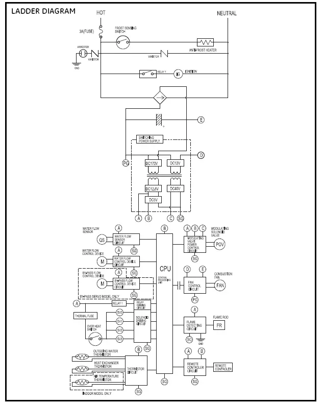
- Service information and wiring diagram are located behind the front panel.
- Service must be performed by a qualified service agency.
- This appliance must be properly grounded and installed as described in these instructions.
DANGER Read and follow water heater warnings and instructions. If the owner’s manual is missing, contact the retailer or manufacturer.
WARNING: Gasoline, as well as other flammable materials and liquids (adhesives, solvents, paint thinners, etc.) and the vapors they produce, are extremely dangerous. DO NOT handle, use or store gasoline or other flammable or combustible materials anywhere near or in the vicinity of a water heater or any other appliance. Be sure to read and follow the labels on the water heater, as well as the warnings printed in this manual. Failure to do so can result in property damage, bodily injury or death.
WARNING: Do not use substitute materials. Use only parts certified with the appliance.
- This appliance must be installed, inspected and leak-tested by a state- and city-qualified licensed contractor. It is the responsibility of the person having the water heater installed to ensure the installing contractor has proper licenses and permits for installing water heaters in your location. GE highly recommends that installers attend a product knowledge class to ensure customer satisfaction and warranty coverage. Failure to comply with state and local codes pertaining to water heater installations may void the warranty.
- This appliance is not to be installed indoors.
- The installation must conform with local codes or, in the absence of local codes, with the National Fuel Gas Code, ANSI Z223.1/NFPA 54, or the Natural Gas and Propane Installation Code, CSA B149.1.
- The appliance and its appliance main gas valve must be disconnected from the gas supply piping system during any pressure testing of that system at test pressures in excess of 1/2 psi (3.5 kPa) (13.84 in W.C.).
- The appliance must be isolated from the gas supply piping system by closing its individual manual shut-off valve during any pressure testing of the gas supply piping system at test pressures equal to or less than 1/2 psi (3.5 kPa)(13.84 in W.C.).
- The appliance should be located in an area where water leakage of the unit or connections will not result in damage to the area adjacent to the appliance or lower floors of the structure. When such locations cannot be avoided,
it is recommended that a suitable drain pan, adequately drained, be installed under the appliance. The pan must not restrict combustion airflow. - The flow of combustion and ventilation air shall not be obstructed.
- This appliance is not suitable for use in an application such as a pool or spa heater that uses chemically treated water. (This appliance is suitable for filling large or whirlpool bathtubs with potable water.)
- If a water heater is installed in a closed-water supply system, such as one having a backflow preventer in the cold water supply line, means shall be provided to control thermal expansion. Contact the water supplier or local plumbing inspector on how to control this situation.
- Should overheating occur or the gas supply fail to shut off, turn off the manual gas control valve to the appliance.
- Keep the air intake location free of chemicals, such as chlorine or bleach, that produce fumes. These fumes can damage components and reduce the life of your appliance.
CAUTION: DO NOT operate the water heater if any part of the appliance has been under water.
CAUTION: BURN HAZARD. Hot exhaust and vent may cause serious burns. Keep back from the water heater unit. Keep small children and animals away from unit.
CAUTION: Hot Water outlet pipes leaving the unit can be hot to the touch. Insulation must be used
for hot water pipes below 36″ due to burning risk to children.
WARNING: This unit is not intended or qualified for use in manufactured homes, mobile homes or recreational vehicles.
Installation Instructions
PARTS PROVIDED
Locate the parts packed with the Water Heater. 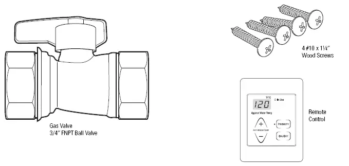
TOOLS YOU WILL NEED
- Pipe Wrenches (2)
- Adjustable Pliers
- Screwdrivers (2)
- Wire Cutters
- Gloves
- Safety Glasses
MATERIALS YOU WILL NEED TO SUPPLY
- Soap Solution
- Pipe Compound
- 5/8″ ID PVC Flexible Tubing
- 2 Conductor 22 AWG
Wire for Remote Control - Single Gang Electrical Box
- Wire Nuts
- Outdoor Rated Switch and Enclosure
- Concrete Wall Anchors (Optional)
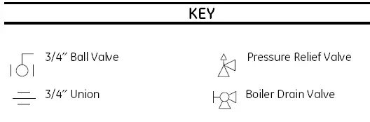
- 3/4 Pipe Fittings Required:
- Unions
- Ball Valves
- Drain Valves
- Pressure Relief Valve
Your installation components may vary.
OTHER TOOLS THAT MIGHT BE REQUIRED
- Hammer Drill with Concrete Bits
- Saw
- Threading Machine with Heads and Oiler
- Core Drill with Diamond Head
- Torch Set
- Copper Tubing Cutter
- Steel Pipe Cutter
OTHER MATERIALS THAT MIGHT BE NEEDED
- Heat Tape
- Pipe Insulation
- Electrical Wire and Conduit per Local Code
- Air Inlet Screen
- Optional Pipe Cover AGTPCM
- Optional Additional Remote Controller AGTRC1
DIMENSIONS
| DIM. | DESCRIPTION | GN75/GN94/GP94ENSRSA IN. (MM) |
| A | Width | 14 (355.6) |
| B | Depth | 913⁄ 16 (249.5) |
| C | Height – Unit | 227⁄ 8 (582) |
| D | Height – with brackets | 253⁄ 8 (646.4) |
| E | Hot Water Outlet – from wall | 313⁄ 16 (96) |
| F | Hot Water Outlet – from center | 45⁄ 16 (110) |
| G | Cold Water Inlet – from wall | 3 (75) |
| H | Cold Water Inlet – from center | 11⁄ 8 (27) |
| I | Gas Connection – from wall | 41⁄ 8 (104) |
| J | Gas Connection – from center | 31⁄ 2 (89) |
| K | From base to gas connection | 15⁄ 8 (40) |
| From base to cold connection | 2 (50) | |
| From base to hot connection | 15⁄ 8 (41) | |
| L | From the bottom of the unit to the bottom of the exhaust | 193⁄ 4 (501.65) |
FLUE TERMINAL CLEARANCES
|
REF |
DESCRIPTION | U.S. INSTALLATIONS CLEARANCES PER ANSI Z21.10.3 |
| A | Clearance above grade, veranda, porch, deck or snowline | 36 inches (91 cm) |
| B | Clearance to window or door that may be opened | 12 inches (30 cm) |
| C | Clearance to permanently closed window | * |
| D | Vertical clearance to ventilated soffit, located above the terminal within a horizontal distance of 2 feet (61 cm) from the center line of the terminal | * |
| E | Clearance to unventilated soffit | * |
| F | Clearance to outside corner | * |
| G | Clearance to inside corner | * |
| H | Clearance to each side of center line extended above meter/regulator assembly | * |
| I | Clearance to service regulator vent outlet | * |
| J | Clearance to nonmechanical air supply inlet to building or the combustion air inlet to any other appliance | 12 inches (30 cm) |
| K | Clearance to a mechanical air supply inlet | 3 feet (91 cm) above if within 10 feet (3 m) horizontally |
| L | Clearance above paved sidewalk or paved driveway located on public property1 | * |
| M | Clearance under veranda, porch, deck or balcony2 | * |
For clearances not specified in ANSI Z223.1/NFPA 54, clearances are in accordance with local installation codes and the requirements of the gas supplier. Clearance to the opposite wall is 24 inches (60 cm).
- A vent shall not terminate directly above a sidewalk or paved driveway that is located between two single-family dwellings and serves both
dwellings. - Permitted only if the veranda, porch, deck or balcony is fully open on a minimum of two sides beneath the floor.
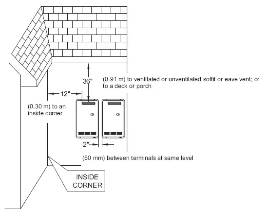
FLUE TERMINAL CLEARANCES (ANSI Z21.10.3 • CSA 4.3)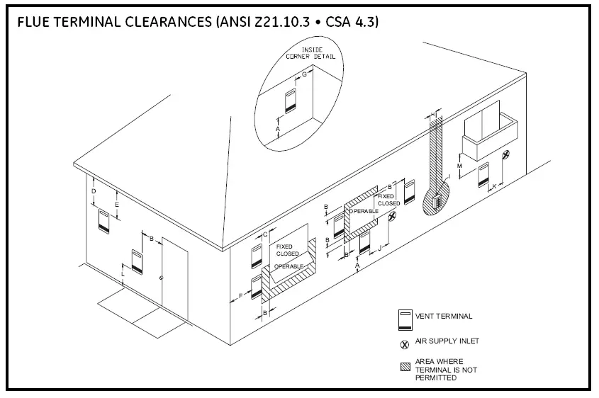
ADDITIONAL CLEARANCES – VENT TERMINAL
Local codes supersede these clearances.
- Avoid termination locations near a dryer vent.
- Avoid termination locations near the commercial cooking exhaust.

PLANNING FOR PLUMBING
(shown with optional pipe cover)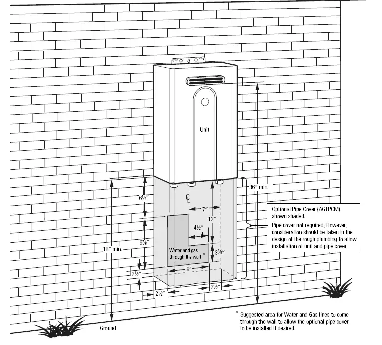
The center of the pipes can be placed anywhere within the shaded area. The center of the pipes is recommended to be protruding only within 6″ of the mounting wall. Other specific installations may be different.
Be sure that the minimum elevation of the bottom of the unit is 18″ to meet the 36″ recommended clearance for the exhaust.
CAUTION: BURN HAZARD. Hot exhaust and vent may cause serious burns. Keep back from water heater unit. Keep small children and animals away from the unit.
CAUTION: Hot Water outlet pipes leaving unit can be hot to the touch. Insulation must be used for hot water pipes below 36″ due to burn risk to children.
NOTE: It is recommended to install the bottom of the unit at least 18″ off the ground to minimize blockage and maintenance from debris and provide room for the optional Pipe Cover Accessory Model Number AGTPCM.
NOTE: Do not install an electrical outlet directly below the unit. The electrical outlet must be installed less than 6 feet from unit.
CLEARANCES FOR WATER HEATER
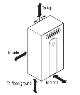
| To combustibles | To noncombustible | |
| Top of heater | 12 inches (305 mm) | 2 inches (51 mm) |
| Back of heater | 0 (zero) | 0 (zero) |
| Front of heater | 24 inches (610 mm) | 24 inches (610 mm) |
| Sides of heater | 6 inches (152 mm) | 1/8 inch (3 mm) |
| Floor/ground | 12 inches (305 mm) | 2 inches (51 mm) |
COMBUSTIBLE MATERIAL: As pertaining
to materials adjacent to or in contact with heat-producing appliances, vent connectors, gas vents, chimneys, steam, and hot water pipes and warm air ducts, shall mean materials made of or surfaced with wood, compressed paper, plant fibers or other materials that are capable of being ignited and burned. Such material shall be considered combustible even though flame-proofed, fire-retardant-treated or plastered.
CORROSIVE ATMOSPHERES
NOTICE: The water heater or intake air supply should not be installed near an air supply containing halogenated hydrocarbons
or near swimming pool chemicals.
MOUNTING THE WATER HEATER
CAUTION: Reinforcement of the wall is required in case the wall is not strong enough to hold the water heater. Do not mount to drywall unless mounting screws are secured in wall studs.
Make sure the location of the water heater allows for easy access and operation.
Wall studs should be utilized when mounting the water heater to the wall. On masonry or concrete wall, use concrete anchors or lag bolts.
MOUNTING THE WATER HEATER (cont.)
- Identify the installation location and confirm that the installation will meet all required clearances. Use the mounting template to locate screw or anchor locations.
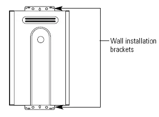
- Securely attach the water heater to the wall using the brackets located at the top and bottom of the water heater.
- Ensure that the attachment strength is sufficient to support the weight. Refer to the weight of the water heater in the Specification Guidelines. Four mounting screws with 200 lb tensile load capacity are required at a minimum

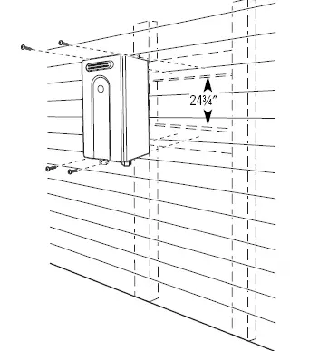
- ON WOOD OR SIDING: When attaching
the unit to wood or siding, mount 2 boards suitable for anchoring to wall studs, between the studs. You can do this before the wall has been finished.
NOTE: Do not hang the unit on wood or siding only. The unit must be secured to studs.
NOTE: Screws provided must fasten securely and directly into wood. If screws go through siding or insulation and do not fully engage, installer must supply the correct screws.
ON MASONRY OR CEMENT WALL: Mount
4 wall anchors (not supplied) suitable to carry 200 lbs minimum tensile load each. Level the unit during installation. IMPORTANT: Anchors suitable for masonry or concrete are to be supplied by the installer. 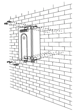
CONNECTING THE WATER HEATER TO GAS AND WATER
GAS PIPING
GENERAL INSTRUCTIONS
- Make sure gas supply is off prior to making any connections to the water heater. A manual gas control valve, provided with this water heater, must be placed in the gas supply line
to the water heater. A union can be used on the connection above the shut-off valve for future servicing or disconnection of the unit. - Check the type of gas and the gas inlet pressure before connecting the water heater. If the water heater is not of the gas type that the building is supplied with, DO NOT connect the water heater. Contact the dealer for the proper unit to match the gas type.
- Check the gas supply pressure immediately upstream at a location provided by the gas company. Supplied gas pressure must be within the limits shown in the Specifications section.
- Before placing the appliance in operation, all joints, including the heater, must be checked for gas tightness by means of leak detector solution, soap and water or an equivalent nonflammable solution, as applicable. (Since some leak test solutions, including soap and water, may cause corrosion or stress cracking, the piping shall
be rinsed with water after testing, unless it has been determined that the leak test solution is noncorrosive.) - Always use approved connectors to connect the unit to the gas line. Always purge the gas line of any debris before connection to the water heater.
- The gas supply line shall be gas-tight, sized
and so installed as to provide a supply of gas sufficient to meet the maximum demand of the heater and all other gas-consuming appliances at the location without loss of pressure. - Any compound used on the threaded joint of the gas piping shall be a type that resists the action of liquefied petroleum gas (propane/LPG).
- Refer to an approved pipe sizing chart
if in doubt about the size of the gas line.
PIPE SIZING PROCEDURE
The gas supply to the home must be capable of handling the entire gas load of the home, calculated by adding the BTU rating of each gas appliance in the home. State and local codes must be met, as well as utility requirements, to ensure gas supply to the unit is adequate to meet the rated demand. Use the charts below as a guide to size the pipe from the utility meter to the tankless water heater. Gas line sizing is based on gas type, the pressure drop in the system, the gas pressure supplied and the gas line type. Refer to the National Fuel Gas Code, NFPA 54, and/or your local gas provider, for proper gas line sizing.
PIPE SIZING TABLE NATURAL GAS
| PIPE SIZING TABLE – NATURAL GAS cubic feet per hour Schedule 40 Metallic Pipe Inlet Pressure: less than 2 psi (55 inches W.C.) Pressure Drop: 0.3 inches W.C. Specific Gravity: 0.60 | ||||
| Length | PIPE SIZE (INCHES) | |||
| 3/4 | 1 | 11/4 | 11/2 | |
| 10 | 273 | 514 | 1060 | 1580 |
| 20 | 188 | 353 | 726 | 1090 |
| 30 | 151 | 284 | 583 | 873 |
| 40 | 129 | 243 | 499 | 747 |
| 50 | 114 | 215 | 442 | 662 |
| 60 | 104 | 195 | 400 | 600 |
| 70 | 95 | 179 | 368 | 552 |
| 80 | 89 | 167 | 343 | 514 |
| 90 | 83 | 157 | 322 | 482 |
| 100 | 79 | 148 | 304 | 455 |
| 125 | 70 | 131 | 269 | 403 |
| 150 | 63 | 119 | 244 | 366 |
| 175 | 58 | 109 | 224 | 336 |
| 200 | 54 | 102 | 209 | 313 |
| PIPE SIZING TABLE – PROPANE GAS cubic feet per hour Schedule 40 Metallic Pipe Inlet Pressure: 11.0 inches W.C. Pressure Drop: 0.5 inches W.C. Specific Gravity: 1.50 | ||||
| Length | PIPE SIZE (INCHES) | |||
| 1/2 | 3/4 | 1 | 11/4 | |
| 10 | 291 | 608 | 1150 | 2350 |
| 20 | 200 | 418 | 787 | 1620 |
| 30 | 160 | 336 | 632 | 1300 |
| 40 | 137 | 287 | 541 | 1110 |
| 50 | 122 | 255 | 480 | 985 |
| 60 | 110 | 231 | 434 | 892 |
| 80 | 101 | 212 | 400 | 821 |
| 100 | 94 | 197 | 372 | 763 |
| 125 | 89 | 185 | 349 | 716 |
| 150 | 84 | 175 | 330 | 677 |
| 175 | 74 | 155 | 292 | 600 |
| 200 | 67 | 140 | 265 | 543 |
CONNECTING THE WATER HEATER TO THE GAS SUPPLY
Connect the gas supply to the system following state and local plumbing codes. Use the supplied ball valve at the inlet to the system. Make sure the gas supply line to the water heater fits in the diagram shown on page 7. This is essential if a pipe cover accessory (model number AGTPCM) is to be installed.
IMPORTANT: Use a pipe wrench to securely
hold on to the end of the water heater gas inlet to prevent twisting the inlet.
IMPORTANT: Leave the gas valve off until instructed to turn it on.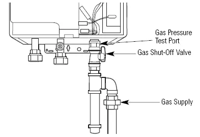
WATER PIPING
GENERAL INSTRUCTIONS
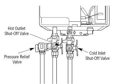
- The water supply should be shut off while connecting the water heater. Make sure the water inlet and outlet lines to the water heater fit in the diagram shown on page 7. A manual water control valve must be placed in the water inlet connection to the water heater before it is connected to the water line. Unions can be used on both the hot and cold water lines for future servicing and disconnection of the unit.
- The piping (including soldering materials) and components connected to this appliance must be approved for use in potable water systems.
- Purge the water line to remove all debris and air. Debris will damage the water heater.
- Toxic chemicals such as those used for boiler water treatment are not to be introduced to the potable water used for space heating.
- If the appliance will be used as a potable water source, it must not be connected to a system that was previously used with a nonpotable water heating appliance.
- Ensure that the water filter on the water heater is clean and installed. See the Cleaning the inlet filter section on page 19.
- New plumbing typically has contamination in the lines. The inlet water filter should be cleaned immediately after initial use.
CAUTION: Hot Water outlet pipes leaving unit can be hot to touch. Insulation must be used
for hot water pipes below 36″ due to burning risk to children.
PRESSURE RELIEF VALVE - Make sure the pressure relief valve is installed so there is clearance if the optional pipe cover (AGTPCM) is installed.
- An approved pressure relief valve is required by the American National Standard (ANSI Z21.10.3)/Canadian Standard (CSA 4.3)
for all water heating systems. - The relief valve must comply with the standard for Relief Valves and Automatic Gas Shutoff Devices for Hot Water Supply Systems (ANSI Z21.22) and/or the standard Temperature, Pressure, Temperature, and Pressure Relief Valves and Vacuum Relief Valves, CAN1-4.4.
- The relief valve must be rated up to 150 psi and to at least the maximum BTU/hr of the appliance.
- The discharge from the pressure relief valve should be piped to the ground or into a drain system to prevent exposure or possible burn hazards to humans or other plant or animal life. Follow local codes. Water discharged from the relief valve could cause severe burns instantly, scalds or death.
- The pressure relief valve must be manually operated once a year to check for correct operation.
- The relief valve should be added to the hot water outlet line according to the manufacturer’s instructions. DO NOT place any other type of valve or shut-off device between the relief valve and the water heater.
- Do not plug the relief valve and do not install any reducing fittings or other restrictions in the relief line. The relief line should allow for complete drainage of the valve and the line.
- If a relief valve discharges periodically, this may be due to thermal expansion in a closed water supply system. Contact the water supplier or local plumbing inspector on how to correct this situation. Do not plug the relief valve.
- Neither GE nor the American National Standard (ANSI Z21.10.3)/Canadian Standard (CSA 4.3) requires a combination temperature and pressure relief valve for this appliance; however, local codes may require a combination temperature and pressure relief valve.
INTERNAL BUILT-IN FREEZE PROTECTION - The freeze protection features include
electrical heating elements and intermittent firing of the burner. Freeze protection may be disabled if electricity or gas is not supplied, or if there is an error preventing the water heater from functioning.
NOTE: See Supplemental Freeze Protection on page 13.
CONNECTING THE WATER HEATER TO THE WATER SUPPLY
Water connections to the tankless water heater should follow all state and local plumbing codes.
If this is a standard installation, refer to the diagram on the following page under RECOMMENDED PIPING FOR BASIC INSTALLATION. If freeze protection valves are being installed, refer to the diagram under FREEZE PROTECTION FOR EXTERNAL PIPING on page 15.
- Plumb water supply to the tankless water heater on the 3/4″ MNPT connection at the bottom of the unit marked WATER INLET.
- Plumb the home hot water supply to the 3/4″MNPT connection marked WATER OUTLET
at the bottom of the unit.
NOTE: Make sure water lines to the water heater fit in the diagram shown on page 7. This is essential if a pipe cover accessory (model number AGTPCM) is to be installed.
SUPPLEMENTAL FREEZE PROTECTION
If the unit is installed in an environment that can freeze, follow state and local codes and apply heat trace to ALL water pipe and fittings located outside (attic, crawl space or building structure).
It is highly recommended in areas where freezing temperatures occur to install automatic drain valves that work in the event of a power loss. Refer to the diagram in the FREEZE PROTECTION FOR EXTERNAL PIPING section (page 15). These valves should be wired to a supply current.
In the event of a power loss, the system will
drain automatically. Be sure to test this system after installation by turning off power to ensure the system drains properly.
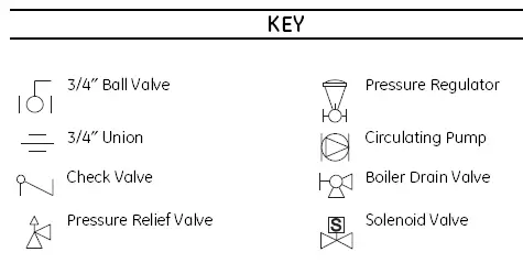
RECOMMENDED PIPING FOR BASIC INSTALLATION

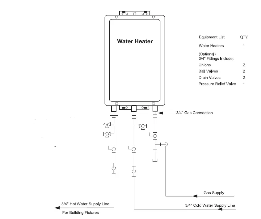
This is not an engineered drawing; it is intended only as a guide and not as a replacement for professionally engineered project drawings. This drawing is not intended to describe a complete system; it is up to the contractor/engineer to determine the necessary components for and configuration of the particular system being installed. The drawing does not imply compliance with local building code requirements; it is the engineer‘s/contractor’s responsibility to ensure the installation is in accordance with all local building codes. Confer with local building officials before installation.
FREEZE PROTECTION FOR EXTERNAL PIPING
IMPORTANT!
With electrical power supplied to the water heater, it will not freeze in environments as cold as -30°F, when protected from direct wind exposure.
In the event of a power failure at temperatures below freezing, the water heater should be drained of all water to prevent freezing damage.
The unit may be drained manually, or through the installation of the optional solenoid valves as shown.
The unit may be drained manually; however, we highly recommend that drain-down solenoid valves be installed that will automatically drain the unit if power is lost.
When the electrical power to the water heater fails, the 3/4″ solenoid valve closes (stopping the flow of water into the heater) and the 1/4″solenoid valve opens (allowing the water heater and associated piping to drain). Ensure that you run the drain for the solenoids to the outside environment to prevent discharging water inside the building, which can cause water damage.
NOTE: If the unit is installed in an environment that can freeze, follow state and local codes and apply heat trace to ALL water pipes and fittings located outside (attic, crawl space or building structure).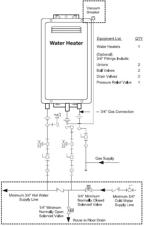
IMPORTANT!
With electrical power supplied to the water heater, it will not freeze in environments as
cold as -30°F, when protected from direct wind exposure.
In the event of a power failure at temperatures below freezing, the water heater should be drained of all water to prevent freezing damage.
The unit may be drained manually, or through the installation of the optional solenoid valves
as shown.
The unit may be drained manually; however, we highly recommend that drain-down solenoid valves be installed that will automatically drain the unit if power is lost.
When the electrical power to the water heater fails, the 3/4″ solenoid valve closes (stopping
the flow of water into the heater) and the 1/4″solenoid valve opens (allowing the water heater and associated piping to drain). Ensure that you run the drain for the solenoids to the outside environment to prevent discharging water inside the building, which can cause water damage.
NOTE: If the unit is installed in an environment that can freeze, follow state and local codes and apply heat trace to ALL water pipes and fittings located outside (attic, crawl space or building structure).
ELECTRICAL CONNECTION INFORMATION
WARNING – To reduce the risk of fire, electrical shock and personal injury:
The water heater must be electrically grounded in accordance with local codes and ordinances or, in the absence of local codes, in accordance with the NATIONAL ELECTRICAL CODE, ANSI/NFPA NO. 70, or the CANADIAN ELECTRICAL CODE, CSA C22.1.
ELECTRICAL REQUIREMENTS
This appliance must be supplied with 120V, 60Hz, and connected to a properly grounded branch circuit, protected by a 15- or 20-amp circuit breaker or time-delay fuse.
If the electrical supply provided does not meet the above specifications, it is recommended that a licensed electrician install an approved outlet.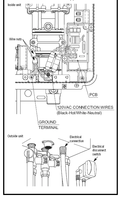
HIGH ALTITUDE INSTALLATIONS
Set dip switches 2 and 3 to the values shown in the table below for your altitude. The default setting for the appliance is 0-2000 ft (0-610 m) with switches No. 2 and No. 3 in the OFF position.
WARNING: Do not adjust the other dip switches unless specifically instructed to do so.
If unsure of the altitude in your location, call 1.888.HOTTER (888.467.9837).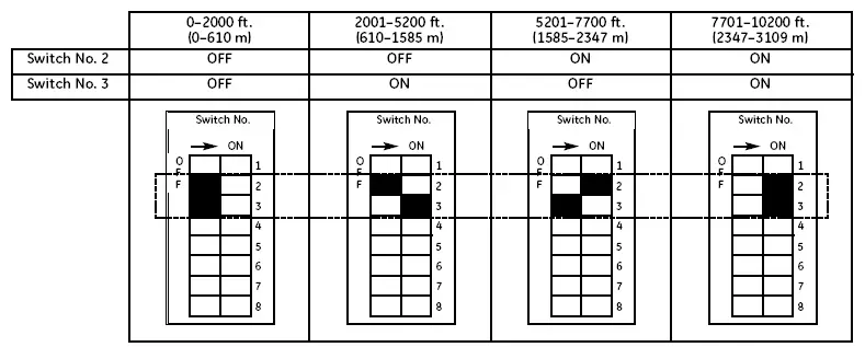
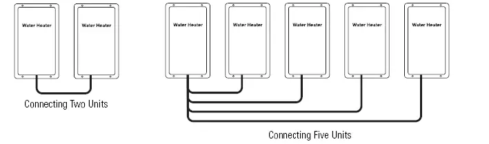
CASCADING MULTIPLE WATER HEATERS
The Dual Connect Cable Kit (AGTDC1) is an optional accessory that connects 2 water heaters and allows them to function as one hot water source.
The Multi Connect Kit (AGTCK1) and the Multi Connect Cable Kit (AGTMC1) are optional accessories that connect 3 to 5 water heaters and allow them to function as one hot water source.
Refer to the instructions that come with the accessory for complete installation information.
GUIDELINES
- Do not install the Dual Connect Cable Kit (AGTDC1) with the Multi Connect Kit (AGTCK1) and the Multi Connect Cable Kit (AGTMC1) because they are not designed to operate together.
- Water heaters should be installed less than
18 inches apart so that the cables will reach between units and to prevent temperature fluctuations (cold water sandwich effect) when the water is shut off and turned back on. - Temperature settings can only be changed on the controller for the primary unit.
| NUMBER OF CONNECTED WATER HEATERS | ACCESSORIES NECESSARY |
| 2 | (1) Dual Connect Cable Kit (AGTDC1) |
| 3 | (1) Multi Connect Kit (AGTCK1) and (1) Multi Connect Cable Kit (AGTMC1) |
| 4 | (1) Multi Connect Kit (AGTCK1) and (2) Multi Connect Cable Kits (AGTMC1) |
| 5 | (1) Multi Connect Kit (AGTCK1) and (3) Multi Connect Cable Kits (AGTMC1) |
REMOTE CONTROLLER INSTALLATION
LOCATION
- The controller should be out of reach of small children.
- Avoid locations where the controller may become hot (near the oven or radiant heater).
- Avoid locations in direct sunlight. The digital display may be difficult to read in direct sunlight.
- Avoid locations where the remote controller could be splashed with liquids.
- Do not install in locations where it can be adjusted by the public.
CONFIGURATIONS
A maximum of 4 remote controllers can be installed for a water heater or bank of water heaters. Controllers can only be wired in parallel. Controllers cannot be wired in series.
If 4 AGTRC are installed, press the Priority and On/Off buttons on the fourth controller until a beep sounds.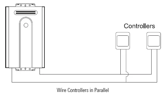
CABLE LENGTHS AND SIZE
The cable for the remote controller should be
a nonpolarized two-core cable with a minimum gauge of 22 AWG. The maximum cable length from each controller to the water heater depends on the total number of wired controllers connected to the water heater.
| NUMBER OF WIRED CONTROLLERS | MAXIMUM CABLE LENGTH FOR EACH CONTROLLER TO WATER HEATER |
| 1 | 328 ft. (100 m) |
| 2 | 164 ft. (50 m) |
| 3 or 4 | 65 ft. (20 m) |
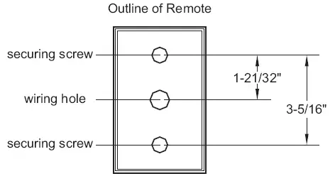
MOUNTING THE CONTROLLER
- Determine a suitable location for the controller.
- Mount a single gang outlet box in the wall where the remote control is indicated.
- Run the cable between the controller and the water heater or the controller and the other controller.
- Remove the face plate from the remote controller, using a screwdriver.
- Connect the cable to the remote controller.
- Mount the controller to the wall in the single gang outlet box installed in step 2.
- Disconnect the power from the water heater.
- Remove the cover of the water heater.
- Remove the plastic cover from the PCB and electrical connections.

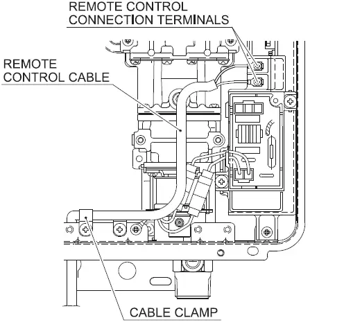
WARNING: DO NOT ATTEMPT
TO CONNECT THE REMOTE CONTROLLERS WITH THE POWER ON. - Thread the cable through the access hole at the base of the unit and connect the wires to the controller terminals on the bottom right-hand side of the PCB.
- Secure the controller cable using the clamp provided.
- Replace the plastic cover over the PCB, and then replace the cover of the water heater.

CLEANING THE INLET FILTER
It is imperative that control compartments, burners and circulating air passageways of the appliance be kept clean.
CAUTION:
Before performing this action, first remove power to the water heater and be sure not to stand near the discharge line of the pressure relief valve. This will prevent a possible scald injury.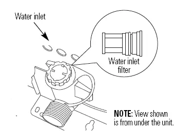
- Turn off and disconnect the electrical power. Allow the water heater to cool.
Shut off the water inlet. - Open the hot water tap at the nearest faucet.
- Close the outlet valve on unit.
- Have a small pan or bucket ready to catch spilled water.
- Remove and clean the water inlet filter with a small brush. If the scale is present, clean in a white vinegar solution.
- Replace the water inlet filter.
- Remove the front panel by removing 4 screws.
- Use pressurized air to remove dust from the main burner, heat exchanger and fan blades. Do not use a wet cloth or spray cleaners on the burner. Do not use volatile substances such as benzene and thinners. They may ignite or fade the paint.
- Use soft dry cloth to wipe the cabinet.
- Open water valves.
- Check for leaks.
- Connect the electrical power and turn on the unit.
INSTALLATION CHECKLIST
- Ensure 120 Volts A.C. is connected to the unit and that the circuit is turned on.
- Verify the gas system is functioning correctly by connecting your manometer to the gas pressure test port on the unit (see page 11). Operate all gas appliances in the facility. The inlet gas pressure on the unit MUST NOT DROP BELOW as listed on the unit rating plate for the gas type being used. A manometer can be used to check the pressure.
- Make sure you have cleaned the COLD water inlet filter screen.
- Inspect HOT (outlet) and COLD (inlet) water lines to ensure they have not been crossed and are leak-free.
- Ensure the manual gas valve packaged with the water heater is installed in the gas supply line (see page 10). Ensure the controller is installed and
- functioning. Instruct the consumer on how to operate the controller. Instructions are always supplied in the Owner’s Manual (see page 18). A typical water temperature set point is 120 degrees.
- For instructions on operating the unit, refer to the Owner’s Manual.
TECHNICAL DATA