![]()
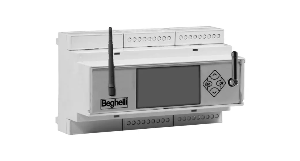
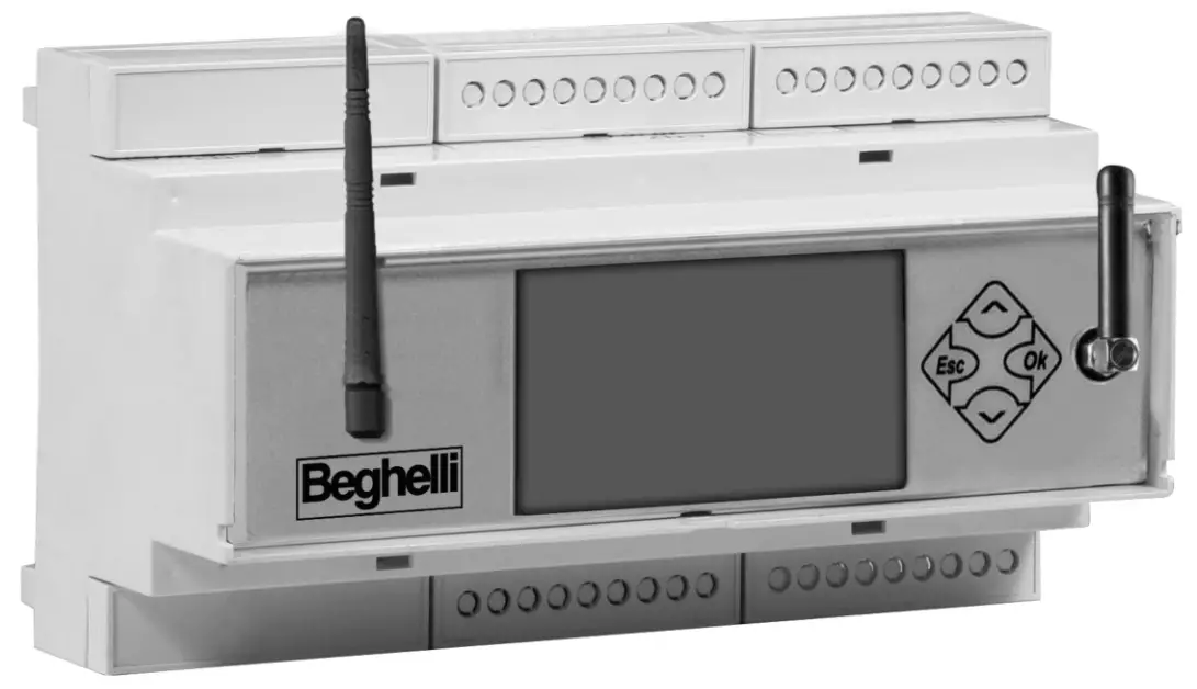
LOGICA FM CONTROL UNIT BY BEGHELLI
code 21102
Control Unit for the centralized control of normal and emergency lighting systems
 INSTALLATION
AND OPERATING INSTRUCTIONS
WHAT IS THE LOGICA FM CONTROL UNIT BY BEGHELLI
The Logica FM Control Unit by Beghelli (code 21102) is a device designed for the centralized control of normal and emergency lighting systems: it controls and supervises up to 992 Logica FM series luminaires via radio. The Logica FM Control Unit by Beghelli consists of:
- Keyboard + display for user operations;
- Radio interface on the 2.4GHZ-2.4835GHz band, (code 12130) DSSS “Spread Spectrum” modulation for connection to Logica FM series luminaires;
- RS485 interface for direct connection to a PC.
- RS232 interface for connection to the Logica DIN RS232 serial printer by Beghelli (code 3284).
- USB interface for software updates, backup, and restoring configuration data. – Integrated 4G LTE modem for remote connections via the Internet.
- Ethernet interface for LAN networks.
- Wi-Fi interface for PC connection.
To control the system from a remote PC, you need to get the Logica Visual software (code 12139) or the SD Manager software (code 20109).
FUNCTIONS
The Logica FM Control Unit performs the following tasks:
SYSTEM MONITORING
The Logica FM Control Unit continuously monitors the luminaires connected to it and it detects and signals any malfunctions.
SYSTEM CONTROL
The Logica FM Control Unit allows you to adjust the brightness of luminaires, perform Functional and Autonomy Tests on emergency luminaires in the system, schedule tests (date, time, and time intervals), etc.
KEEPING A LOGBOOK
The Logica FM Control Unit tracks test outcomes and, in general, any relevant operation in the system. If a printer is available (code 3284), this information can be regularly printed on paper. If a PC connection is available, this information can be sent and saved on a computer.
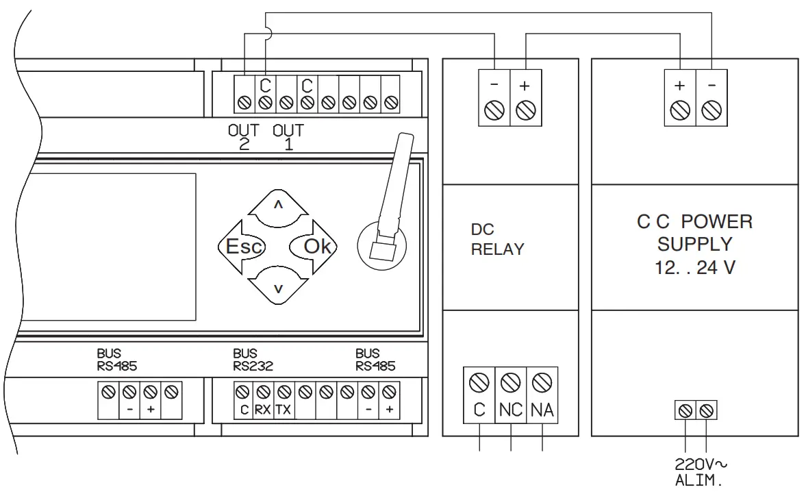
INSTALLATION
Use the layout below for reference to connect the Logica FM Control Unit to the Logica FM radio circuit and to the optional DIN printer (RS232 bus).
The connection with the system, using the Logica Visual or the SD Manager software, can be established through different channels:
– RS485-A;
– Ethernet;
– Modem 4G LTE integrato;
– Wifi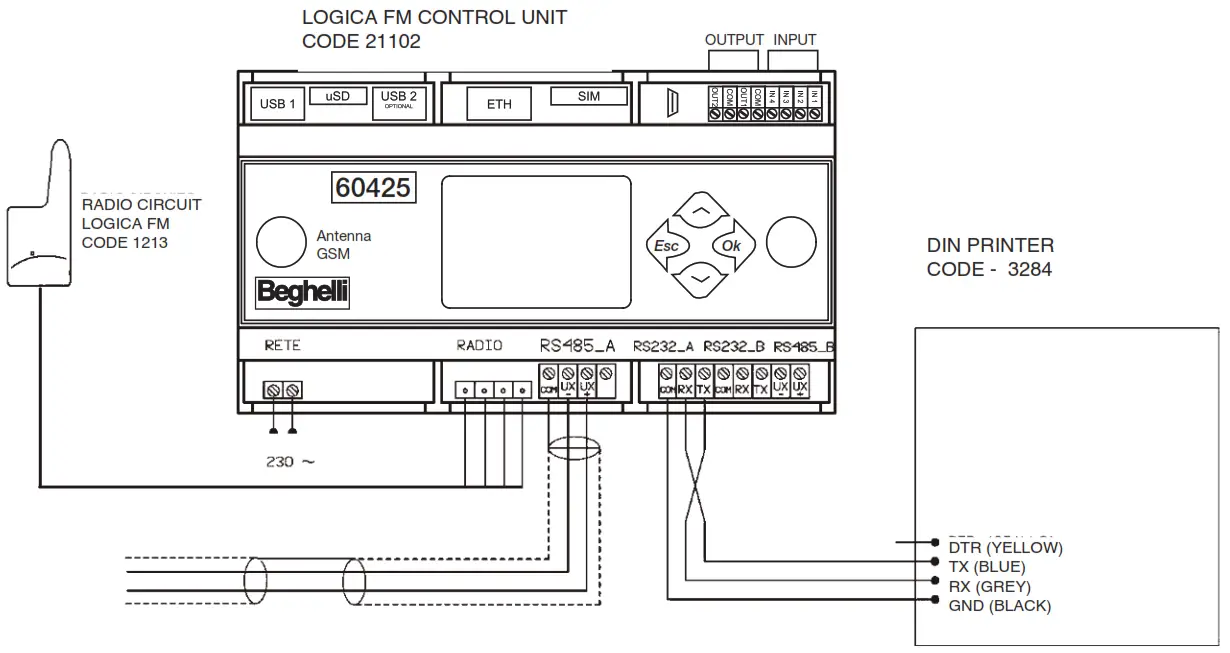
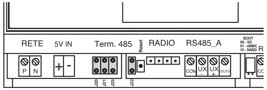
USE AND TERMINATION OF RS 485 LINES
The control unit is equipped with 2 independent RS 485 lines (RS485_A and RS485_B) both with an adaptation of the line impedance by inserting 2 riders at 2.54 pitch.
Line adaptation is necessary when the control unit is located as a “terminal” element of BUS 485 (start or end of the route).
To adapt the RS485_A line, insert the Jumper in connectors J22 and J23
To adapt the RS485_B line, insert the Jumper in connectors J20 and J21
OPERATIONS REQUIRED TO MAKE THE LOGICA FM CONTROL UNIT OPERATIONAL
KEYBOARD AND DISPLAY FUNCTIONS
Keys allow you to navigate through pages on the screen to view information and select operating modes.
The three main menus are LUMINAIRES, MAINTENANCE, AND STATUS;
– to move from one menu to another, use the “DOWN” ![]() and “UP”
and “UP” ![]() keys
keys
– to enter the menu and go deeper, use the “OK”![]() key
key
– to return to a higher menu level, use the “ESC”![]() key
key
Other functions of the keys are listed below:
Use the “DOWN” ![]() and “UP”
and “UP” ![]() keys to change a value (for example, in the Date and Time Settings menu, with the hour indication “08” flashing, press
keys to change a value (for example, in the Date and Time Settings menu, with the hour indication “08” flashing, press ![]() to increase the value to “09”, press
to increase the value to “09”, press![]() to decrease the value to “07”) and press the “OK”
to decrease the value to “07”) and press the “OK” ![]() key to confirm the entered value (by reference to the example given at the previous point: if, after changing the hour’s value to “07”, you press the
key to confirm the entered value (by reference to the example given at the previous point: if, after changing the hour’s value to “07”, you press the ![]() key, the value will be stored on the Control Unit).
key, the value will be stored on the Control Unit).
Note: If the panel is brand-new or if its memory has been reset (the Control Unit has no luminaires stored), some menus will not be visible.
TIME AND DATE SETTINGS
| At the first start-up, the system displays the LUMINA- RES menu: | | |
| Press | ||
 | ||
 | ||
| Press B to enter the menu that shows the date currently set on the Control Unit and the day indication will be flashing. Press To change it, follow the same procedure as for setting the day. | 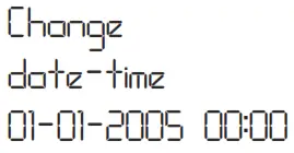 | |
| Apply the same method to set the year, hour and minutes. Press |  |
SEARCHING FOR FM LOGICA LUMINAIRES (NODE SEARCHING)
Note: Install the Control Unit and activate the wizard for luminaire searching before starting to install the luminaires. By doing so, whenever a luminaire is powered on, the Logica FM Control Unit will detect it and will display a prompt. At the end of the installation, the counter on the Control Unit display should report the exact number of installed luminaires (if not, check for turned off or faulty luminaires).
| Assuming you start from the LUMINAIRES menu: press the keys shown on the right in sequence to go to the luminaire searching menu (NODE SEARCHING). | ||
| | ||
 | ||
 | ||
 | ||
| Press |  | |
| As soon as the Control Unit acquires the first luminaire, the display will show “NORMAL SEARCH”, which will then be replaced by the following indications:- 008(008): number of luminaires found (total number of luminaires stored in the Control Unit) | 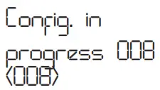 | |
| When the total number of luminaires stored on the Control Unit reaches the number of luminaires installed in the system, press, | 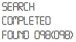 |
SCHEDULING FUNCTIONAL AND AUTONOMY TESTS
Functional and Autonomy Tests check the emergency luminaires. A Functional Test consists in turning on a luminaire for about 30 seconds during which time the luminaire light source and battery efficiency are checked; an Autonomy Test consists in turning on a luminaire over a longer time at the end of which the battery efficiency is checked. If a test reveals a luminaire is faulty, this information will be transferred from the luminaire to the Logica FM Control Unit: an error message will be displayed on the screen and the error will be recorded in the Logbook.
For a correct operation of the system, the following must be set:
– Date and time of the next Functional Test;
– Date and time of the next Autonomy Test;
– The time interval between repeated Functional Tests;
– The time interval between repeated Autonomy Tests.
Example of how to set the date and time for the next Functional Test:
| Assuming you start from the LUMINAIRES menu: press the keys shown on the right in sequence to go to the date&time settings menu for the next Functional Test. (“x 2” means you have to press the key twice) | ||
 | ||
 | ||
 | ||
| Now press To set the time of the test, proceed as shown in the section “Date and Time Settings”. | 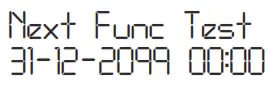 |
GROUPS
Luminaires connected to each Logica Control Unit by Beghelli can be divided into groups to perform separate operations on system sections. Each luminaire can belong to a group, multiple groups, or no group. The total number of groups available is 16.
ASSIGNING A LUMINAIRE TO A GROUP
| Assuming you start from the LUMINAIRES menu: press the keys shown on the right in sequence to go to the menu to set the group of the first luminaire on the list (“x 4” means you have to press the key four times) |
| |
| C | ||
| B |  | |
| C x4 |  | |
| B |  | |
| C | 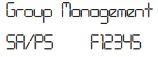 | |
| Press – 0: the luminaire does not belong to the group – 1: the luminaire belongs to the group Before the first configuration, the row has sixteen ‘0’,i.e. the luminaire F12345 does not belong to any group; the cursor will flash on the last zero to the left that corresponds to group 1.Press: –  B to move to the next group B to move to the next group– A to move to the previous group – To include the luminaire in the group – To exclude the luminaire from the group | 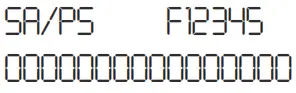 |
MENU
The system is organized in menus that allow you to access varied features of the system: turn luminaires on and off, perform Functional and Autonomy Tests, review information on malfunctions, etc.
To understand how to navigate among screens using the keys, see section “Keyboard and Display Functions”.
Most operations available can be applied to the entire system or to parts of it, as shown in the following table:
| For: | go to (menu): |
| all luminaires in the system | ALL |
| a single luminaire (e.g. luminaire LOGICA SA code F01234) | SA/PS F01234 |
| all luminaires in Group yy | GROUP 03 |
There are 3 menus: LUMINAIRES, MAINTENANCE AND STATUS.
LUMINAIRES MENU
Use this menu to adjust the brightness of the luminaires:
| go to (menu): | |
| for a maximum brightness level | ON (MAX) |
| to turn them off | TO TURN THEM OFF |
| for an intermediate brightness level (e.g. level 5) | DIMMER STEP 05 |
MANUAL TEST
Functional and Autonomy Tests check the emergency luminaires. A Functional Test consists in turning on a luminaire for about 30 seconds during which time the luminaire use and battery efficiency are checked; an Autonomy Test consists in turning on a luminaire over a longer time at the end of which the battery efficiency is checked.
Normally, Functional and Autonomy Tests are run automatically at regular intervals according to the schedule set by the user (see Scheduling Functional and Autonomy Tests”), but it is also possible to perform a Functional Test or an Autonomy Test directly from the keyboard: Manual Test. Manual Tests stop at the end of the set time or by sending a stop test command.
Manual Tests will not change the time intervals and durations set for automatic tests.
Use the MANUAL TEST menu to perform operations described in the following table:
| To: | go to (menu): |
| run a Functional Test | FUNCTION |
| run an unlimited time test that will stop when the battery is completely discharged | ON INDEFINITELY |
| an Autonomy Test of 1 hour | 1 h AUTONOMY TEST |
| stop any test | STOP TEST |
EMERGENCY
Note: Commands in the EMERGENCY menu will only affect luminaires that are not powered from the mains, i.e. they are lit in a state of emergency. When power from the mains to a luminaire is cut off, the luminaire will turn on and run on the battery supply. As long as its battery still has energy stored, a luminaire can be sent the following commands:
– Disable the state of emergency: the luminaire turns off; it can be turned back on by enabling the state of emergency.
– Enable the state of emergency: the luminaire turns on
– Turn off: the luminaire is turned off permanently; it cannot be turned back on unless the luminaire itself detects power being fed from the mains. This feature can be useful to preserve battery power when, for instance, the power supply to the system needs to be cut off for a long period.
| To: | go to (menu): |
| disable the state of emergency | EM. OFF |
| enable the state of emergency | EM. ON |
| permanently turn off the luminaire | TO TURN THEM OFF |
MANAGEMENT TEST
This menu allows you to set:
– Date and time of the next Functional Test;
– Date and time of the next Autonomy Test;
– The time interval between repeated Functional Tests;
– The time interval between repeated Autonomy Tests.
For further details on how to set test dates, times, and time intervals, see section “Scheduling Functional and Autonomy Tests”.
Based on their unique identifying addresses, LOGICA luminaires are divided into EVEN-numbered and ODD-numbered luminaires. Using the EVEN-ODD TEST menu, you can decide whether to perform an autonomy test on all luminaires simultaneously or first on the odd-numbered luminaires, then, 7 days later, on the even-numbered luminaires.
| To: | go to (menu): |
| set a single simultaneous test for all luminaires | SIMULTANEOUS |
| set a test for even-numbered luminaires 7 days after the test on odd-numbered luminaires | DELAY 7 DAYS |
CONTROL UNIT MANAGEMENT
Date & Time Changes
To set the date and time on the Logica FM Control Unit,, see section “Date and Time Settings”.
Printing
Note: Printing will be available if the Logica FM Control Unit is connected to a Logica DIN RS232 serial printer by Beghelli (code 3284).
The following data can be printed:
– Configuration: List of installed luminaires and their characteristics (model, even/odd-numbered, 1hr/3hrs autonomy, etc.).
– Scheduling: Timetables for Functional and Autonomy Tests, time intervals for testing, staggered testing on odd- and even-numbered luminaires.
– Errors: For each faulty luminaire, a warning is given that specifies the type of fault (e.g. 8W neon tube error, battery charging error, etc.).
– Reports: For this menu, you must enter a start date and an end date for the report. The printout will list significant actions that occurred over the set time frame involving the Logica Control Units by Beghelli installed in the system. The printout will report the start time and the end time of Functional or Autonomy Tests performed, be they manual or automatic tests, and a list of faulty luminaires.
The following controls are available in the PRINT menu:
| To: | go to (menu): |
| print the Configuration | CONFIGURATION |
| print the Scheduling | SCHEDULING |
| print Errors | ERRORS |
| print Reports | REPORT |
Language
The user can set a different display language. Available languages: ITALIAN, GERMAN, and ENGLISH.
Outputs OUT1 – OUT2 – OUT3 on/off
The user can enable or disable one or more outputs to signal errors in the system.
Outputs OUT1 – OUT2 – OUT3 Active Open/Closed
Once enabled, outputs can be set in N/C or N/A mode; “N/C” means the output will open if an error occurs; “N/A” means the output will close if an error occurs.
CONFIGURATION
This menu is usually used when installing the lighting system when replacing or adding luminaires when replacing the Logica FM Control Unit.
| To: | go to (menu): |
| Search for luminaires in the system | FIND NODES CONT. |
| delete all luminaires stored on the Control Unit | DELETE NODES |
| delete the communication network for tree-structured luminaires | DELETE RADIO NETWORK |
| create a radio network between the Control Unit and all luminaires in the system | CREATE RADIO NETWORK |
At the first installation (see section “Searching for Logica FM Luminaires (Node searching)”) and whenever luminaires are added to the system, run “FIND NODES CONT.”.
If one or more luminaires are replaced or deleted from the system, run “DELETE NODES” and then “FIND NODES CONT.”.
If there are communication troubles with some luminaires in the system, run “DELETE RADIO NETWORK” and then “CREATE RADIO NETWORK”.
STATUS MENU
This menu allows the user to access additional information about the CONTROL UNIT and LOGICA FM LUMINAIRES.
CONTROL UNIT
This menu allows the user to access additional information about the CONTROL UNIT and LOGICA FM LUMINAIRES.
LOGICA FM LUMINAIRES
Access this menu to display the software version of the Control Unit, the total number of nodes, and the number of luminaires with errors.
TECHNICAL FEATURES
Code – 21102
– Battery: 2 x NiCd 3.6V – 750mAh
– Power supply voltage: 230V
– Max. input power: 12VA
– Operating ambient air temperature: -10°C – 55°C
Features of the Radio Transmitter
– Frequency band: 2.4GHZ-2.4835GHz
– RF Power: <100mW e.i.r.
WARNINGS – WARRANTY
– Before connecting the device, make sure the data on the rating plate match the specifications of the mains.
– This device must be used according to its intended use. Any other use shall be deemed improper and, therefore, dangerous. The manufacturer shall not be held liable for any injury or damage caused to persons, animals, or property as a result of improper, incorrect, or unreasonable use.
– Before any cleaning or maintenance operations, disconnect the device from the mains.
– Warning: This product contains materials that may be harmful if disposed of in the environment.
– The device must not be disposed of as municipal waste. It must be subjected to separate collection to avoid environmental pollution. In compliance with Directive 2002/96 and implementing national laws on end-of-life product disposal, a failure to comply with the above is sanctioned by law.![]()
– For any repairs, contact an authorized technical service center and ask them to use the original spare parts. A failure to comply with the above may compromise the safety of the device.
– For details on interventions under warranty, please contact us at 800 626626 (toll-free) or contact your Authorized Reseller.
Beghelli S.p.A. declares that the radio transceiver complies with the 2014/53/EU European Directive.
The full text of the EU Declaration of Conformity for the device is available on the website, at www.beghelli.it/en/technical-area/tools/download.
The device may be used under the ‘free use policy.
 |  |
www.beghelli.com
BEGHELLI S.p.A. – Via Mozzeghine 13/15 – Monteveglio 40053 Valsamoggia (BO) – ITALY Phone
+39 051 9660411 – Fax +39 051 9660444 – Toll-free no. 800 626626


