DELTA RS-232 Rack Mount UPS Series
Product Introduction
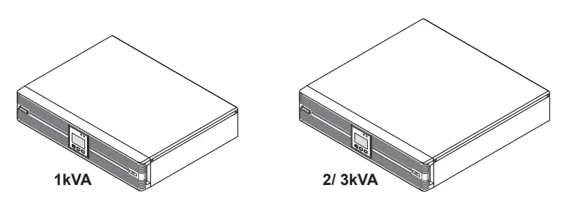
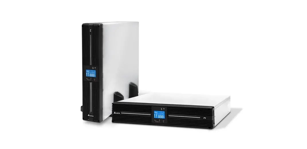
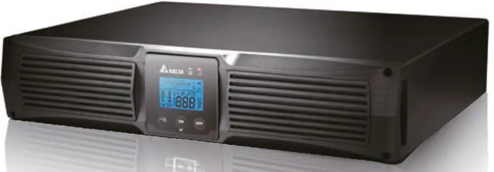
The R series UPS, available in 1kVA, 2kVA and 3kVA, is a single-phase on-line Uninterruptable Power Supply (UPS) system, which outputs reliable sine-wave power to your electrical equipment. The product is designed with advanced technology and high quality components. Its output power factor is up to 0.9 and efficiency in on-line mode reaches 93% (for 2kVA/ 3kVA). The unit not only protects your electrical equipment by providing secure and reliable uninterruptable power supply but also produces greater electric power efficiency at less cost.
The Amplon Family R series UPS is a light, compact and easy to use solution for IT applications and features rated nominal power capacities of 1kVA, 2kVA and 3 kVA. Each kVA model has no internal battery but can be connected to at least one external battery pack (user-supplied).
Safety Instructions
- Placement and Installation
- Read the Quick Guide carefully to ensure correct and safe usage of the product.
- Install the UPS in a well-ventilated area, away from rain, excess moisture, dust, flammable gas or explosives.
- To reduce the risk of fire or electric shock, install the UPS in a temperature and humidity controlled indoor area free of conductive contaminants. Please refer to 10 Technical Specifications for operating temperature and relative humidity.
- Leave adequate space at least 15cm around each side of the UPS for proper ventilation.
- Connection warnings
- Make sure the UPS is well grounded to avoid a possible risk of current leakage.
- The installation of protective devices (a DC non-fuse breaker or a DC fuse) is highly recommended when the UPS is connected to the power source and critical loads.
- The protective devices connecting to the UPS must be installed near the UPS and must be easily accessible for operation.
- Do not use extension cord to connect the UPS to an AC outlet.
- Do not plug the UPS input power cord into its own output receptacles.
- Prior to moving or reconnecting the UPS, disconnect the AC input power and ensure the UPS is powered off; otherwise, hazardous voltage may still exist at the output receptacles of the UPS, which presents a possible risk of current leakage.
- If you don’t use the output power cord came with the UPS, please ensure the length of the output power cord is shorter than 10m.
- Usage warnings
- The UPS is an EMC Class A product, which may cause wireless interference in your living environment. Precautions need to be taken to prevent possible interference.
- The UPS can be used to power computers and associated peripheral devices, such as monitors, modems, cartridge tape drives, external hard drives, etc.
- It is not recommended to connect the UPS with the following types of loads. For the load suitability, please contact Delta customer service before purchasing.
- regenerative loads (e.g. CNC machines and lifts)
- asymmetrical loads (e.g. fans with half-bridge drivers and laser printers)
- The external slits and openings in the UPS are provided for ventilation. To ensure reliable operation of the UPS and to protect the UPS from overheating, these slits and openings must not be blocked or covered.
- Before usage, you must allow the UPS to adjust to room temperature (20°C~25°C) for at least one hour.
- Do not splash any liquid on the UPS and be sure to prevent any foreign material from dropping into the UPS. Do not put beverages on or nearby the UPS.
- In an emergency, hold and press the OFF button, and release the button after you hear one beep to turn off the UPS. Meanwhile, cut off the mains to shut down the UPS.
- Never use cleaning liquid or spray to clean the UPS. Before cleaning, make sure you have (1) completely shut down the UPS, (2) unplugged the UPS from the power outlet, and (3) disconnected the unit from the external battery pack(s).
- Only qualified personnel can perform maintenance service. Do not open or remove the covers or panels of the UPS to avoid high voltage electric shock.
- You must contact Delta customer service if either of the following events occur:
- Liquid is poured or splashed on the UPS.
- The UPS does not run normally after carefully following the instructions in this Quick Guide.
- Battery Precautions
- Do not dispose of the battery or batteries in a fire. The batteries may explode. Do not open or damage the battery or batteries. The released electrolyte is harmful to the skin and eyes and may be toxic.
- Servicing batteries and battery packs should be performed or supervised by qualified service personnel who are knowledgeable in batteries, battery packs and the required precautions.
- The risk of dangerous voltage is possible when the batteries are still connected to the UPS even though the UPS is disconnected from the mains. Do not forget to disconnect the battery cable to completely cut off the battery source.
- Only use the same type of batteries from the same supplier. Never use old, new and different Ah batteries at the same time.
- A battery can present a risk of electrical shock and high short circuit current. The following precautions should be observed when working on batteries:
- Remove watches, rings or other metal objects.
- Use tools with insulated handles.
- Wear rubber gloves and boots.
- Do not lay tools or metal parts on top of batteries.
- Disconnect the charging source prior to connecting or disconnecting battery terminals.
- Do not reverse or short circuit the polarity + and – when connecting the batteries because this will destroy the device and constitute a risk of electric shock or fire.
WARNING:
- Even though the UPS is disconnected from the mains, a battery may still present electrical shock and short circuit current hazard. Ensure to cut off the battery source prior to the UPS maintenance.
- When the external battery pack(s) is(are) connected to the UPS, the installation of the protective devices (a DC non-fuse breaker or a DC fuse) is required to protect the unit.
Standard Compliance
- CE
- IEC/ EN 62040-1
- IEC/ EN 62040-2 Category C2
Packaging List
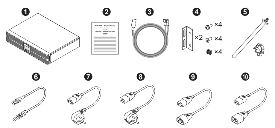
The UPS package contains the following items. Please check if any item is missing. If there is anything missing, please immediately contact the dealer.
- UPS102/ 202/ 302R2002N035

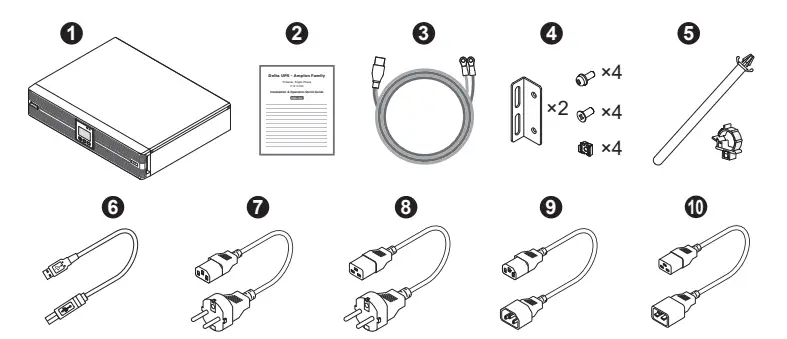
| No. | Item | Q’ty | 1K | 2/ 3K |
| 1 | UPS | 1 PC | ||
| 2 | Installation & Operation Quick Guide | 1 PC | ||
| 3 | Battery Wire | 1 PC | ||
| 4 | Bracket Ear | 1 SET | ||
| 5 | Battery Cable Tie | 1 SET | ||
| 6 | USB Cable | 1 PC | ||
| 7 | Input Power Cord 10A | 1 PC | ||
| 8 | Input Power Cord 16A | 1 PC | ||
| 9 | Output Power Cord 10A | 1 PC | ||
| 10 | Output Power Cord 16A | 1 PC |
- UPS102/ 202/ 302R2002N0B6
| No. | Item | Q’ty | 1K | 2/ 3K |
| 1 | UPS | 1 PC | ||
| 2 | Installation & Operation Quick Guide | 1 PC | ||
| 3 | Battery Wire | 1 PC | ||
| 4 | Bracket Ear | 1 SET | ||
| 5 | Battery Cable Tie | 1 SET | ||
| 6 | USB Cable | 1 PC | ||
| 7 | Input Power Cord 10A | 1 PC | ||
| 8 | Input Power Cord 16A | 1 PC | ||
| 9 | Output Power Cord 10A | 1 PC | ||
| 10 | Output Power Cord 16A | 1 PC |
- UPS102/ 202/ 302R2002N0B0

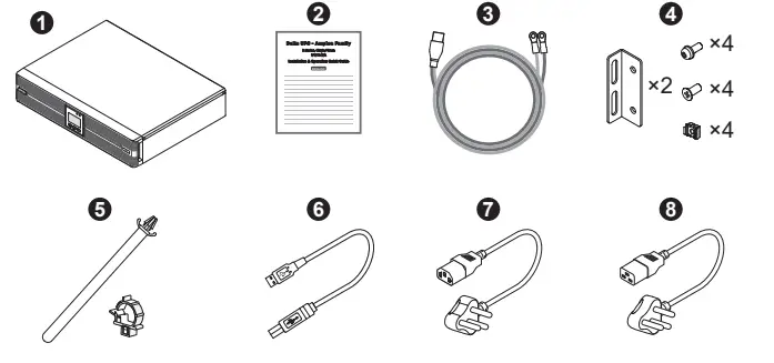
| No. | Item | Q’ty | 1K | 2/ 3K |
| 1 | UPS | 1 PC | ||
| 2 | Installation & Operation Quick Guide | 1 PC | ||
| 3 | Battery Wire | 1 PC | ||
| 4 | Bracket Ear | 1 SET | ||
| 5 | Battery Cable Tie | 1 SET | ||
| 6 | USB Cable | 1 PC | ||
| 7 | Input Power Cord 10A | 1 PC | ||
| 8 | Input Power Cord 16A | 1 PC |
Rear Panel
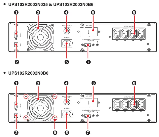
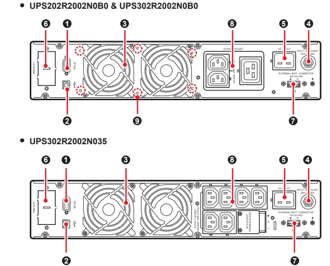
| No. | Item | Functions |
| 1 | RS-232 Port | For communicating with a PC to monitor the status of the UPS. UPSentry 2012 Software is required. Please download it from http://www.deltapowersolutions. com/en/mcis/software-center.php. NOTE: Do not use the USB port and the RS-232 port at the same time. If you connect the USB cable to the USB port, the RS-232 port will be disabled right away. |
| 2 | USB Port | |
| 3 | Fan(s) | For cooling and ventilation purpose. |
| 4 | Input Breaker | Prevents the UPS from damage caused by high current and protects the utility power from further damage when the UPS fails. |
| 5 | AC Input (Input Socket) | Connects the UPS to the mains. |
| 6 | Mini Slot | Connects to a Mini SNMP, Mini Relay I/O or Mini MODBUS card (optional) to manage the UPS. |
| 7 | External Batt. Connector | Connects to the external battery pack(s) to extend back up time (+, -, and terminals are included). 1 kVA : 24Vdc.40A 2 kVA : 48Vdc.40A 3 kVA : 72Vdc.40A |
| 8 | Output Socket & UPS Output Terminal Block | Connects the loads to the UPS. The UPS output terminal block is only applicable for UPS302R2002N035. |
| 9 | Anti-Insect Net Mounting holes | For mounting the anti-insect net (optional) to prevent insects from entering into the UPS. Only applicable for the UPS models ending with suffix B0 (UPS102R2002N0B0, UPS202R2002N0B0, and UPS302R2002N0B0). |
Operational Panel
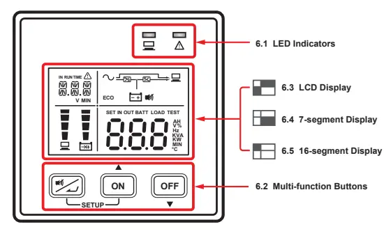
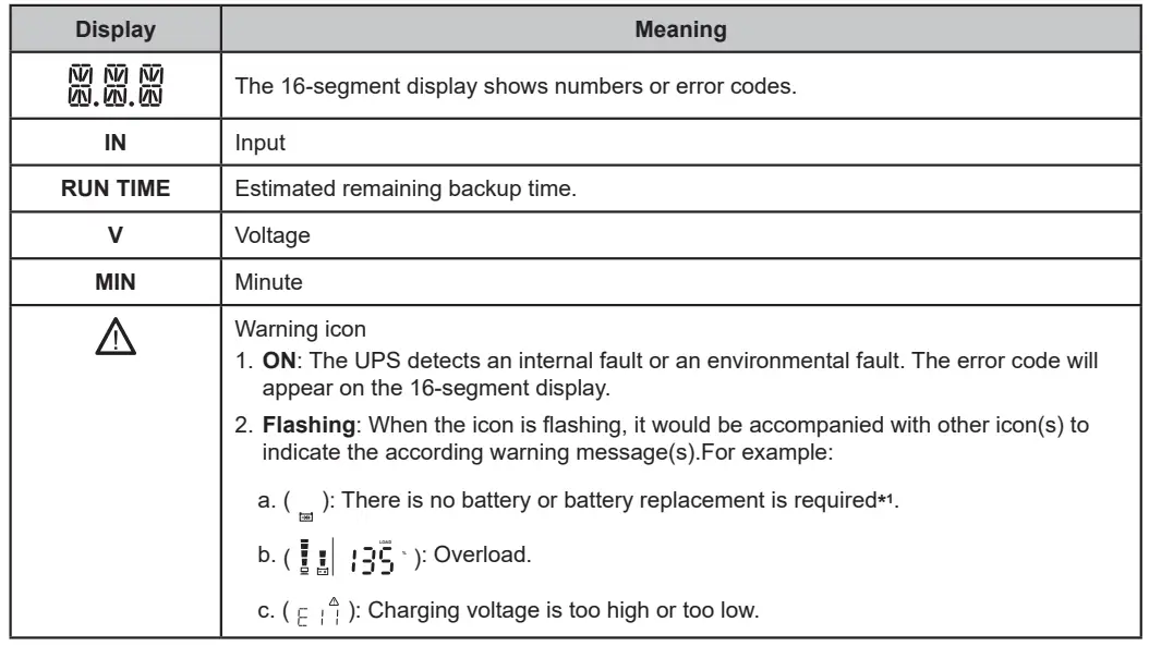
LED Indicators
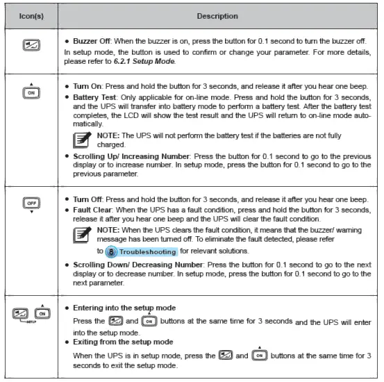
| Icon(s) | Description |
|
| Indicates the output status. ON (green): Output; OFF: No output. |
|
| 1. ON: The UPS detects an internal fault or an environmental fault. The error code will appear on the 16-segment display. 2. Flashing: When the icon is flashing, it would be accompanied with other icon(s) to indicate the according warning message(s). For example: a. ( ): There is no battery or battery replacement is required. LOAD b. ( % ): Overload. c. ( ): Charging voltage is too high or too low. |
NOTE:
- When the LCD display gets dim, press any of the above-mentioned buttons to wake up the LCD display and enable each button function.
- Only qualified service personnel can perform setup action.
- For more information about the setup mode, please refer to 6.2.1 Setup Mode.
Setup Mode
Please note that only qualified service personnel can perform setup action. In setup mode, you can set up the following items. For some settings, they can’t be set in certain operation modes. Please refer to the table below for relevant information.
| Setup Item | Standby mode | On-line mode | Bypass mode | Battery mode | ECO mode | Frequency converter mode | |
| The code shown on the 16-segment display | Meaning | ||||||
| INV *1 | Inverter Voltage Setup | V | X | V | X | X | X |
| INV *1 | Inverter Frequency Setup | V | X | V | X | X | X |
| COV | Frequency Converter Setup | V | X | V | X | X | X |
| STB | Standby Bypass Setup | V | V | V | V | V | V |
| ECO | ECO Setup | V | V | V | V | V | X |
| Setup Item | Standby mode | On-line mode | Bypass mode | Battery mode | ECO mode | Frequency converter mode | |
| The code shown on the 16-segment display | Meaning | ||||||
| ALM | Overload Alarm Setup | V | V | V | V | V | V |
| BUZ | Buzzer Setup | V | V | V | V | V | V |
| BYP | Bypass Range Setup | V | V | V | V | V | V |
| CAP | Battery Capacity Setup | V | V | V | V | V | V |
| STG | Battery String Setup | V | V | V | V | V | V |
| AST | Auto-Start To On- line Setup | V | X | V | X | X | X |
| PF | Power Factor Setup | V | X | V | X | X | X |
| RST | Restore Default Setup | V | X | V | X | X | X |
NOTE:
*1: Both of the ‘Inverter Voltage Setup’ and ‘Inverter Frequency Setup’ use the same code, but you can tell whether the UPS is in ‘Voltage’ or in ‘Frequency’ setup by checking the information shown on the 7-segment display.
The table below lists each setup item’s setting parameters.
| Setup Item | Setting Parameters*1 | |
| The code shown on the 16-segment display | Meaning | |
| INV | Inverter Voltage Setup | 200V, 208V, 220V (Default), 230V, 240V |
| INV | Inverter Frequency Setup | 50Hz (Default), 60Hz |
| COV | Frequency Converter Setup | OFF (Default), ON*2 |
| STB | Standby Bypass Setup | OFF, ON (Default)*3 |
| ECO | ECO Setup | OFF (Default), ON |
| ALM | Overload Alarm Setup | 60%, 70%, 80%, 85%, 90%, 95%, 100%, 105% (Default) |
| BUZ | Buzzer Setup | ENA (Enable) (Default), DIS (Disable) |
| BYP | Bypass Range Setup | 5%, 6%, 7%, 8%, 9%, 10%, 11%, 12%, 13%, 14%, 15% (Default), HI1, HI2, HI3*4 |
| CAP | Battery Capacity Setup | 0AH (Default), 5AH, 7AH, 9AH, 12AH, 15AH, 24AH, 33AH, 38AH, 40AH, 50AH, 65AH, 80AH, 100AH, 120AH, 150AH, 200AH*5 |
| STG | Battery String Setup | 0 (Default), 1, 2, 3, 4, 5, 6, 7, 8, 9*5 |
| Setup Item | Setting Parameters*1 | |
| The code shown on the 16-segment display | Meaning | |
| AST | Auto-Start To On-line Setup | OFF (Default), ON*6 |
| PF | Power Factor Setup | 70, 80, 90 (Default) |
| RST | Restore Default Setup | NA (Default), DEF*7 |
NOTE:
- *1: The setting parameters are described in text format; please refer to actual icons or codes shown on the LCD display when performing the setup action.
- *2: If the setting is set to ‘ON’, the UPS will automatically disable the bypass function.
- *3: If the setting is set to ‘OFF’, the UPS will run in standby mode whenever the utility AC power is connected to the UPS or whenever you press the OFF OFF button in on-line mode.
If the setting is set to ‘ON’, the UPS will run in bypass mode whenever the utility AC power is connected to the UPS or whenever you press the OFF OFF button in on-line mode.
In standby mode, the UPS has no output voltage; in bypass mode, the UPS has output voltage. In either standby mode or bypass mode, the batteries will be charged. - *4: The percentage here indicates the bypass tolerance range for the current ‘Inverter Voltage’ setting. For HI1, the tolerance range is -20% ~ +15%; for HI2, -25% ~ +15%; for HI3, 120Vac ~ 276Vac.
- *5: If the UPS is not connected to the external battery pack(s), you don’t need to adjust the setting.
Just keep the default setting as ‘0’. If the UPS is connected to the external battery pack(s), you have to set up ‘CAP’ and ‘STG’ these two items based on the battery capacity and the strings of the external battery pack(s). If the
parameters of the external battery pack(s) do not match the UPS’s built-in setting options, please choose the closest parameters for the battery setting. - *6: This setup item only affects the UPS’s operation mode whenever the utility AC power is connected to the UPS.
If the setting is set to ‘OFF’, the UPS will operate according to the ‘STB’ setting.
If the setting is set to ‘ON’, the UPS will start up and run in on-line mode automatically. - *7: When you select ‘DEF’, each of the parameters will be restored to the default value. If any setting deviates from the default value or is different from what you expect, you may adjust the setting.
- For setup procedures, please refer to the following:
- Simultaneously press the two buttons ON
SETUP for 3 seconds to enter the setup mode. - Press the ON button for 0.1 second or press the OFF button for 0.1 second to view the previous or the next display.
- Press the button for 0.1 second to enter the item that you want to set up.
- Press the ON button for 0.1 second or press the OFF button for 0.1 second to increase or decrease the parameter value.
- Press the button for 0.1 second to confirm your parameter setup.
- After that, press the ON button for 0.1 second or press the OFF button for 0.1 second to go to the previous or the next setup item.
- In setup mode, simultaneously press the two buttons ON
SETUP for 3 seconds, the LCD will exit from the setup mode. - In setup mode, if you don’t press any button for more than 2 minutes, the LCD will exit from the setup mode and go back to the original display automatically.
- Simultaneously press the two buttons ON
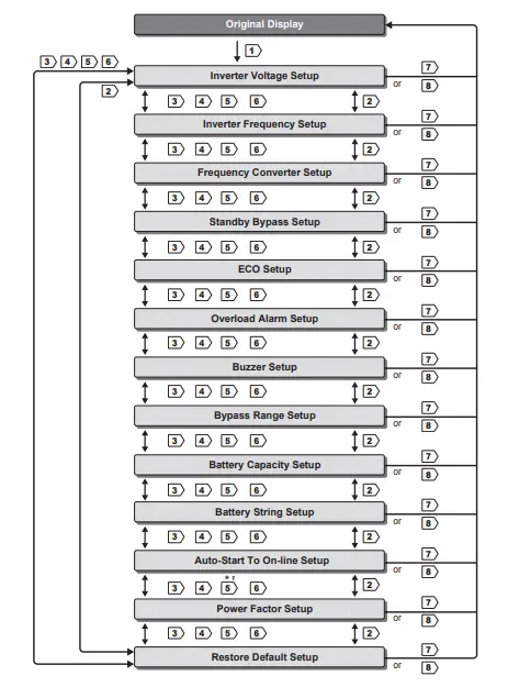
- Setup Mode Flow Chart
 NOTE:
NOTE:
*1: In standby mode or in bypass mode, if you change the ‘AST’ setting from ‘OFF’ to ‘ON’ and execute the step 5 to confirm such change, the UPS will exit from the setup mode and run in ‘Auto-Start to On-line’ mode right away.
 NOTE:
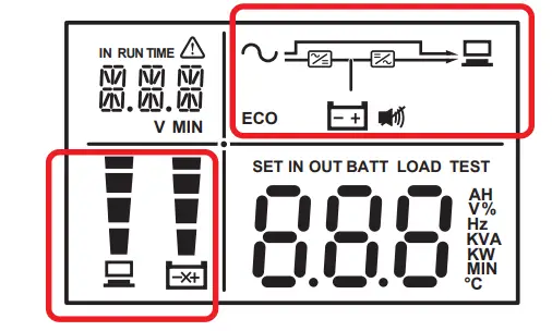
NOTE:LCD Display
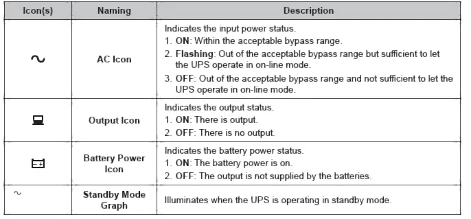
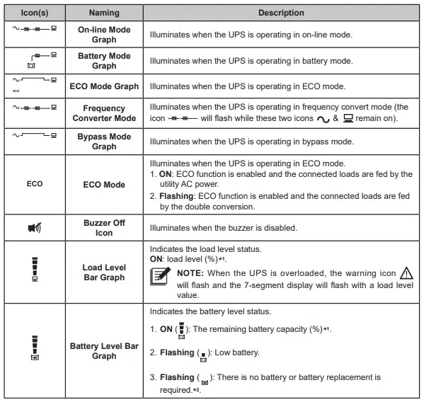
NOTE:
- *1: means that:
- 1%~25%: the 1st segment will illuminate.
- 26%~50%: the first two segments will illuminate.
- 51%~75%: the first three segments will illuminate.
- 76%~100%: all segments will illuminate.
- 2. *2: If you need to replace the external battery pack(s), please contact service personnel.
7-segment Display
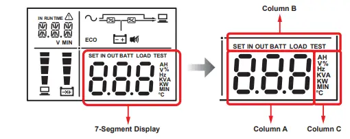
NOTE: Please read the columns A, B and C together to understand the LCD information, such as input voltage, estimated remaining backup time, etc.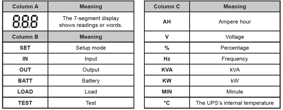
16-segment Display
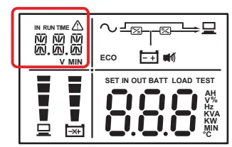
NOTE:
*1: If you need to replace the external battery pack(s), please contact service personnel.NOTE:
*1: If you need to replace the external battery pack(s), please contact service personnel.
Turn-on/ Turn-off Procedures
| Turn-on Procedures | Turn-off Procedures |
|
|
Troubleshooting
When you see the following problems occur, please follow the solutions shown below.
- About the error codes shown on the 16-segment Display:
Error Code Meaning Possible Cause Solution E11 Charger Warning Charging voltage is too high or too low. Please contact service personnel. E12 Fan Fault Fan(s) is(are) damaged or stuck. - Check if foreign matter is stuck in the fan(s). If yes, please remove it.
- Please contact service personnel.
E13 Temperature Out of Range
The UPS temperature is out of range.
- Check whether the UPS has adequate ventilation.
- Decrease the loads.
- Check whether the fan(s) run(s) normally.
- Clean the filters (if you have installed any).
E14 +/- DC BUS
High/ Low- There are inductive loads such as transformers connected to the UPS output.
- Abnormalities are detected in the UPS.
- Turn on the UPS after the loads have been connected to the UPS in bypass mode.
- Please contact service personnel.
Error Code Meaning Possible Cause Solution E16 Inverter Fault Abnormalities are detected in the UPS. Please contact service personnel. E18 DC-DC Fault Abnormalities are detected in the UPS. Please contact service personnel. E19 Abnormal Output/ Inverter Voltage Abnormalities are detected in the UPS. Please contact service personnel. E21 O/P Short A short-circuit issue has been detected in output. - Check whether the output has a short- circuit issue.
- Contact service personnel.
E77 Charger Fault Charger is damaged. Please contact service personnel. MBB MBB Shutdown The cover of the manual bypass box is removed. Please contact service personnel. OVL Overload Shutdown The UPS is overloaded. Decrease the connected loads. SD0 REPO Shutdown Emergent shutdown is executed. After emergent events are eliminated, follow the turn-on procedures to start up the UPS. SD1 RPO Shutdown Remote shutdown is executed from dry contact. After the remote shutdown events are eliminated, follow the turn-on procedures to start up the UPS. SD2 ‘Shutdown After’ Shutdown UPS delay shutdown is triggered. Please contact service personnel. SD3 ‘Battery Save’ Shutdown Shutdown is enabled after the UPS has run in battery mode for a specific time. Please contact service personnel. SD4 Battery Low Shutdown The UPS transfers into battery mode due to AC utility abnormality. However, the battery power is almost used up. - Check the main AC source and the status of the input power cord.
- Please contact service personnel.
SD5 ‘Cold Start Battery Empty’ Shutdown The batteries are damaged or battery lifetime is due. Please contact service personnel. - About other problems that might happen:
| No. | Problem | Possible Cause | Solution |
| 1 | Overload | The UPS is overloaded. | Decrease your connected loads. |
| 2 | Battery Missing | The battery cables are not connected or not firmly connected. |
|
| 3 | Weak Battery/ Battery Replacement | The batteries are damaged or battery lifetime is due. | Please contact service personnel. |
| 4 | Abnormal Input (when the AC icon is flashing) | The AC input voltage or frequency is out of the acceptable bypass range. |
|
NOTE: If all possible causes are eliminated but the alarm still appears, please contact your local dealer or customer service.
Optional Accessories
| No. | Item | Function |
| 1 | Mini SNMP Card | Monitors and controls the status of the UPS via a network system. |
| 2 | Mini Relay I/O Card | Increases the quantity of dry contacts. |
| 3 | Mini MODBUS Card | Lets the UPS have MODBUS communication function. |
| 4 | Cable & Wire Mount Assembly | Fastens an IEC output cable to prevent the cable from coming off. |
| 5 | Anti-Insect Net | Prevents insects from entering into the internal part of the UPS through the fan(s). |
| 6 | Charger Board (4A) | Increases the UPS charge current. |
| 7 | Maintenance Bypass Box | Continues supplying power to the connected loads when the UPS is under maintenance. |
| 8 | Tower Stands | Sustain the UPS vertically. |
| 9 | Rail Kit | Fixes the UPS in a rack cabinet firmly. |
NOTE:
- It is recommended to install the anti-insect net on the UPS models ending with suffix B0.
- For more details, please contact your local dealer or customer service.
Technical Specifications
| Model | R-1K | R-2K | R-3K | |
| Power Rating | 1kVA/0.9kW | 2kVA/1.8kW | 3kVA/2.7kW | |
| Waveform | Pure Sine Wave | |||
| Input | Nominal Voltage | 200*1 /208*1 /220/230/240 Vac | ||
| Voltage Range | 175 ~ 280 Vac (100% load); 80 ~ 175 Vac (50% ~ 100% load) | |||
| Input | Frequency | 50/60 Hz (± 10 Hz) | ||
| Power Factor | > 0.99 (full load) | |||
| iTHD | < 3% | |||
| Output | Power Factor | 0.9 | ||
| Voltage | 200*1 /208*1 /220/230/240 Vac | |||
| Voltage Regulation | ± 2% (linear load) | |||
| Frequency | 50/60 Hz (± 0.05 Hz) | |||
| vTHD | < 3% (linear load) | |||
| Overload Capability | < 105%: continuous; 105% ~ 125%: 1 minute; 125% ~ 150%: 30 seconds | |||
| Cress Factor | 3 : 1 | |||
| Connection | IEC C13 x 4 | Suffix 35/B6: IEC C13 x 6 |+ IEC C19 x 1 Suffix B0: IEC C13 x 2+ IEC C19 x 1 | Suffix 35: IEC C13 x 6+ Terminal Suffix B6: IEC C13 x 6+ IEC C19 x 1 Suffix B0: IEC C13 x 2+ IEC C19 x 1 | |
| Efficiency | On-line Mode | 91% | Up to 93% | |
| Battery | Battery Voltage | 24 Vdc | 48 Vdc | 72 Vdc |
| Battery | Backup Time | Depends on the capacity of the connected external battery pack(s) | ||
| Recharge Time | ||||
| Charge Current | 4A (can be increased to 8A via installation of 4A charge board (optional)) | |||
| Audible Noise*2 | < 40 dBA | < 43 dBA | < 43 dBA | |
| Display | LED indicators & LCD display | |||
| Communication Interfaces | MINI Slot x 1, RS-232 Port x 1, USB Port x 1 | |||
| Physical | Dimensions (W × D × H ) | 440 x 335 x 88 mm | 440 x 430 x 88 mm | 440 x 430 x 88 mm |
| Weight | 5.3 kg | 9 kg | 9.1 kg | |
| Environment | Operating Altitude | 1000 meters (without derating) | ||
| Operating Temperature | 0 ~ 50°C*3 | |||
| Relative Humidity | 5% ~ 95% (non-condensing) | |||
NOTE:
- *1: When the UPS is de-rated to 90% of its capacity.
- *2: If the UPS is running at < 75% load and in room temperature.
- *3: When the operating temperature is at 40~50°C, the UPS will be de-rated to 80% of its capacity.
- Please refer to the rating label for the safety rating.
- All specifications are subject to change without prior notice.
Copyright © 2021 by Delta Electronics Inc. All rights reserved. Changes may be made periodically to the information in this Quick Guide without obligation to notify any person of such revision or changes.
No. 501325190305
Version : V 3.5
Release Date : 2021_05_11
- Global Headquarter
Taiwan
Delta Electronics Inc.
39 Section 2, Huandong Road, Shanhua District,
Tainan City 74144, Taiwan
T +886 6 505 6565
E [email protected] - Regional Office
The United States
Delta Electronics (Americas) Ltd.
46101 Fremont Blvd. Fremont, CA 94538
T +1 510 344 2157
E [email protected] - South America
Delta Electronics Brasil Ltda.
Estrada Velha Rio São Paulo, 5300
Bairro Eugenio de Melo 12247-001 -São José dos
Campos – SP – Brasil
T +55 12 3935-2300
E [email protected] - China
Delta GreenTech (China) Co., Ltd.
238 Minxia Road, Pudong, Shanghai,
201209 P.R.C T +86 21 5863 5678
+86 21 5863 9595
E [email protected] - Singapore
Delta Electronics Int’l (Singapore) Pte Ltd.
4 Kaki Bukit Ave 1, #05-04,
Singapore 417939 T +65 6747 5155
E [email protected] - EMEA
Delta Electronics (Netherlands) BV
Zandsteen 15, 2132MZ Hoofddorp,
The Netherlands T +31 20 655 09 00
E [email protected] - Australia
Delta Energy Systems Australia Pty Ltd.
Unit 20-21, 45 Normanby Road, Notting Hill VIC 3168,
Australia T +61 3 9543 3720
E [email protected] - Thailand
Delta Electronics (Thailand) Public Co.,Ltd. 909 Soi 9, Moo 4, E.P.Z.,
Bangpoo Industrial Estate, Tambon Prakasa, Amphur Muang-samutprakarn, Samutprakarn Province 10280,
Thailand T +662 709-2800
E [email protected] - South Korea
Delta Electronics (Korea), Inc.
1511, Byucksan Digital Valley 6-cha, Gasan-dong, Geumcheon-gu, Seoul, Korea, 153-704
T +82-2-515-5303
E [email protected] - India
Delta Power Solutions (India) Pvt. Ltd.
Plot No. 43, Sector-35, HSIIDC, Gurgaon-122001, Haryana, India T +91 124 4874 900
E [email protected] - Japan
Delta Electronics (Japan), Inc.
2-1-14 Shibadaimon, Minato-Ku, Tokyo, 105-0012, Japan T +81-3-5733-1111
E [email protected]


