DELTA Amplon RT 5 Rack Mount UPS
Product Introduction
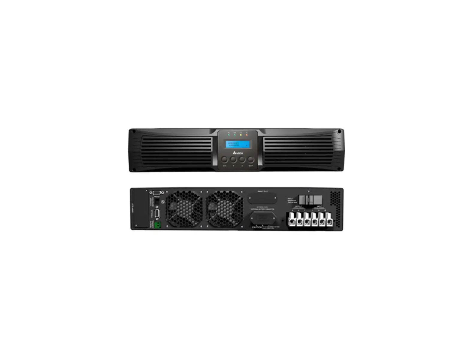
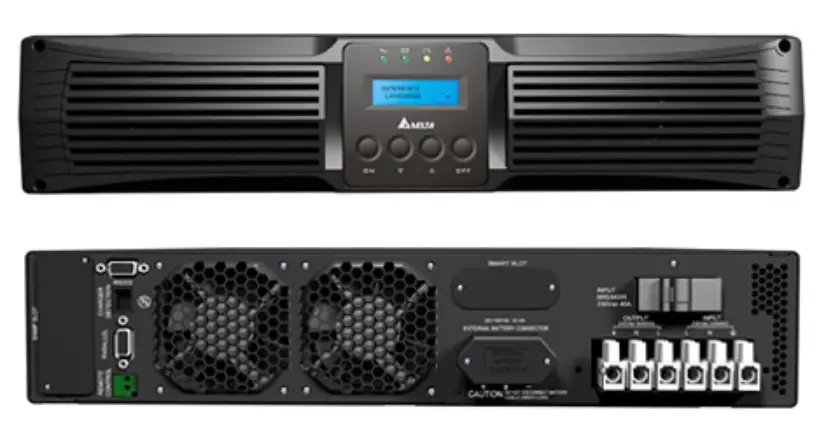
The Delta External Charger Box works as an external charger for a 5~20kVA on-line UPS. Its output power factor reaches to 0.97 and efficiency is up to 90%. The charger box provides wide range of charge voltage (120Vdc to 290Vdc) for you to adjust according to battery capacity. Working with a UPS, the charger box can charge lead-acid batteries and lithium batteries. Through the provided RJ45 cable, the charger box can send alarm signals to the UPS, which enhances the UPS’s monitor function.
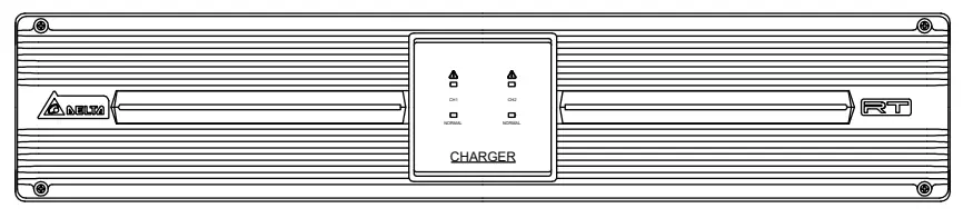
(Figure 1: Delta External Charger Box Front View)
Important Safety Instructions
Please read this user manual before operation and keep it for later reference. Failure to heed the manual will void the warranty.
- Install the charger box in a well-ventilated area. Do not expose it to rain, dust, and moisture. Keep it away from flammable gas or explosives.
- To protect the charger box from overheating and to ensure its reliability, do not block or cover its slits and openings.
- Do not put beverages on the charger box.
- All maintenance services must be performed by qualified personnel. Do not open or remove the cover of the charger box to avoid high voltage electric shock.
- The charger box must be well grounded due to a possible risk of current leakage.
- There is a risk of dangerous high voltage when the batteries are still connected to the charger box. Before maintenance of the charger box, do not forget to remove the input power cord and disconnect the battery cable to completely cut off the power source.
- Standard Compliance
CE and cTUVus (UL 62368-1)
FCC Class A
EN 61000-4-2, Level 4
EN 61000-4-6
EN 61000-4-3, Level 3
EN 61000-4-4, Level 4
EN 61000-4-5, 2kV (Common mode)
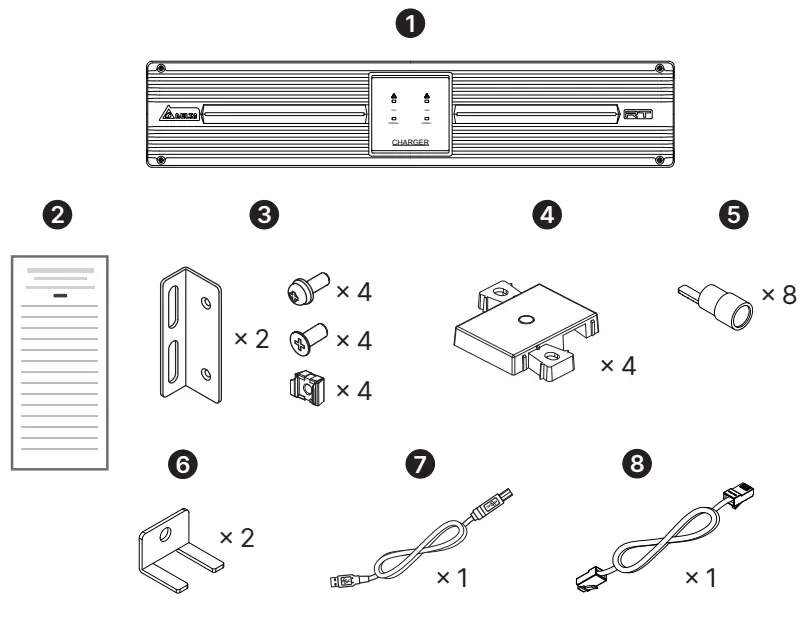
Package List
| No. | Item | Q’ty |
| 1 | Delta External Charger Box | 1 PC |
| 2 | Installation & Operation Quick Guide | 1 PC |
| 3 | Ear kit | 1 SET |
| 4 | Tower Stand Extender | 4 PCS |
| 5 | Terminal CU | 8 PCS |
| 6 | Bus bar for DC output | 2 PCS |
| 7 | Micro USB cable | 1 PC |
| 8 | RJ45 Cable | 1 PC |
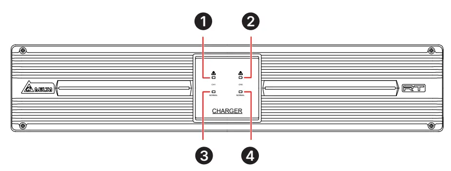
LED Indicators
(Figure 2: LED Indicators)
| LED No. | LED Status | Meaning |
| 1 | Off | CH1 works normally. |
| Flashing (Red) | CH1’s setting is abnormal. | |
| On (Red) | CH1 works abnormally. | |
| 2 | Off | CH2 works normally. |
| Flashing (Red) | CH2’s setting is abnormal. | |
| On (Red) | CH2 works abnormally. | |
| 3 | Off | CH1’s input power is abnormal. |
| Flashing (Green) | CH1’s input power is out of working range. | |
| On (Green) | CH1’s input power is normal. | |
| 4 | Off | CH2’s input power is abnormal. |
| Flashing (Green) | CH2’s input power is out of working range. | |
| On (Green) | CH2’s input power is normal. |
Rear Panel
| No. | Printing | Meaning | Description |
| 1 | RS 485 | RS 485 | For connection to the RS485 port on UPS. With a UPS, you can detect charger box information and control the charging voltage to synchronize with the UPS. RS 485 and Micro-USB can not be communicated at the same time. |
| 2 | MICRO USB | Micro-USB port | For configuring the charger box’s setting. |
| 3 | ID | DIP Switch | You can set communication ID by DIP Switch, please refer to Table 1 for ID setting. |
| 4 | DC OUTOPUT | Output terminal | For connection to battery cabinet. |
| 5 | AC INPUT | Input terminal | For connection to power input. |
(Figure 3: Rear Panel)
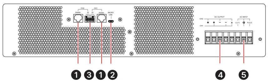
Table 1 Communication ID setting
DIP Switch |
FW | ID | ||||||
CH2 ID Set | CH1 ID Set | |||||||
| DIP1 | DIP2 | DIP3 | DIP4 | DIP5 | DIP6 | CH2 | CH1 | |
| OFF | OFF | OFF | OFF | OFF | OFF | 0 | ID11 | ID11 |
| OFF | OFF | ON | OFF | OFF | ON | 0 | ID12 | ID12 |
| OFF | ON | OFF | OFF | ON | OFF | 0 | ID13 | ID13 |
| OFF | ON | ON | OFF | ON | ON | 0 | ID14 | ID14 |
| ON | OFF | OFF | ON | OFF | OFF | 0 | ID15 | ID15 |
| ON | OFF | ON | ON | OFF | ON | 0 | ID16 | ID16 |
| ON | ON | OFF | ON | ON | OFF | 0 | ID17 | ID17 |
| ON | ON | ON | ON | ON | ON | 0 | ID18 | ID18 |
| OFF | OFF | OFF | OFF | OFF | OFF | 1 | ID19 | ID19 |
| OFF | OFF | ON | OFF | OFF | ON | 1 | ID20 | ID20 |
| OFF | ON | OFF | OFF | ON | OFF | 1 | ID21 | ID21 |
| OFF | ON | ON | OFF | ON | ON | 1 | ID22 | ID22 |
| ON | OFF | OFF | ON | OFF | OFF | 1 | ID23 | ID23 |
| ON | OFF | ON | ON | OFF | ON | 1 | ID24 | ID24 |
| ON | ON | OFF | ON | ON | OFF | 1 | ID25 | ID25 |
| ON | ON | ON | ON | ON | ON | 1 | ID26 | ID26 |
 NOTE:
NOTE:
- Please set different ID of CH1 and CH2.
- Please restart the charger box after FW ID is set, otherwise, FW ID setting is ineffective.
Installation and Configuration
Installation
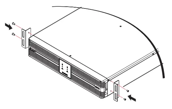
Rack Mounting:
- Attach the included bracket ears to the lateral mounting holes of the Delta external charger box. See Figure 4.
(Figure 4: Mount the Bracket Ears)
- Follow steps 1 to 2 to install the Delta External Charger Box in Delta’s rail kit (optional). See Figure 5.
Step 1 : Adjust the length of the rails according to your rack.
Step 2 : Tighten the rails’ nuts.
Step 3 : Fix the rails on your rack.
Step 4 : Install the Delta external charger box on your rack and tighten the provided screws.
(Figure 5: Install the Delta External Charger Box on Your Rack)
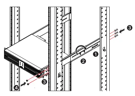
NOTE:
If you want to use a non-Delta rail kit, please only follow step 4.
Tower Mounting:
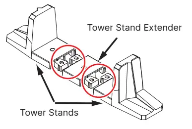
- Connect the provided tower stand extenders with the tower stands provided in the UPS’s carton (please take the UPS and the Delta external charger box’s size into consideration). See Figure 6.
(Figure 6: Connect the Tower Stand Extenders with the UPS’s Tower Stands)
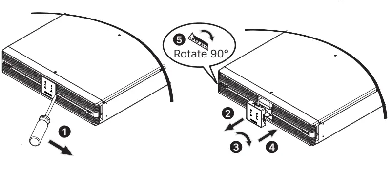
- Pull out the Delta external charger box’s control panel (1 & 2), rotate it 90° clockwise (3) and re-insert the control panel (4). After that, rotate the Delta logo nameplate 90° clockwise (5). See Figure 7.
(Figure 7: Rotate the Delta External Charger Box’s Control Panel & Delta Logo Nameplate)
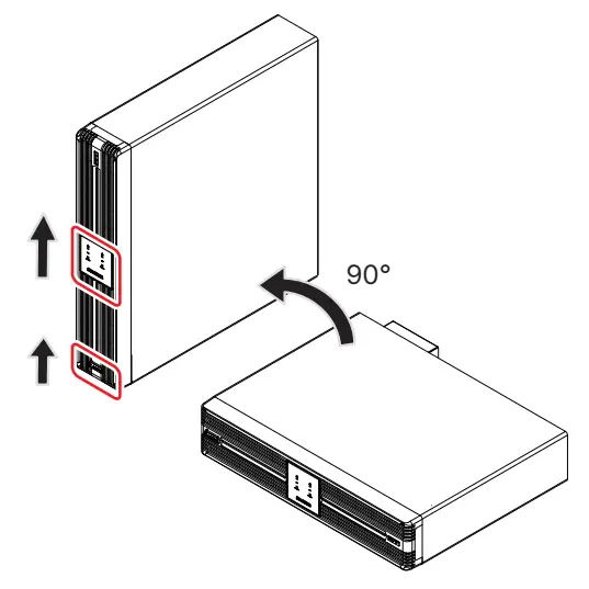
- Carefully lift the Delta external charger box upright with the Delta logo
 and the icon shown on the control panel facing up. A minimum of two people are required. See Figure 8.
(Figure 8: Place the Delta External Charger Box Upright)
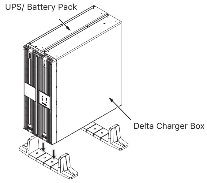
- Place the Delta external charger box and the UPS inside the tower stands. See Figure 9.
(Figure 9: Place the Delta External Charger Box and the UPS inside the Tower Stands)
Connect the Delta external charger box to UPS
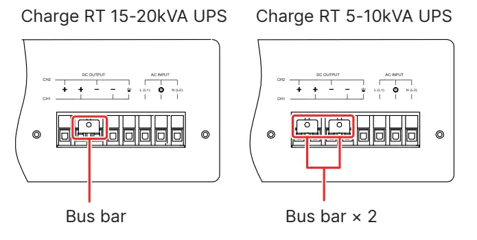
- Before installing input cables and output cables, fix the bus bar (provided in packing) first. See Figure 10.
(Figure 10: Fix Bus bar)
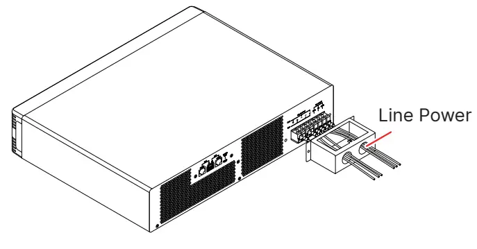
- Select proper input cables and cable gland, and compress the terminal CU in package to one end of the cable. Connect the terminal end to charger box’s input terminal block and the other end to line power. See Figure 11.
(Figure 11: Install Input Cables)
- When connecting the external charger box to the mains, it is highly recommended that you install the protective devices. Please refer to the table below.
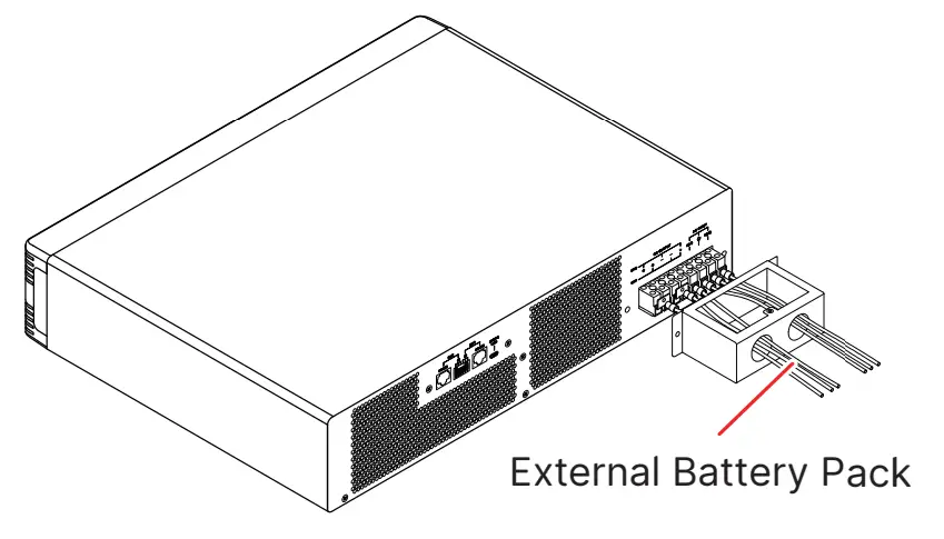
External Charger Box Model Suggested Protective Device CHG240-RT-1 250Vac/ 16A breaker CHG240-RT-2 250Vac/ 25A breaker - Select proper output cables and cable gland, and compress the terminal CU in package to one end of the cable. Connect the terminal end to charger box’s output terminal block and the other end to external battery pack. See Figure 12.
(Figure 12: Install Output Cables)
- For the specification of input/ output cables, please refer to below table.
Spec. / Capacity CHG240-RT-1/ CHG240-RT-2 Input/ Output Cables
(Rating Temperature 90°C)#12AWG (3 mm2) Tightening Torque 5.07kgf-cm (4.40 lb-in)
Configuration
Configure the charger box automatically
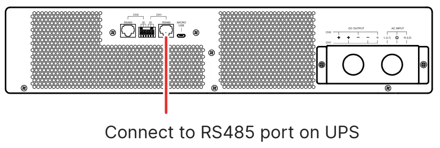
When the charger box is communicated with UPS (UPS need support charger box’s communication protocol) through RS485, charger box’s configuration is controlled by UPS, that is, follows UPS’s setting. Please refer to Figure 13 and Figure 14 for connection.
- Connect single charger box to UPS
(Figure 13: Connect Single Charger Box to UPS)
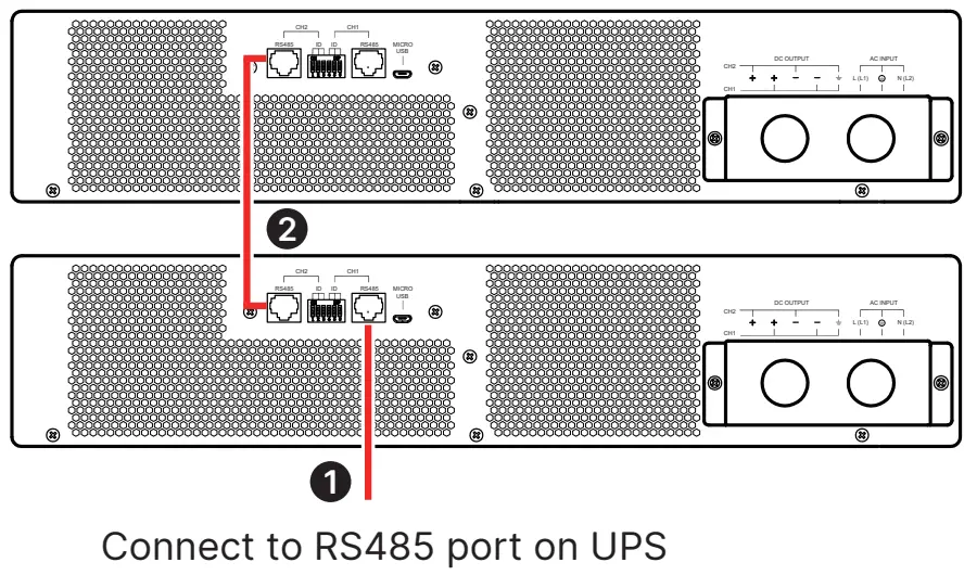
- Connect paralleled charger boxes to UPS
(Figure 14: Connect Paralleled Charger Boxes to UPS)
Troubleshooting
| LED Indicators | Problems | Solutions |
| LED flashes (Red) | The charger box’s setting is abnormal. | Check whether the configuration is correct. If all configuration is correct, please contact your local dealer or customer service representative. |
| LED on (Red) | The charger works abnormally. | |
| LED off (Green) |
| Check whether the input cables are firmly connected. If not, connect them. If the input cables are firmly connected but the LED still flashes or off, please contact your local dealer or customer service representative. |
| LED flashes (Green) | The input power is out of working range. |
Maintenance
Charger Box Cleaning:
- Regularly clean the charger box, especially the slits and openings, to make sure air flows freely through the charger box to avoid overheating.
Charger Box Inspection:
- Regularly check the charger box and inspect:
1. Whether the LED indicators are normal.
2. Whether the fan works normally and air flows freely through the charger box.
Fan:
- Higher temperatures shorten fan life. When the charger box is running, please check if the fan works normally and make sure the charger box is ventilated properly. If not, replace the fan.
NOTE:
Please ask your local dealer or customer service representative for more maintenance information. Do not perform maintenance if you are not trained for it.
Technical Specifications
| Delta External Charger Box | CHG240-RT-1 | CHG240-RT-2 | |
| Input | Voltage Range | 176~280Vac (Full load) | |
| Frequency | 40~70Hz | ||
| Current Rate | 10A | 20A | |
| Power Factor | > 0.97 | ||
| Protective Device | 15A fuse ( charger board) | ||
| Output | Output Power | 1600W | 3200W |
| Charging Voltage | 120 ~ 290Vdc | 120 ~ 290Vdc | |
| Charging Current (Maximum) | 8A | 16A | |
| Dimensions (W × D × H) | 440 × 395 × 88.5 mm (17.3″ × 15.6″ × 3.5″) | ||
| Weight | 5.7 kg (12.5 Ib) | 7.2 kg (15.8 Ib) | |
| Noise | < 45dBA@ < 30°C amb *1 | ||
| Environment | Operating Temperature | 0 ~ 55°C (32 ~ 104°F) *2 | |
| Relative Humidity | 0 ~ 95% (non-condensing) | ||
NOTE:
- *1 At a distance of 3.28 ft (1 meter) in front of the Delta external charger box.
- *2 De-rate to 75% load when the operating temperature is over 40°C (104°F), de-rate to 50% load when the operating temperature is over 50°C (122°F).
- Refer to the rating label for the safety rating.
- All specifications are subject to change without prior notification.
Copyright © 2022 by Delta Electronics Inc. All rights reserved. Changes may be made periodically to the information in this Quick Guide without obligation to notify any person of such revision or changes.
No. 501329680101
Version : V 1.1
Global Headquarter
Taiwan
Delta Electronics Inc.
39 Section 2, Huandong Road, Shanhua District, Tainan City 74144, Taiwan
T +886 6 505 6565
E [email protected]
Regional Office
The United States
Delta Electronics (Americas) Ltd. 46101 Fremont Blvd. Fremont, CA 94538
T +1 510 344 2157
E [email protected]
South America
Delta Electronics Brasil Ltda.
Estrada Velha Rio-São Paulo, 5300 – Eugênio de Melo – CEP 12247-001 São José dos Campos-SP-Brasil
T +55 12 39322300
E [email protected]
UK
Delta Electronics (UK) Ltd.
Eltek House Cleveland Road, Hemel Hempstead Industrial Estate, Hemel Hempstead, Hertfordshire, HP2 7EY
T +44 1442 219355
E [email protected]