![]() Wiring Safety Guide
Wiring Safety Guide
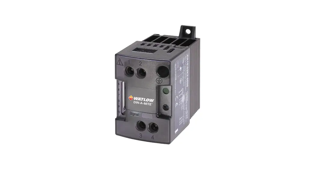
DIN-A-MITE® Power Controllers
Document Number:
2271-5649, 10-52315 Rev-
Safety Information
| CAUTION – Warning or Hazard that needs further explanation than the label on unit can provide. Consult User’s Guide for further information. | |
| Electrical Shock Hazard – Symbol (a lightning bolt in a triangle) precedes an electric shock hazard CAUTION or WARNING safety statement. | |
| ESD Sensitive product, use proper grounding and handling techniques when installing or servicing product. | |
| Do not throw in trash, use proper recycling techniques or consult manufacturer for proper disposal. | |
 | Unit is a Listed device per Underwriters Laboratories. It has been investigate to ANSI/UL® 508 standards for Industrial Control Switches and equivalent to CSA C22.2 #14. For more detail search for File E73741 on www.ul.com. |
| Unit is compliant with European Union directives. See Declaration of Conformity for further details on Directives and Standards used for Compliance. |
Safety Notes
![]() WARNING! To avoid damage to property and equipment, injury and loss of life, adhere to applicable electrical codes and standard wiring practices when installing and operating this product. Failure to doso could result in damage, injury and death.
WARNING! To avoid damage to property and equipment, injury and loss of life, adhere to applicable electrical codes and standard wiring practices when installing and operating this product. Failure to doso could result in damage, injury and death.![]() WARNING! All service including inspection, installation, wiring, maintenance, troubleshooting, fuse or other user-serviceable component replacement must be performed only by properly qualified personnel. Service personnel must read this manual before proceeding with work. While service is being performed, other, unqualified personnel should not work on the unit or be allowed in the immediate vicinity.
WARNING! All service including inspection, installation, wiring, maintenance, troubleshooting, fuse or other user-serviceable component replacement must be performed only by properly qualified personnel. Service personnel must read this manual before proceeding with work. While service is being performed, other, unqualified personnel should not work on the unit or be allowed in the immediate vicinity.![]() WARNING! When in use, the power controller is connected to dangerous voltages. Do not remove the protective covers without first disconnecting and preventing power from being restored while servicing the unit.
WARNING! When in use, the power controller is connected to dangerous voltages. Do not remove the protective covers without first disconnecting and preventing power from being restored while servicing the unit.![]() WARNING! Electric Shock Hazard: when the power controller has been energized, after shutting off the power, wait at least one minute for internal capacitors to discharge before commencing work that brings you in to contact with power connections or internal components.
WARNING! Electric Shock Hazard: when the power controller has been energized, after shutting off the power, wait at least one minute for internal capacitors to discharge before commencing work that brings you in to contact with power connections or internal components.![]() WARNING: The installation must be protected by fuses. Semiconductor fuses are classified for UL® as supplementary protection for semiconductor devices. They are not approved for branch circuit protection.
WARNING: The installation must be protected by fuses. Semiconductor fuses are classified for UL® as supplementary protection for semiconductor devices. They are not approved for branch circuit protection.![]() NOTE! The nominal current is specified for ambient temperatures at or below 50°C. Ensure the application design allows for adequate cooling of each power controller. The power controller must be mounted vertically. The cooling design must prevent air heated by one power controller from causing power controllers mounted above to exceed the ambient operating temperature limit. When power controllers are mounted side by side allow a minimum spacing of 15mm between them.
NOTE! The nominal current is specified for ambient temperatures at or below 50°C. Ensure the application design allows for adequate cooling of each power controller. The power controller must be mounted vertically. The cooling design must prevent air heated by one power controller from causing power controllers mounted above to exceed the ambient operating temperature limit. When power controllers are mounted side by side allow a minimum spacing of 15mm between them.![]() NOTE! Use only copper cables and wires rated for use at 75°C or greater.
NOTE! Use only copper cables and wires rated for use at 75°C or greater.
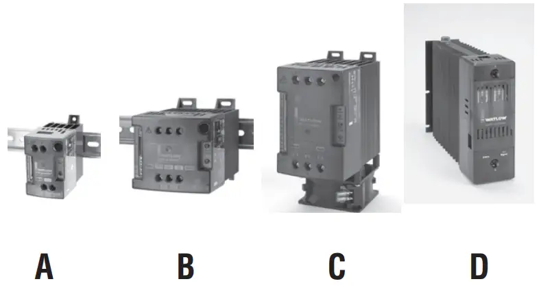
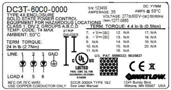
Identifying the Products
The product identification label includes not only the part number, but also the voltage and current ratings.
Environment
- Ambient operating temperature: 0 to 50°C. See User Manual for de-rating.
- Ambient temperature maximum varies depending on unit
- Mount power controllers vertically
- 5 to 90% RH (relative humidity), non-condensing
- Up to 6560 feet (2000m) above see level maximum
- Storage temperature. -40 to 85°C maximum
- Pollution degree: Installation Category III, Pollution degree 2
- Install away from direct sun light, conductive dust, corrosive gas, vibration, water and corrosive salts.
SCCR Rating
- SCCR Rating 200,000A up to 480 VAC
Terminal Identification
The following illustrations show the locations for line power, load, earth ground and signal connections.
Connection Locations DIN-A-MITE Style A
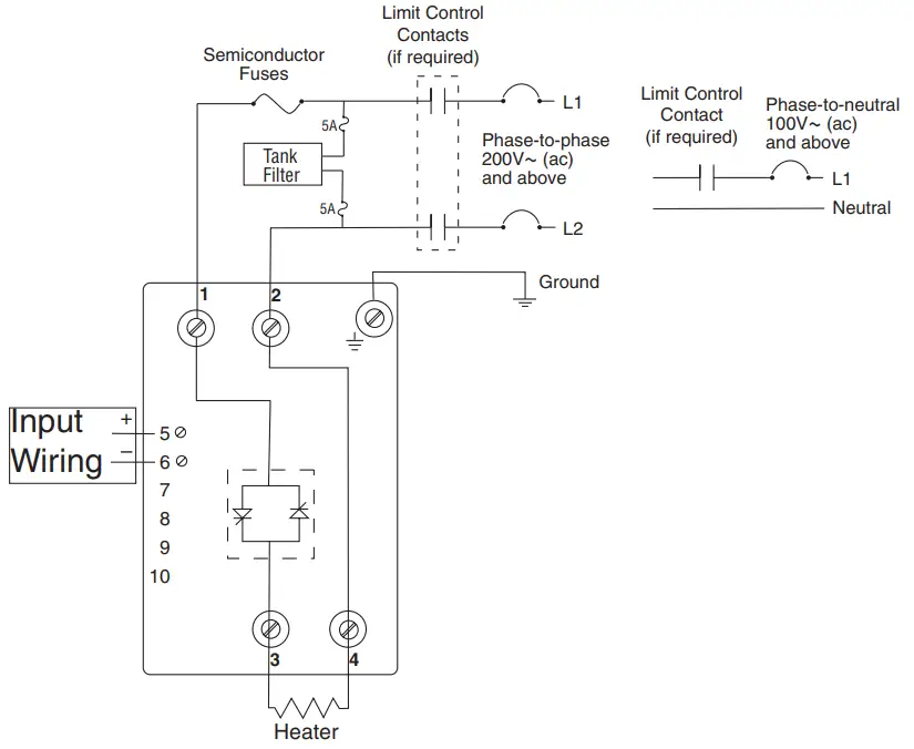
Line Connections
Line connections for DIN A are: 1, 2. Load connections are: 3, 4.
Grounding
Use a grounding con-ductor terminal plate (fork terminal) having upturned lugs or the equivalent to hold the wire in position. 6 mm2 (10 AWG) wire.
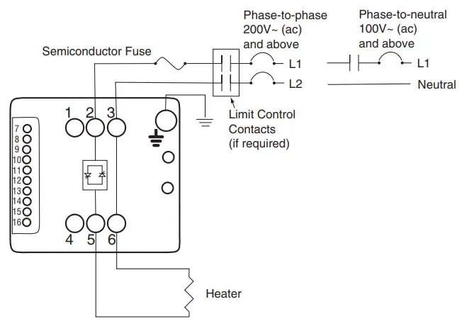
Connection Locations DIN-A-MITE Style B
Single-phase Output
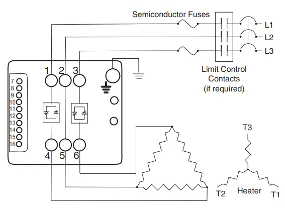
3-phase, 2-leg Output
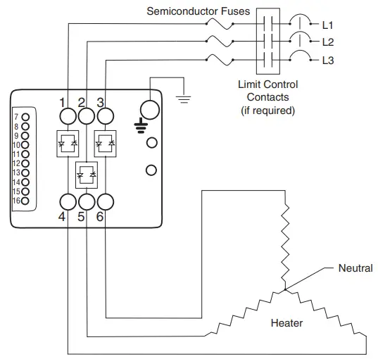
3 Phase, 3-leg Output
See user manual for current transformer connection options depending on control and alarm options and number of controlledlegs.
Grounding
Use a grounding conductor terminal plate (fork terminal) having upturned lugs or the equivalent to hold the wire in position. 6mm2 (10 AWG) wire.
Connection Locations DIN-A-MITE Style C: Single phase, Output
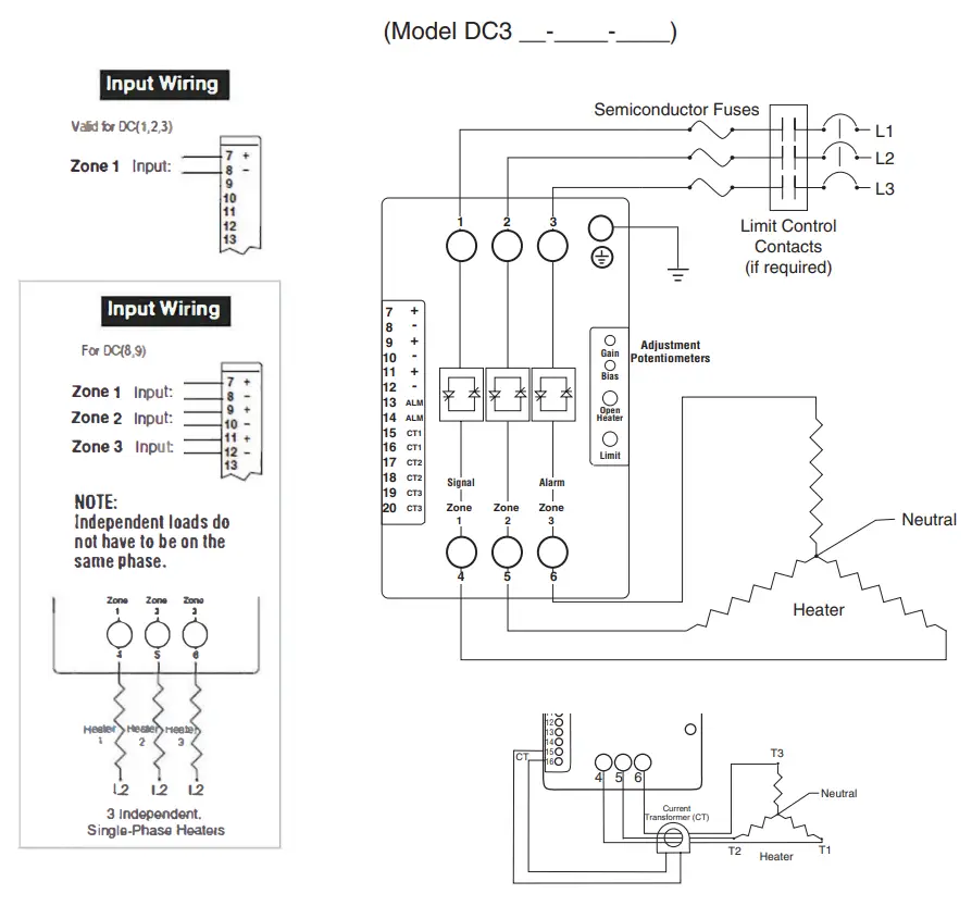
Connection Locations DIN-A-MITE Style C: 3-phase,2-leg Output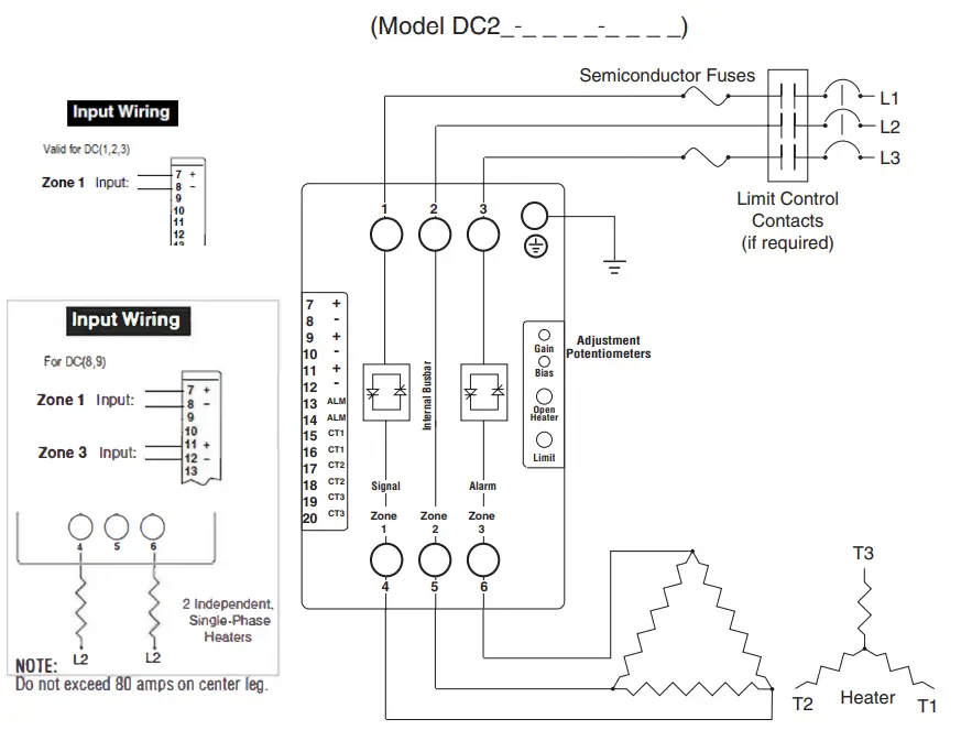 Connection Locations DIN-A-MITE Style C: 3-phase, 3-leg Output, Four Wire Wye
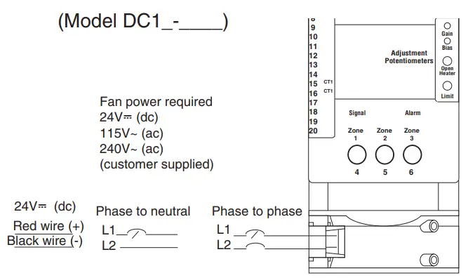
Connection Locations DIN-A-MITE Style C: Fan Cooled
NOTE:
Cooling fan terminals:
Quick connect1/8” push on, #16-14 AWG
Amp part no, 640929-1 or equivalent
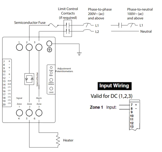
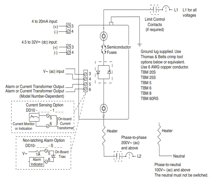
Connection Locations DIN-A-MITE Style D: Single Phase, Output and Input Wiring
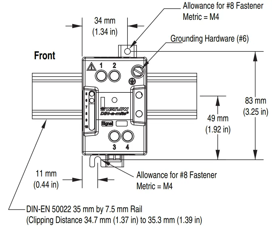
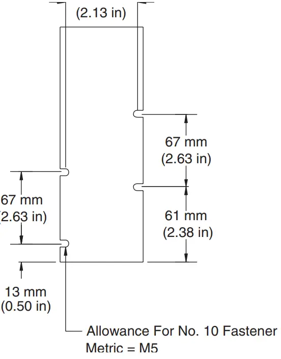
Mounting Information: DIN-A-MITE Style A
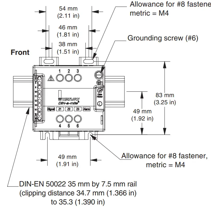
Mounting Information: DIN-A-MITE Style B
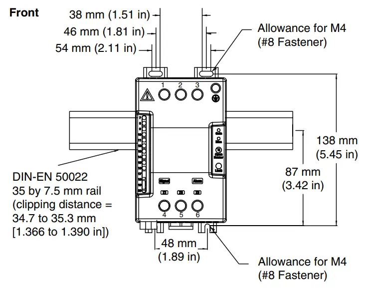
Mounting Information: DIN-A-MITE Style C -DCxT
Mounting Information: DIN-A-MITE Style C -DCx(0,1,2,3)
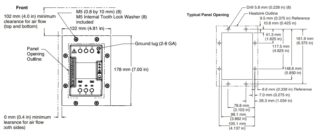
Mounting Information: DIN-A-MITE Style D
Wiring Instructions
Choose line and load wire size based on National Electric Code NFPA 70 or local electric codes for the current to be carried. When using 90°C wire, choose wire gauge based on 75°C table. See the table below for ground wire size recommendations.
| Branch Circuit Protection Rating | Ground Wire Size |
| 15 Amps | 14 AWG |
| 20 Amps | 12 AWG |
| 30 – 60 Amps | 10 AWG |
| 100 Amps | 8 AWG |
| 100 – 125 Amps | 6 AWG |
Wiring Instructions (Continued)
Line and Load Torquing Guidelines
- Properly torque line and load terminals, hold torque for 30 seconds
- Re-torque after 48 hours to minimize wire cold flow
- Re-torque line and load terminals every three to six months
Control Signal Torque
- 4.4 in.-lb. (0.5 Nm)
| Line Power, Load and Earth Ground Torque | ||
| Model Line/Load Driver | Line, Load & Earth Ground | Earth Ground Driver |
| DIN A 1/4 in. Flat blade | 12 in.-lbs. (1.4 Nm) | 1/4 in. Flat blade or hex |
| DIN B Pozi drive #2 | 12 in.-lbs. (1.4 Nm) | 1/4 in. Flat blade or hex |
| DIN C Pozi drive #2 | 24 in.-lbs. (2.7 Nm) | 1/4 in. Flat blade |
| DIN D 3/16 in. Hex | 85 in.-lbs. (9.6 Nm) | 3/8 in. Hex |
Terminal Descriptions
NOTE: Use recommended fusing to meet 200KA SCCR, type 1 and 2 approved. Other fusing limits SCCR to 5KA per UL508A and NEC guidelines.
DIN-A-MITE Style A Terminals
| Terminal | Function | Notes |
| 1 | Line 1 power | Switched by SCR |
| 2 | Line 2 power / neutral | Internal bus-bar to terminal 4 |
| 3 | T1 Load power | Output from SCR |
| 4 | T2 Load power | Internal bus-bar to terminal 2 |
| 5 | DC+ / AC command signal | DA10-xx(C,F)x-xxxx takes DC DA10-xxKx-xxxx takes AC |
| 6 | DC- / AC command signal | |
| 7, 8, 9, 10 | Not used / no connection |
DIN-A-MITE Style B, Style C Terminals
Power and Load Connections D(B or C)1x-xxxx-xxxx
| Terminal | Function | Notes |
| 1 | Not used / no connection | |
| 2 | Line 1 power | Switched by SCR |
| 3 | Line 2 power / neutral | Internal bus-bar to terminal 6 |
| 4 | Not used / no connection | |
| 5 | T1 Load power | Output from SCR |
| 6 | T2 Load power | Internal bus-bar to terminal 3 |
Power and Load Connections D(B or C)2x-xxxx-xxxx or D(B or C)8x-xxxx-xxx
| Terminal | Function | Notes |
| 1 | Line 1 power | Switched by SCR 1 |
| 2 | Line 2 power / neutral | Internal bus-bar to terminal 5 |
| 3 | Line 3 power | Switched by SCR 2 |
| 4 | T1 Load power | Output from SCR 1 |
| 5 | T2 Load power | Internal bus-bar to terminal 2 |
| 6 | T3 Load power | Output from SCR 2 |
NOTE: For D(B or C)(8 or 9) models. All zones can be on same phase input or multiphase input. Each zone is controlled independent of other zones.
Terminal Descriptions (Continued)
Command Signal Inputs DIN-A-MITE Style B and Style C
| Terminal | Models | Command Signal Input |
| 7 | Dx(1,2,3)x-xx(C,F)x-xxxx | DC+ |
| Dx(1,2,3)x-xxKx-xxxx | AC | |
| DC1x-xx(L,P)x-xxxx or DC(1,2,3)x-xxSx-xxxx | DC+ or Potentiomenter wiper | |
| Dx(8,9)x-xxCx-xxxx | Zone 1 DC+ | |
| Dx(8,9)x-xxKx-xxxx | Zone 1 AC | |
| 8 | Dx(1,2,3)x-xx(C,F)x-xxxx | DC- |
| Dx(1,2,3)x-xxKx-xxxx | AC | |
| Dx(8,9)x-xxCx-xxxx | Zone 1 DC- | |
| Dx(8,9)x-xxKx-xxxx | Zone 1 AC | |
| DC1x-xx(L,P)x-xxxx or DC(1,2,3)x-xxSx-xxxx | DC- or Potentiomenter CCW | |
| 9 | Dx(1,2,3)x-xxxx-xxxx | Not used / no connection |
| Dx9x-xxCx-xxxx | Zone 2 DC+ | |
| Dx9x-xxKx-xxxx | Zone 2 AC | |
| DX1x-xx(L,P)x-xxxx or DC(1,2,3)x-xxSx-xxxx | Potentiomenter CW | |
| 10 | Dx(1,2,3)x-xxxx-xxxx | Not used / no connection |
| Dx9x-xxCx-xxxx | Zone 2 DC- | |
| Dx9x-xxKx-xxxx | Zone 2 AC | |
| 11 | Dx(1,2,3)x-xxxx-xxxx | Not used / no connection |
| Dx8x-xxCx-xxxx | Zone 2 DC+ | |
| Dx8x-xxKx-xxxx | Zone 2 AC | |
| Dx9x-xxCx-xxxx | Zone 3 DC+ | |
| Dx9x-xxKx-xxxx | Zone 3 AC | |
| 12 | Dx(1,2,3)x-xxxx-xxxx | Not used / no connection |
| Dx8x-xxCx-xxxx | Zone 2 DC- | |
| Dx8x-xxKx-xxxx | Zone 2 AC | |
| Dx9x-xxCx-xxxx | Zone 3 DC- | |
| Dx9x-xxKx-xxxx | Zone 3 AC |
| Terminal | Models | Function |
| 13 | Dxxx-xxxx-(H,S)xxx | Alarm 100-240AC 300mA max. |
| Dxxx-xxxx-0xxx | Not used / no connection | |
| 14 | Dxxx-xxxx-(H,S)xxx | Alarm 100-240AC 300mA max. |
| Dxxx-xxxx-0xxx | Not used / no connection | |
| 15 | DC1x-xxLx-xxxx or Dxxx-xxxx-(H,S)xxx | Current transformer |
| All other models | Not used / no connection | |
| 16 | DC1x-xxLx-xxxx or Dxxx-xxxx-(H,S)xxx | Current transformer input |
| All other models | Not used / no connection | |
| 17,18,19,20 | DCxx-xxxx-xxxx | Not used / no connections |
| Terminal | Function | Notes / Model |
| 1 | Line 1 power | Switched by SCR |
| 2 | T1 Load power | Output from SCR |
| 3 | DC+ / AC command signal | DD10-xx(C,F)x-xxxx takes DC, DD10-xxKx-xxxx takes AC |
| 4 | DC- / AC command signal | |
| 5 | Not used / no connection | DD10-xxxx-0xxx |
| Current transformer output | DD10-xxxx-1xxx | |
| Alarm 100-240 AC 300mA max. | DD10-xxxx-Sxxx | |
| 6 | Not used / no connection Current transformer output Alarm 100-240 AC 300mA max. | DD10-xxxx-0xxx DD10-xxxx-1xxx DD10-xxxx-Sxxx |
200kA Fusing
Use recommended fusing to meet 200KA SCCR, type 1 and 2 approved. Other fusing limits SCCR to 5KA per UL508A and NEC guidelines.See “UL® and NEC® Requirements for Electrical Panel Assemblies Marked with Fault Current or SCCR” on the Watlow website for more information.
DIN-A-MITE Style A, Style B Recomended Fuses
| Recommended Fuse and Fuse Holder | |||||||
| Fuse | Watlow Semiconductor | Eaton® Semiconductor | Watlow Combination | Eaton® Combination | |||
| 20A | 17-8020 | FWC20A10F | 0808-0325-0020 | DFJ20 | |||
| 25A | 17-8025 | FWC25A10F | 0808-0325-0025 | DFJ25 | |||
| 32A | 17-8030 | FWP32A14F | 0808-0325-0030 | DFJ30 | |||
| 40A | 17-8040 | FWP40A14F | 0808-0325-0040 | DFJ40 | |||
| 50A | 17-8050 | FWP50A14F | 0808-0325-0050 | DFJ50 | |||
| Holders (single) | |||||||
| Fuse | Watlow | Mersen® (formerly Ferraz)® | Eaton® Combination | ||||
| 20A | 17-5110 | USM1i | – – – – – | ||||
| 25A | 17-5110 | USM1i | – – – – – | ||||
| 32A | 17-5114 | USM141i | – – – – – | ||||
| 40A | 17-5114 | USM141i | – – – – – | ||||
| 15 to 30A | 0808-0326-1530 | – – – – – | CH30J1i | ||||
| 35 to 60A | 0808-0326-3560 | – – – – – | CH60J1i | ||||
| Semiconductor Fuses for Applications Through 600V ~ (ac): | ||||
| Semiconductor Fuse Rating | Watlow Fuse P/N | Eaton® Fuse P/N | Watlow Holder P/N | Mersen® Holder P/N |
| 30A | 17-8030 | FWP30A14F | 17-5114 | USM141i |
| 40A | 17-8040 | FWP40A14F | 17-5114 | USM141i |
| 50A | 17-8050 | FWP50A14F | 17-5114 | USM141i |
| 63A | 17-8063 | FWP63A22F | 17-5122 | US22i |
| 80A | 17-8080 | FWP80A22F | 17-5122 | US22i |
| 100A | 17-4100 | FWP100A22F | 17-5122 | US22i |
| Combination Fuses for Applications Through 600V ~ (ac): | ||||
| Semiconductor use Rating | Watlow Fuse P/N | Eaton® Fuse P/N | Watlow Holder P/N | MersenR Holder P/N |
| 30A | 0808-0325-0030 | DFJ30 | 0808-0326-1530 | CH30J1i |
| 40A | 0808-0325-0040 | DFJ40 | 0808-0326-3560 | CH60J1i |
| 50A | 0808-0325-0050 | DFJ50 | 0808-3026-3560 | CH60J1i |
| 63A | 0808-0325-0060 | DFJ60 | 0808-3026-3560 | CH60J1i |
| 80A | 0808-0325-0080 | DFJ80 | 0808-0326-7010 | J60100-1CR |
| 100A | 0808-0325-0100 | DFJ100 | 0808-0326-7010 | J60100-1CR |
DIN-A-MITE Style D Replacement Fuses
Watlow 0808-0096-0000 Eaton 170N3437
Torque for Replacement Fuses 40 in-lbs (4.52 Nm)
EMC Filters
Filters for EMC conducted emissions compliance.
| Description | Crydom® Filter | Watlow Filter |
| Single-phase, 230V~ (ac) | 1F25 | 14-0019 |
| Three-phase, 440V~ (ac) | 3F20 | 14-0020 |
Agency Approval and Regulatory
- cULus® 508 Listed File E73741
- cULus® Listed to C22.2 No. 14
- IP 20 with all covers in place
- Utilization Category: AC-51, AC-55b, AC-56a
- SCCR rating 200,000A up to 480 VAC
- DCxT models UL® 50 Type 4x approved Class 1 Division 2 Groups A, B, C, D Temperature Code T4 Hazardous Locations cULus® ANSI/ISA 12.12.01 Listed file E 184390
- CE and UKCA declarations available upon request
User Manuals
Complete user manuals are available at
User manuals: www.watlow.com/kb/DINA; www.watlow.com/kb/DINB;
www.watlow.com/kb/DINC; www.watlow.com/kb/DIND
Technical Assistance
If you encounter a problem with your Watlow controller, review your configuration information to verify that your selections are consistent with your application: inputs, outputs, alarms, limits, etc. If the problem persists, you can get technical assistance from your local Watlow representative (see back cover), by e-mailing your questions to [email protected] or by dialing +1 (507) 494-5656 between 7 a.m. and 5 p.m. Central Time USA & Canada. Ask for an Applications Engineer. Please have the complete model number available when calling.
How to Reach Us
| Watlow Electric Manufacturing Company 12001 Lackland Road St. Louis, MO 63146 Sales: 1-800-WATLOW2 Manufacturing Support: 1-800-4WATLOW | Email: [email protected] Website: www.watlow.com From outside the USA and Canada: Tel: +1 (314) 878-4600 Fax: +1 (314) 878-6814 |
![]()
![]()
![]()
References
 UL Solutions
 Global Supplier of Industrial Electric Thermal Solutions | Watlow
-
DIN-A-MITE® Style A Solid-State Power Controller User's Guide | Watlow
-
DIN-A-MITE® Style B Solid-State Power Controller User's Guide | Watlow
-
DIN-A-MITE® Style C Solid-State Power Controller User's Guide | Watlow
-
DIN-A-MITE® Style D Solid-State Power Controller User's Guide | Watlow


