![]()
everyday genius
MT7921K Install User Guideline
Confidetial B
Version: VO. 5
Release Date: 2021-12-30
© 2022 MediaTek Inc.
This document contains information that is proprietary to MediaTek Inc. Unauthorized reproduction or disclosure of this information in whole or in part is strictly prohibited. Specifications are subject to change without notice.
Document Revision History
| Version | Date | Author | Change List |
| V0.1 | 20201214 | Jane | Initial draft release. |
| V0.2 | 20210109 | Jane | Added antenna set 4 information — ” RFMTA311020EMMB301 V02″ |
| IV0.3 | 20210527 | Added antenna set 5 information — ” JR2000340-1″ | |
| I V0.4 | 20210713 | Added antenna set 6, 7 information — ” LA9RF059-CS-H”, “14008-02650500” I | |
| I V0.5 | 20211230 | Added antenna set 8, 9 | |
System overview
General Description
MT7921K chip is a highly integrated single-chip which have a built-in 2×2 dual-band wireless LAN and Bluetooth combo radio. WiFi works on the ISM band, which means many other devices such as microwave ovens, radar, and Bluetooth use the same frequencies and channels as WiFi devices.
Therefore, governments make regulations to avoid interference between devices. The specifications include usable channels, scan rule, and transmit power.
Driver install
2.1 How to install the driver
Please follow the procedure listed below to install the driver
- 1st: Update Windows security package to register signature mechanism.
- 2nd: Install Windows driver.
2.1.1 Windows Security for the new signature mechanism
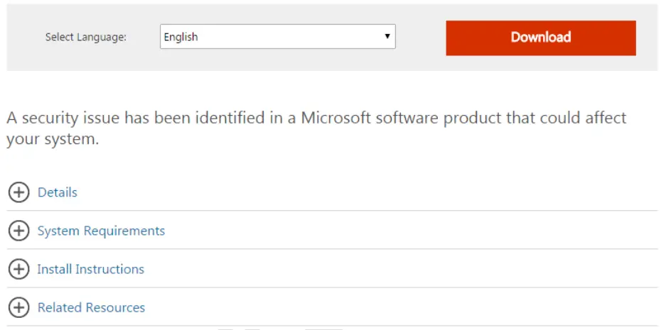
If you are the 1st time use this driver, you should update Windows Security for a new signature mechanism at first. Please follow the below link to install this software.
https://www.microsoft.com/en-us/download/details.aspx?id=46148
For Windows 7 x64 example:
2.1.2 Windows 10 install note
If the manufacturer can’t install the driver in Windows 10 due to a driver integrity check, try to disable the integrity check to allow installation.
- Disable Driver Integrity Check
- Open cmd as Administrator.
- Execute ‘bcdedit /set nointegritychecks on’
- Reboot
- Then install again. If still fail, try to do ‘Disable Secure Boot’ below.
NOTE: Re-enable the driver integrity check by executing ‘bcdedit /set no integrity checks off’ and then rebooting.
- Disable Secure Boot
Please refer to: https://docs.microsoft.com/en-us/windows-hardware/manufacture/desktop/disabling-secure-boot
2.1.3 Install Windows driver
MT7921K supports the PCI-E interface. According to the interface type of MT7921K, please refer to the steps shown below to install the Windows driver:
PCI-E interface: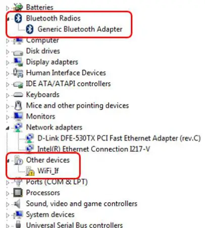
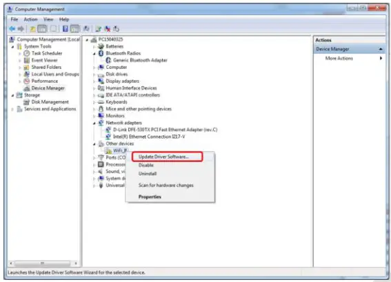
- Connect DUT to PC/NB and check Windows Device Manager.
- Window Device Manager would discover DUT shows “Generic Bluetooth Adapter”(BT device) and “WiFi_lr(WiFi device).

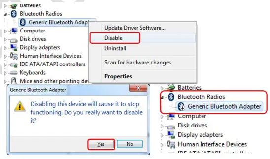
- Right-click the “Generic Bluetooth Adapter” BT device and select disable as follows

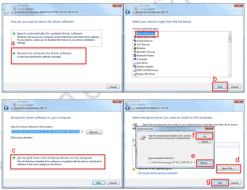
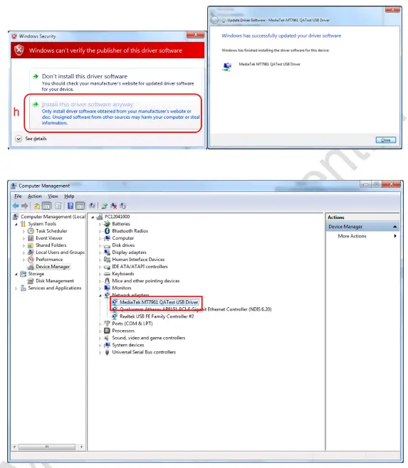
- Right-click on “WiFi_If” Wifi device and Update Driver

- According to the host’s Windows’ OS to select and install
General Information & Integration Instructions
1.1 General Description of MT7921K
| Product | 2TX 11ax (WiFi6E) + BT/BLE Combo Card |
| Brand | MediaTek |
| Model | MT7921K |
| Power Supply Rating | 3.3Vdc from host equipment |
| Modulation Type | GFSK, π/4-DQPSK, 8DPSK for FHSS CCK, DQPSK, DBPSK for DSSS 64QAM, 16QAM, QPSK, BPSK for OFDM 256QAM for OFDM in 11ac mode and VHT20/40 in 2.4GHz 1024QAM for OFDMA in 11ax HE mode |
| Modulation Technology | BT EDR: FHSS BT LE: GFSK WLAN: DSSS, OFDM, OFDMA |
| Transfer Rate | BT EDR: up to 3 Mbps BT LE: up to 2 Mbps 802.11b: up to 11 Mbps 802.11a/g: up to 54 Mbps 802.11n: up to 300 Mbps 802.11ac: up to 866.7 Mbps 802.11ax: up to 1201.0 Mbps |
| Operating Frequency | BT EDR: 2402MHz ~ 2480MHz BT LE 1M: 2402MHz ~ 2480MHz BT LE 2M: 2404MHz ~ 2478MHz 2.4GHz: 2.412 ~ 2.472GHz 5GHz: 5.18~5.32GHz, 5.50~5.72GHz, 5.745 ~ 5.825GHz 6GHz: 5.955 ~ 6.415GHz, 6.435 ~ 6.525GHz, 6.525 ~ 6.875GHz, 6.875 ~ 7.115GHz |
| Number of Channel | BT EDR: 79 BT LE: 40 2.4GHz: 802.11b, 802.11g, 802.11n (HT20), VHT20, 802.11ax (HE20): 13802.11n (HT40), VHT40, 802.11ax (HE40): 9 5GHz: 802.11a, 802.11n (HT20), 802.11ac (VHT20), 802.11ax (HE20): 25 802.11n (HT40), 802.11ac (VHT40), 802.11ax (HE40): 12 802.11ac (VHT80), 802.11ax (HE80): 6 6GHz: 802.11ax (HE20): 59 802.11ax (HE40): 29 802.11ax (HE80): 14 |
1.1 Antenna information
The antennas mentioned below are covered in the certification scope and the HOST can only be used with the following antennas:
Original
| Ant. Set | RF Chain No. | Brand | Model | Ant. Net Gain (dBi) | Freq. Range (GHz) | :0 | Connector Type | Cable Length (mm) | Cable Loss (dB) | Excluding Cable Loss Ant. Gain (dBi) |
| 1 | Chain() | Contact | AN2450- 49028RS | 2.42 187 | 2.4-2.4835 115-5.85 | Dipole | R-SMA | 150 | 24-2.48356Hz : 0.5 5.15-5.856Hz : 0.8 | 2.92 4.67 |
| Chain’ | Cortec | AN2450- 49028RS | 2.42 3.87 | 2.4-2.4835 5.15-5.85 | Dipole | R-SMA | 150 | 2.4-2.48356Hz : 0.5 5.15-5.85GHz: 0.8 | 2.92 4.67 | |
| 2 | Chain() | PSA | RFMTA340718E MLB302 | 118 4.92 | 2.4-2.4835 5.15-4.85 | PIFA | i-pex(MHF) | 200 | included cable loss | – |
| Chainl | PSA | RFMTA340718E MLB302 | 3.18 4.92 | 2.4-2_4835 5.15-5.85 | PIFA | i-pex(MHF) | 200 | included cable loss | – | |
| 3 | Chain() | PSA | RFMTA311020E MMB301 | .71 4.82 3.31 | 2.4-2_4835 5.155.85 5.92-7.125 | PIFA | Apex(MHF) | 200 | – | – |
| Chanel | RFMTA311020E MM6301 | 1.71 4.82 3.31 | 2.4-24835 1155.85 5.92-7.125 | PIFA | i-pex(MHF) | 200 | ||||
| ,11 | Cha:^0 | PU | RFMTA311020E MMB301 VO2 | 1.71 4.82 4.78 4.29 4.61 4.09 | 2.4-24835 5.15-5.85 5.925-6.425 8.425-6.525 8.525-6.875 8.875-7.125 | PI FA | i-pex(MHFI | 8 (%1 | – | |
| “: 71.in :.’ 1 – 71:71 ‘, ‘ | 1.71 4.82 4.76 4.29 4.61 4.09 | 2.4-2.4835 5.15-5.85 5.925-4.425 8.425-6.525 8.525-4.875 8.875-7.125 | PIFA | i-pex(MHF) | 200 | – | ” |
| 5 | Chain() | VSO | JR2000340-1 | 1.62 3.2 3.93 3.61 3.61 3.14 | 2.4-24835 5.15-5.85 5.925-6.425 6.425-6.525 6.525-6.875 6_8757.125 | Dipole | RP SMA PLUG | 40 | – | – |
| Chainl | VSO | JR2Q00140-1 | 1.82 3.2 3.93 3.61 3.61 3.14 | 2.4-2_4835 5.15-5.85 5.925-6.425 6.425-6.525 6.525-6.875 6.875-7.125 | Dipole | RP SMA PLUG | 40 | – | – | |
| 6 | Chain() | Luxshare -ICT | LA9RF059-CS-H (Main) | 0.3 1_3 1_2 | 2.4-2A835 5.15-5.85 5.825-7.125 | Dipole | RP SMA PLUG | 925 | – | – |
| Chanel | Luxshare -ICT | LA9RF059-CS-H (Aux) | -1.10 -1.10 1.4 | 2.4-2A835 5.15-5.85 5_925-7.125 | Dipole | RP SMA PLUG | 876 | – | – | |
| N- | Chain() | ASUS | 14008-02850500 Man ant | 1.03 2.07 2.80 | 2.4-2A835 5.15-5.85 5_925-7.125 | Dipole | RP SMA PLUG | 800 | – | – |
| Chai n 1 | ASUS | 14008-02850500 Aux ant. | 227 2.01 3.08 | 2. 4-2A835 5.15-5.85 5,925-7.125 | Dipole | RP SMA PLUG | 800 | – | – |
| 8 | Chain0 | MSI | WA-P-LE-02-045 (Main) | 2.24 2.88 3.01 -1.23 -1.96 -3.68 | 24-2_4835 5.15-5.85 5.925-6.425 8.425-8.525 8.525-8.875 8.875~7.125 | PIFA | IPEX-4L | 190 | 2.4-2.4835GHz: 0/2 5.15-5.85GHz: 1.12 5.925-6.425 GHz: 1.21 8.4256.525 GHz: 1.19 8.5258.875 GHz: 1.21 8.8757.125 GHz: 1.29 | 2_96 3.8 4.22 0_04 0_15 2.39 |
| Chain1 | MSI | IVA-P-LE-02-046 (Aux) | -2.96 1.18 0.99 -2.31 -2.54 -7.44 | 2_4–2A835 5.15,6.85 5.925-6.425 6.4256.525 6.5258.875 8.8757.125 | PIFA | IPEX-41. | 325 | 2.4-2.4835G Hz: 1_3 5.15–5.85GHz: 2.16 5.9256.425 GHz: 2.2 8.4256.525 GHz: 2.22 8.5258.875 GHz: 8.8757.125 GHz: 2.34 | 1_66 132 319 0.06 029 -51 |
Newly
| Ant. Set | RF Char No. | Brand | Mc.:. c-. | Ant. Net Gain : oBi) | Freq. Range (GHz) | Ant. Type. | Connector Type | Cable Length . unn-il | Cable Loss icIBI ‘ | Exci-uc ng Cable Loss Ant. Gain (cBi) |
| Chang | PSA | RFP0A4808321 MMB701 | -13.20 -13.87 -13.67 -13.09 | 5.925-8.425 8.425-8 525 8.525-6.875 8.875-7.125 | Dipole | IPEX | 320 | – | – | |
| 1:1 I 1 | PSA | RFP0A4808321 MMB701 | -13.20 -13.67 -13.87 -13.09 | 5.925-8.425 8.425-6.525 8.525-8.875 8.875-7.125 | Dipole | IPEX | 320 | – | – | |
| 10 | Cha ^0 | CO CL | RFMTA42 1 2 301 MMB 7: ‘ | -13.92 -13.91 -13.91 -14.48 | 5.925-8.425 8.425-8 525 8.525-8.875 8.875-7.125 | PIFA | IPEX | 300 | – | – |
| PSA | RFMTA42 ‘ .1 . : MMB7: • | -13.92 -13.91 -13.91 -14.48 | 5.925-8.425 8.425-8 525 8.525-6.875 8.875-7.125 | PIFA | IPEX | 300 | – | – |
Please note that the above antennas are custom made for the MediaTek MT7921K module and are not listed in Walsin Technology Corp standard catalogs. For the purchase of these antennas, please contact Walsin Technology as listed below directly. Only the above antennas are tested for compliance with the FCC rules, and all other antennas (even the same type with lower gain) will require a re-assessment to be used with this module.
Contact info for above-certified antennas:
Company/Dept.: Walsin Technology Corp./ Antenna Business Dept.
Contact window: Andrew Lin
Tel: +886-3-475-8711 # 8172
Cell phone: +886-938-286-596
Email address: andrewlinepassivecomponent.com
URL link: http://www.passivecomponent.com/zh-hant/products/antenna/
3.3 Host Integration instructions
The product is designed to be used with the “NGFF (Next Generation Form Factor) M.2 2230” PCI-E Bus, please install the module into an M.2 2230 PCI-E slot.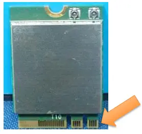
3.4 Host product testing guidance
HOST must follow the specific restrictions listed in the “3.5 Regulatory notes” section below and section 3 of KDB996369 D04 V02 Module Integration Guide v01, to verify that the host product meets all the applicable rules.
3.5 Regulatory notes
Federal Communication Commission Interference Statement
This device complies with Part 15 of the FCC Rules. Operation is subject to the following two conditions: (1) This device may not cause harmful interference, and (2) this device must accept any interference received, including interference that may cause undesired operation.
This equipment has been tested and found to comply with the limits for a Class B digital device, pursuant to Part 15 of the FCC Rules. These limits are designed to provide reasonable protection against harmful interference in a residential installation. This equipment generates, uses, and can radiate radio frequency energy and, if not installed and used In accordance with the instructions, may cause harmful interference to radio communications. However, there is no guarantee that interference will not occur in a particular installation. If this equipment does cause harmful interference to radio or television reception, which can be determined by turning the equipment off and on, the user is encouraged to try to correct the interference by one of the following measures:
Reorient or relocate the receiving antenna.
Increase the separation between the equipment and receiver.
Connect the equipment into an outlet on a circuit different from that to which the receiver is connected.
– Consult the dealer or an experienced radio/TV technician for help.
FCC Caution: Any changes or modifications not expressly approved by the party responsible for compliance could void the user’s authority to operate this equipment.
This transmitter must not be co-located or operating in conjunction with any other antenna or transmitter.
This device meets all the other requirements specified in Part 15E, Section 15.407 of the FCC Rules.
Radiation Exposure Statement:
This equipment complies with FCC radiation exposure limits set forth for an uncontrolled environment. This equipment should be installed and operated with a minimum distance of 20cm between the radiator & your body.
This module is intended for OEM integrators only. Per FCC KDB 996369 D03 OEM Manual v01 guidance, the following conditions must be strictly followed when using this certified module:
KDB 996369 D03 OEM Manual v01 rule sections:
2.2 List of applicable FCC rules
This module has been tested for compliance with FCC Part 15 Subpart C (15.247) and Subpart E (15.407). The device is tested for compliance as a low-power indoor client device within a 5.925-7.125 GHz band.
2.3 Summarize the specific operational use conditions
The module is tested for standalone mobile RF exposure use conditions. Any other usage conditions such as co-location with another transmitter (s) will need a separate reassessment through a class II permissive change application or new certification.
This module is authorized for Low Power Indoor Client applications only; the final host product must be for indoor operations only.
Further operation restrictions on the host product include:
*Prohibited for control of or Communications with unmanned aircraft systems.
2.4 Limited module procedures Not applicable.
2.5 Trace antenna designs Not applicable.
2.6 RF exposure considerations
This equipment complies with FCC mobile radiation exposure limits set forth for an uncontrolled environment. This equipment should be installed and operated with a minimum distance of 20cm between the radiator & your body. A separate SAR/Power Density evaluation is required to confirm compliance with relevant FCC portable RF exposure rules.
2.7 Antennas
The following antennas have been certified for use with this module.
Original
| RF Chain | Brand | No. Model | Ant. Net Gain (dBi) | Freq_ Range (GHz) | Ant Type | Connect. Type | Cable Length (mm) | Cable Loss (dB) | Excluding Cable Loss Ant. Gain (dBi) | |
| 1 | Chain() | Co rte : | AN2450- 49028RS | 2.42 3.87 | 2.4-2_4835 5.15-5.85 | Dipole | R-S MA | 150 | 2.4-2.4835GHz : 0.5 5.15-5.85GHz :0.8 | 2.92 4.67 |
| Chaim | Co rec | AN2450- 4902BRS | 2.42 3.87 | 2.4-2.4835 5.15-5.85 | Dipole | R-SMA | 150 | 2.4-2.48356Hz : 0.5 5.15-5.85GHz: 0.8 | 2.92 4.87 | |
| 2 | Chain() | PSA | RFMTA340718E MLB302 | 3.18 4.92 | 2.4-2.4835 5- 5.15.85 | PIFA | i-poo(MHF) | 200 | included cable loss | |
| Chaim | PSA | RFMTA340718E MLB302 | 3.18 4.92 | 2.4-2_4835 5.15-5.85 | PIFA | i-pex(MHF) | 200 | included cable loss | ||
| Chaine | PSA | RFMTA311020E MMB301 | 1.71 4.82 3.31 | 2.4-2A835 5.15-5.85 5.92-7.125 | PIFA | i-pex(MHF | – | |||
| Cha – ‘ | PSA | RFMTA311020E MMB301 | 1.71 4.82 3.31 | 2.4-2.4835 5.15-5.85 5.92-7.125 | PIFA | i-pex(MHF | – – – | – | . | |
| Cha -D | PSA | RFMTA311020E MMB301 VO2 | 1.71 4.82 4.76 4.29 4.61 4.09 | 2.4-2_4835 5.15-5.85 5.925-43.425 6.425-6.525 6.525-6.875 6_875-7.125 | PIFA | i-pex(MHF) | 200 | |||
| Cha – • | PSA | RFMTA311020E MMB301 VO2 | 1.71 4.82 4.76 4.29 4.61 4.09 | 2.4-24835 5.15-5.85 5.925-6.425 6.425-6.525 6.525-6.875 6_875-7.125 | PIFA | i-pex(MHF) | 200 | . |
| 5 | Chain) | VSO | JR2000340-1 | 1.62 3.2 3.93 3.61 3.81 3.14 | 2.4-24835 5.15-5.85 5.925-4.425 8425-6.525 6.525-4.875 6.875-7.125 | . DIP°ie | RP SMA PLUG | 40 | – | – |
| Chainl | VSO | JR2Q03340-1 | 1.62 3.2 3.93 3.61 3.61 3.14 | 2.4-24835 5.15-5.85 5_925-4.425 8.4254.525 6.525-6.875 6.875-7.125 | D pole | RP SMA PLUG | 40 | – | – | |
| 6 | Chaim) | Luxshare -ICT | LAQRF059-CS-H (Man) | 0.3 1.3 1_2 | 2.4-24835 5- 5.15.85 5_925-7.125 | Dipole | RP SMA PLUG | 925 | – | – |
| Chain1 | Luxshare -ICT | Uk9RF059-CS-H (Aux) | -1.10 • -1.10 1.4 | 2.4-2.4835 5.15-5.85 5.925-7.125 | Dipole | RP SMA PLUG | rot vi” | . | _ | |
| I N. 1 | Chain0 | ASUS | 14008-02850500 Man ant | 1.03 2.07 2.80 | 2.4-2.4835 5.15-5.85 5.925-7.125 | Dipole | RP SMA PLUG | 800 | . | _ |
| C hain 1 | ASUS | 14008-02650500 Aux ant. | 2.27 2.01 3.08 | 2.4-2_4835 5.15-5.85 5_925-7.125 | Dipole | RP SMA PLUG | 800 | _ | _ |
| 5 | Chain° | MSI | WA-P-LE-02-045 (Main) | 2.24 2.68 3.01 -1.23 -1.96 -3.88 | 2 4-2A835 5.15-5.85 5.925-6.425 6.425-6 525 6.525-6.875 8.875-7.125 | PIFA | IPEX-4L | 190 | 2.4-2.4835GHz: 0/2 5.15-5.856Hz: 1.12 5.925-6.425 GHz: 1.21 8.425-6.525 GHz: 1.19 8.525-6.875 GHz: 121 6.875-7.125 GHz: 1.29 | 8 Pei |
| Chaim | MSI | WA-P-LE-02-048 (Aux} |
| 2.4-2.4835 5.15-5.85 5.925-6.425 6.425-6 525 6.525-6.875 6.875-7.125 | PIFA | IPEX-4L | 325 | 2.4-2.4835GHz: 1.3 5.15-5.85GHz: 2.16 5.925-6.425 GHz: 2.2 8.425-8.525 GHz: 2.23 8.525-8.875 GHz: 2.25 8.875-7.125 GHz: 2.34 |
Newly
| Ant. Set | RF Chart No. | Brand | Model | Ant. Net Gain (dB’) | reqd . Range (GHz) | Ant. Type | Connector Type | Cable Length (mm) | Cable Loss (dB) | Emitting Cable Loss Ant. Gain (dal) |
| 9 | Chane | PSA | PFPCA4606321 MMB701 | -13.20 -13.87 -13.87 -13.09 | 5.925-6.425 8.425-6 525 8.525-6.875 8.875-7.125 | Dipole | IPEX | 320 | – | |
| Chant | PSA | RFPCA4606321 MMB701 | -13.20 -13.87 -13.87 -13.09 | 5.925-8.425 8.425-6.525 8.525-6.875 8.875-7.125 | ci.toffe | IPEX | 3’0 | – | ||
| 10 | Char)0 | PSA | RFMTA421230I MMB701 | -13.92 -13.91 -13.91 -14.46 | 5.925-0.425 8.425-6 525 6.525-6.875 6.8757.125 | PIFA | IPEX | 300 | ||
| Chant | PSA | RFMTA421230I MMB701 | -13.92 -13.91 -13.91 -14.48 | 5.925-8.425 8.425-6 525 8.525-8.875 6.875-7.125 | PIFA | IPEX | 300 |
Note1: Use of other antenna types or the same type of antenna with higher gain than listed above must perform additional testing and appropriate permissive change approval. Note2: In the 5.925-7.125GHz band, the use of other similar type antennas and the antenna gain, not higher/lower than listed above may only require a C1PC without any additional testing/submission.
Note3: Additional testing/submission (C2PC) will require if the device has not met the antenna and RF exposure requirements.
Note4: Contact MTK for additional guidance, if choose to use different antenna types or higher/lower gain antennas in the end system.
IMPORTANT: The final host product must have an integrated antenna that is not removable by the end-user.
2.8 Label and compliance information
The final end product must be labeled in a visible area with the following: “Contains FCC ID: RAS-MT7921K”. The grantee’s FCC ID can be used only when all FCC compliance requirements are met.
2.9 Information on test modes and additional testing requirements
This transmitter is tested in a standalone mobile RF exposure condition and any co-located or simultaneous transmission with another transmitter (s) class II permissive change re-evaluation or new certification.
2.10 Additional testing, Part 15 Subpart B disclaimer
This transmitter module is tested as a subsystem and its certification does not cover the FCC Part 15 Subpart B (unintentional radiator) rule requirement applicable to the final host. The final host will still need to be reassessed for compliance to this portion of rule requirements if applicable.
As long as all conditions above are met, further transmitter tests will not be required. However, the OEM integrator is still responsible for testing their end-product for any additional compliance requirements required with this module installed.
IMPORTANT NOTE: In the event that these conditions can not be met (for example certain laptop configurations or co-location with another transmitter), then the FCC authorization is no longer considered valid and the FCC ID can not be used on the final product. In these circumstances, the OEM integrator will be responsible for re-evaluating the end product (including the transmitter) and obtaining a separate FCC authorization.
Manual Information To the End-User
The OEM integrator has to be aware not to provide information to the end-user regarding how to install or remove this RF module in the user’s manual of the end product which integrates this module.
The end-user manual shall include all required regulatory information/warning as shown in this manual.
OEM/Host manufacturer responsibilities
OEM/Host manufacturers are ultimately responsible for the compliance of the Host and Module. The final product must be reassessed against all the essential requirements of the FCC rule such as FCC Part 15 Subpart B before it can be placed on the US market. This includes reassessing the transmitter module for compliance with the Radio and EMF essential requirements of the FCC rules. This module must not be incorporated into any other device or system without retesting for compliance as multi-radio and combined equipment.
MediaTek Confidential
© 2022 MediaTek Inc.
This document contains information that is proprietary to MediaTek Inc.
Unauthorized reproduction or disclosure of this information in whole or in part is strictly prohibited.
 Bt/ble Combo Card Installation Guide")
 Ble Combo Card User Guide")


