![]()
17WFM25
Product Specification
and User Manual
| Author | Note | Date | Version |
| Gülizar Yardımoğlu Büşra Demirtaş | Initial Draft | 02.05.2019 | V1.0 |
| Emre Ardalı | Add target power table, correct header formats | 06.05.2019 | V1.1 |
| Gülizar Yardımoğlu | Add Country Regulations and SW Installation, Current consumption, BT RF Characteristic | 20.06.2019 | V1.2 |
| Hakan Falakalıoğlu | Add FCC statements; add List of applicable FCC- rules and Test modes sections | 21.01.2020 | V1.3 |
| Hakan Falakalıoğlu | Add new statements to Hardware Installation section | 28.08.2020 | V1.4 |
| Hakan Falakalıoğlu | Tables in RF Characteristic section and Country Regulations section are updated List of applicable FCC-rules section is removed | 02.09.2020 | V1.5 |
| Hakan Falakalıoğlu | Add FCC/IC warning section and update RF Characteristic table | 21.10.2020 | V1.6 |
| Hakan Falakalıoğlu | External antenna gain table is updated | 30.07.2021 | V1.7 |
General Description
The 17WFM25 WI-FI + BT combo module design is a highly integrated MIMO wireless LAN (WLAN) and BT solution to let users enjoy the digital content via wireless technology and connect wireless sound devices, HID devices, BT remote controller, etc. The card is built with WI-FI 2T2R and Bluetooth v5.0 and BT 4.2 Low Energy (LE) capable RF/baseband single chip. 17WFM25 is based on the MediaTek MT7668BUN solution. The 17WFM25 module design implements multiple-input, multiple-output (MIMO) orthogonal frequency division multiplexing (OFDM) with 2 transmit and 2 receive paths and is compatible with 802.11 n/ac specifications for WI-FI. For legacy compatibility, direct sequence spread spectrum (DSSS), complementary code keying (CCK), and OFDM baseband processing are included to support all 802.11b, and 802.11g data rates. Differential phase-shift keying modulation schemes, DBPSK and DQPSK are available along with complimentary code keying to provide the data rates of 1, 2, 5.5, and 11Mbps with a long or short preamble. It supports BPSK, QPSK, 16QAM, and 64QAM modulation of the individual subcarriers and rate compatible punctured convolutional coding with coding rates of 1/2, 2/3, 3/4, and 5/6, provides the maximum data rate of 54 Mbps and 300 Mbps for IEEE 802.11g and 802.11n/a MIMO OFDM respectively. It can support MCS0-9 (up to 256 QAM) in 20/40/80 MHz channels for 802.11ac mode. The module has no DFS (Dynamic Frequency Selection) and is only a DFS Client.
Features
- IEEE 802.11a/b/g/n/ac Dual Band WLAN standards
- Support 20 MHz, 40 MHz, 80 MHz bandwidth in 2.4 GHz & 5 GHz bands
- Bluetooth specification 2.1 + EDR, Bluetooth 4.2 Low Energy (LE), Bluetooth 5.0
- 2×2 MIMO
- USB2.0 interface
- Printed PIFA antennas (WLAN Printed Antennas, BT Printed Antenna)
- External antenna option with UF.L micro coax RF socket (with BOM option)
Key Specification
| Main chipset | MT7668BUN, Mediatek |
| Frequency range * | WLAN: 2402-2482MHz, 5180-5320MHz, 5500-5700MHz |
| Bluetooth: 2402-2480MHz | |
| Channels support * | WLAN: CH1-13, CH36-64, CH100-140 |
| Bluetooth: CH0-78 | |
| Host interface | USB 2.0 |
* Country code control by host device.
Electrical Specification
4.1 Power supply voltages
| DC supply to module | Min | Typ | Max |
| VCC | 4.75 V | 5 V | 5.25 |
4.2 Current consumption
| Note (VCC 5V) | Typ (mA rms) | Max peak (mA) |
| Idle (2.4G, HT20, Ch6) * | 91.4 | 340 |
| 2.4G, HT20, Ch6, Rx mode | 106.7 | 352 |
| 2.4G, HT20, Ch6, Tx mode | 209.8 | 364 |
| 2.4G, HT20, Ch6, Rx mode + BT | 111.6 | 380 |
| 2.4G, HT20, Ch6, Tx mode + BT | 225.1 | 376 |
| Idle (5G, VHT20, Ch48) * | 102.8 | 440 |
| 5G, VHT20, Ch48, Rx mode | 148.5 | 460 |
| 5G, VHT20, Ch48, Tx mode | 372.1 | 480 |
| 5G, VHT20, Ch48, Tx mode + BT | 285.1 | 488 |
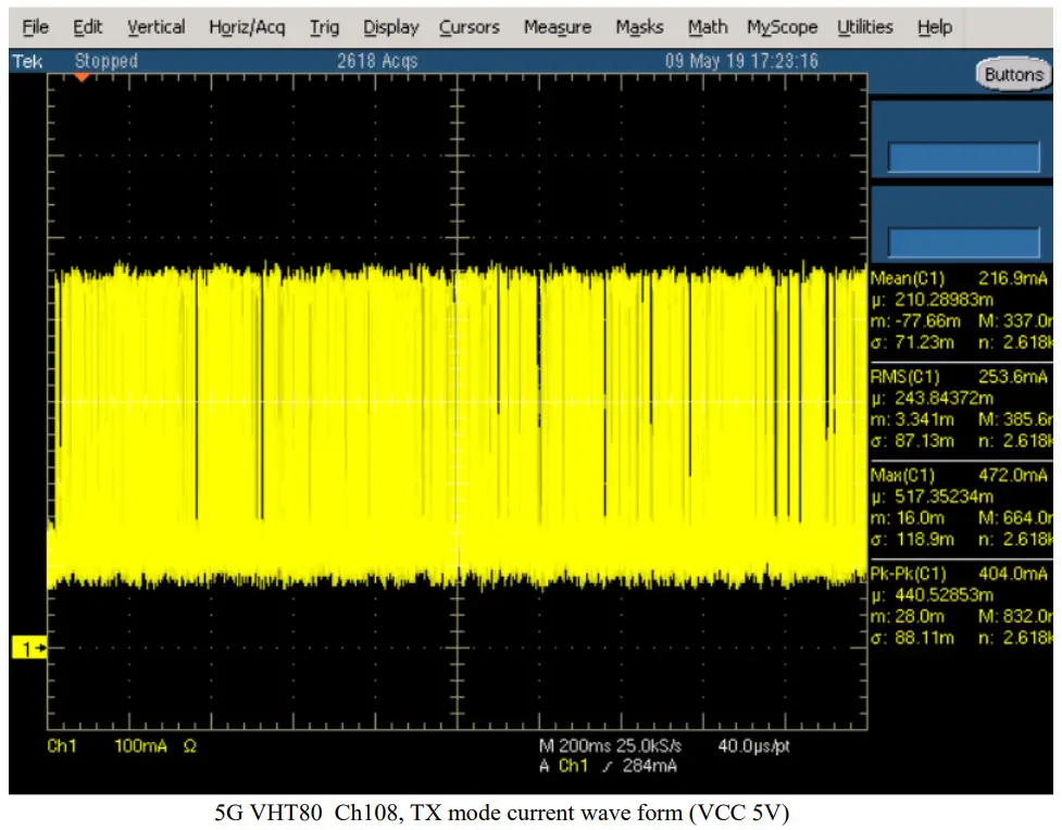
| Idle (5G, VHT80, Ch108) * | 115.8 | 444 |
| 5G, VHT80, Ch108, Rx mode | 226 | 468 |
| 5G, VHT80, Ch108, Tx mode | 253.6 | 472 |
| 5G, VHT80, Ch108, Rx mode + BT | 192.8 | 476 |
* Idle means, it is connected to access point but no data streaming.
4.3 Thermal characteristics
The operating temperature is 65 degrees. Tj max 125 degree for wifi/BT SOC.
RF Characteristic
5.1 Wi-Fi
Typical power levels for wi-fi radio are given in the figure below.
2.4G BAND | ||||
| Standard | 802.11b | 802.11g | 802.11n | 802.11n |
| Modulation | DSS,CCK | OFDM | OFDM | OFDM |
| Data Rate | 1,2,5.5,11 | 6,9,12,18,24,36,48,54 | MCS0 – 7 (HT20) | MCS0 – 7 (HT40) |
| Channel* | CH 1-13 | CH 1-13 | CH 1-13 | CH 1-13 |
| Power (dBm) | 13,5 | 13,5 | 13,5 | 13,5 |
5G BAND | ||||
| Standard | 802.11a | 802.11n/ac | 802.11n/ac | 802.11n/ac |
| Modulation | OFDM | OFDM | OFDM | OFDM |
| Data Rate | 6,9,12,18,24,36,48,54 | MCS0 – 9 (HT20) | MCS0 – 9 (HT40) | MCS0 – 9 (HT40) |
| Channel* | CH 36-64/ CH 100-165 | CH 36-64/ CH 100- 165 | CH 38-62/ CH 100- 159 | CH 42-58/ CH 100-155 |
| Power (dBm) | 14 | 14 | 14 | 14 |
*See country regulations
5.2 Bluetooth
Typical power levels for wi-fi radio are given in the figure below.
| Standard | Bluetooth 5.0 |
| Modulation | FHSS/ GFSK, pi/4‐DQPSK, 8DPSK |
| Data Rate | 1Mbps(GFSK),2Mbps(pi/4‐ DQPSK),3Mbps (8DPSK) |
| Channel | CH 0 ~ 78 |
| Power (dBm) | 4 dBm ~ 7dBm |
Antenna Characteristic
The module has onboard printed antennas with the given gain values below. It can support also an external antenna option with a UF.L micro coax RF socket (with BOM option). So, there are two possible configurations for the antennas. The first option is that use two onboard antennas, and the second option is one onboard antenna and one external antenna.
6.1 Onboard Printed Antenna Gains
| 2.4 Ghz | 5 Ghz low band (5180 to 5320 ) (ch 36-64) | 5 Ghz medium band (5500 to 5700) (ch100-140) | 5 Ghz high band (5745 to 5825) (ch149-165) | |
| Antenna 0 | 3,4 dBi | 2,97 dBi | 3,69 dBi | 2,89 dBi |
| Antenna 1 | 2,12 dBi | 3,7 dBi | 3,68 dBi | 2,83 dBi |
| BT | 0,29 dBi |
6.2 External Antenna Gains
Below two external antennas on the table may use as an option instead of the antenna 0.
| Antenna | 2.4 GHz | 5 GHz low band (5180 to 5320 ) (ch 36-64) | 5 GHz medium band (5500 to 5700) (ch100-140) | 5 GHz high band (5745 to 5825) (ch149-165) |
| JC-JCW601 | 3 dBi | 3 dBi | 3 dBi | 3 dBi |
| Taoglas_WS.01.B.305151 | 4,12 dBi | 4,74 dBi | Not available | Not available |
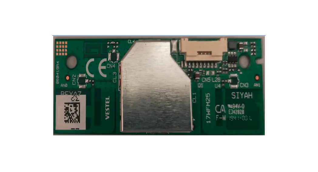
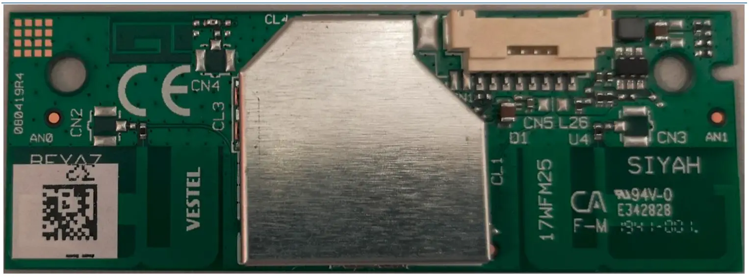
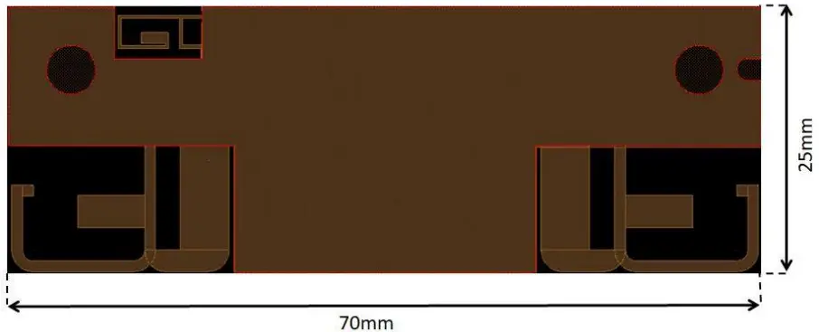
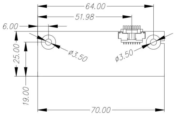
Mechanical Characteristics
Module dimension is 70×25 mm.
Pin Description
| Pin No. | Pin Name | I/O | Pin Description |
| 1 | WoBLE | I/O | Wake on Bluetooth Control Signal |
| 2 | WoWLAN | I/O | Wake on Wireless LAN Control Signal |
| 3 | GND | – | Ground |
| 4 | GND | – | Ground |
| 5 | USB_DP | I/O | USB Communication Signal |
| 6 | USB_DN | I/O | USB Communication Signal |
| 7 | VCC | I | VCC 5V |
| 8 | VCC | I | VCC 5V |
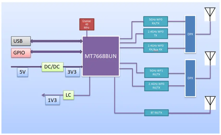
Block diagram
Environmental
10.1 Operating
Operating Temperature: 0 to 65 °C
Relative Humidity: 5-60% (non-condensing)
10.2 Storage
Temperature: -20 to 80 °C
Relevant Humidity: 5-85% (non-condensing)
Hardware & Software installation
11.1 Hardware Installation
The module is a built-in module. It will be used in-house production as an embedded device over a USB 2.0 interface and there is no need for any interaction with the end-user. Positioning of the module is defined by assembly operator instructions for each product by Vestel. The recommended installation of the module is shown below. The module should be mounted by considering the operating temperature. The temperature of the installation location should be between 0°C and 65 °C. The module can be installed in mobile or fixed hosts. For portable devices, a minimum separation distance of greater than “20cm” between the antenna and the human body shall be observed to avoid SAR requirements. The implementation of the module in a specific end-product should also be reviewed to ensure compliance with the FCC and IC requirements for SAR and MPE. The host integrator must follow the integration instructions provided by Vestel and ensure that the composite-system end product complies with the FCC requirements by a technical assessment or evaluation to the FCC rules and to KDB Publication 996369. The host label shows the FCC and ISED identifier of the module. FCC and ISED identifiers will be visible on the back cover of the host device. Also, the modular transmitter meets only FCC and ISED authorized for the specific rule parts, and the host must show complaints with his own rule parts. The module has been tested and approved as a Modular Radio in accordance with the appropriate FCC and IC standards. The supporting test data may be found in the modular test report. Since this module has been certified as a Modular Radio, this allows the end-user to integrate this module into an end-product without the requirement of re-certifying the radio module. The module-integrator is responsible for the unintentional conducted and radiated emissions and must verify that the integrated product is compliant with the rules associated with unintentional radiators. The module integrator is also required to maintain an engineering record of the verification testing and declare on the product through proper labeling and marking that the device is compliant with these particular rules. Although already certified, radio tests according to KDB996369 clause 3.4 have to be carried out also. External antennas can be installed if S3 (jumper) and CN2 (ufl connector) is placed on the board. S3 and S4 positions on the board are jumper options that obtain which antenna (S3 =onboard, S4 = external antenna) is used. Installed module’s FCC ID and IC numbers need to be clearly marked on the product with the following verbiage “Contains FCC ID: 2AVQS-17WFM25” and “Contains IC: 25888-17WFM25”. This device complies with part 15 of the FCC Rules. Operation is subject to the following two conditions: This device may not cause harmful interference, and this device must accept any interference received, including interference that may cause undesired operation. Changes or modifications not expressly approved by the party responsible for compliance could void the user’s authority to operate the equipment. Vestel provides user notices in both English and French when the product is made available for sale and/or lease in Canada. This device contains license-exempt transmitter(s)/receiver(s) that comply with Innovation, Science, and Economic Development Canada’s license-exempt RSS(s). Operation is subject to the following two conditions: 1. This device may not cause interference. 2. This device must accept any interference, including interference that may cause undesired operation of the device.
11.2 Software Installation
The SW driver is already installed to host the device software platform which is a Linux/Android OS. Proper country information must be selected from UI during first-time bootup settings. Country information is used to disable (deactivate) channels/frequency ranges which are not allowed by country regulations.
Country Regulations
The device is intended for home and office use in all countries and countries may have their own regulations to prohibit some WLAN frequencies. Proper country information must be selected from UI during first-time boot-up settings. Country information is used to disable (deactivate) channels/frequency ranges which are not allowed by country regulations. Below note on the use of devices in countries. For further information please refer to product IB or consult the country regulatory organization.
| Country | Restriction |
| Bulgaria | General authorization required for outdoor use and public service |
| France | In-door use only for 2454-2483.5 MHz |
| Italy | If used outside of own premises, general authorization is required |
| Greece | In-door use only for 5470 MHz to 5725 MHz band |
| Luxembourg | General authorization required for network and service supply (not for spectrum) |
| Norway | Radio transmission is prohibited for the geographical area within a radius of 20 km from the centre of Ny-Ålesund |
| Russian Federation | In-door use only |
| Israel | 5 GHz band only for 5180 MHz-5320 MHz range |
| Canada | In-door use only for 5150 MHz to 5250 MHz band |
| USA / Canada | In the 2.4GHz Band channel, 12 and 13 are disabled and for 802.11n (40) only CH 3-9 are enabled |
Basic transmitter specification is givens below figure;
| Frequency Ranges | Max Output Power (eirp) |
| 2400 – 2483,5 MHz (CH1-CH13) | < 100 mW |
| 5150 – 5250 MHz (CH36 – CH48) | < 200 mW |
| 5250 – 5350 MHz (CH52 – CH64) | < 200 mW |
| 5470 – 5850 MHz (CH100 – CH165) | < 200 mW |
Test modes
Test tools of Mediatek (QA tool) allow configuring test modes for different operational conditions.
Below steps should have been followed for testing Tx power on the module.
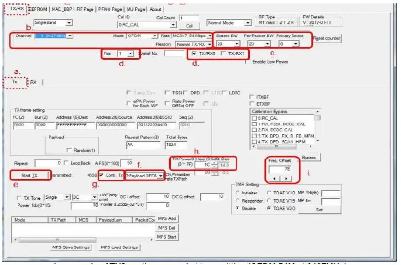
On TX/RX page:
a. Select TX sub-page as the following figure.
b. Set Channel/Mode/Rate.
c. Set BW. (Generally, System BW = Pre-Packet BW).
d. Select “Nss=1 or Nss=2” and choose “TX/RX0” or “TX/RX1′ to do transmitting.
e. Click’ and wait for a while then click “Stop Tx“. (Please repeat this step if the user change channel/BW/Rate)
f. Choose “Payload OFDM”.
g. Check “Conti. Tx” to start Tx 100% duty packet transmitting and uncheck “Conti. Tx” to stop.
h. Users can click the “![]() ” button to modify the power level of the transmitting signal after unchecking “Conti. Tx”.
” button to modify the power level of the transmitting signal after unchecking “Conti. Tx”.
i. Users can click the ![]() ” button to modify frequency offset of transmitting signal after unchecking “Conti. Tx”.
” button to modify frequency offset of transmitting signal after unchecking “Conti. Tx”.
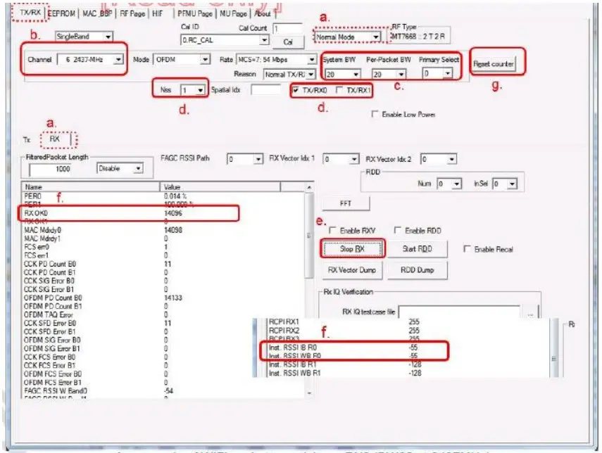
Below steps should have been followed for testing Rx on the module.
On TX/RX page
a. Select RX sub-page and “Normal Mode” as the following figure.
b. Set Channel frequency.
c. Set BW. (Generally, “Nss=1” System BW = Pre-Packet BW).
d. Select and choose “TX/RXO” to do receiving.
e. Click’START RX button to receive WIFI packets. Start RX Enable WIFI signal generator to transmit packets. Click the “STOP RX ” button to stop receiving. Stop RX
f. Successful received packets number would be shown at “RX OK” area and RSSI shown at “inst RSSI IB RO” area.
g. Users can click the “Reset counter” button to reset the counter value.