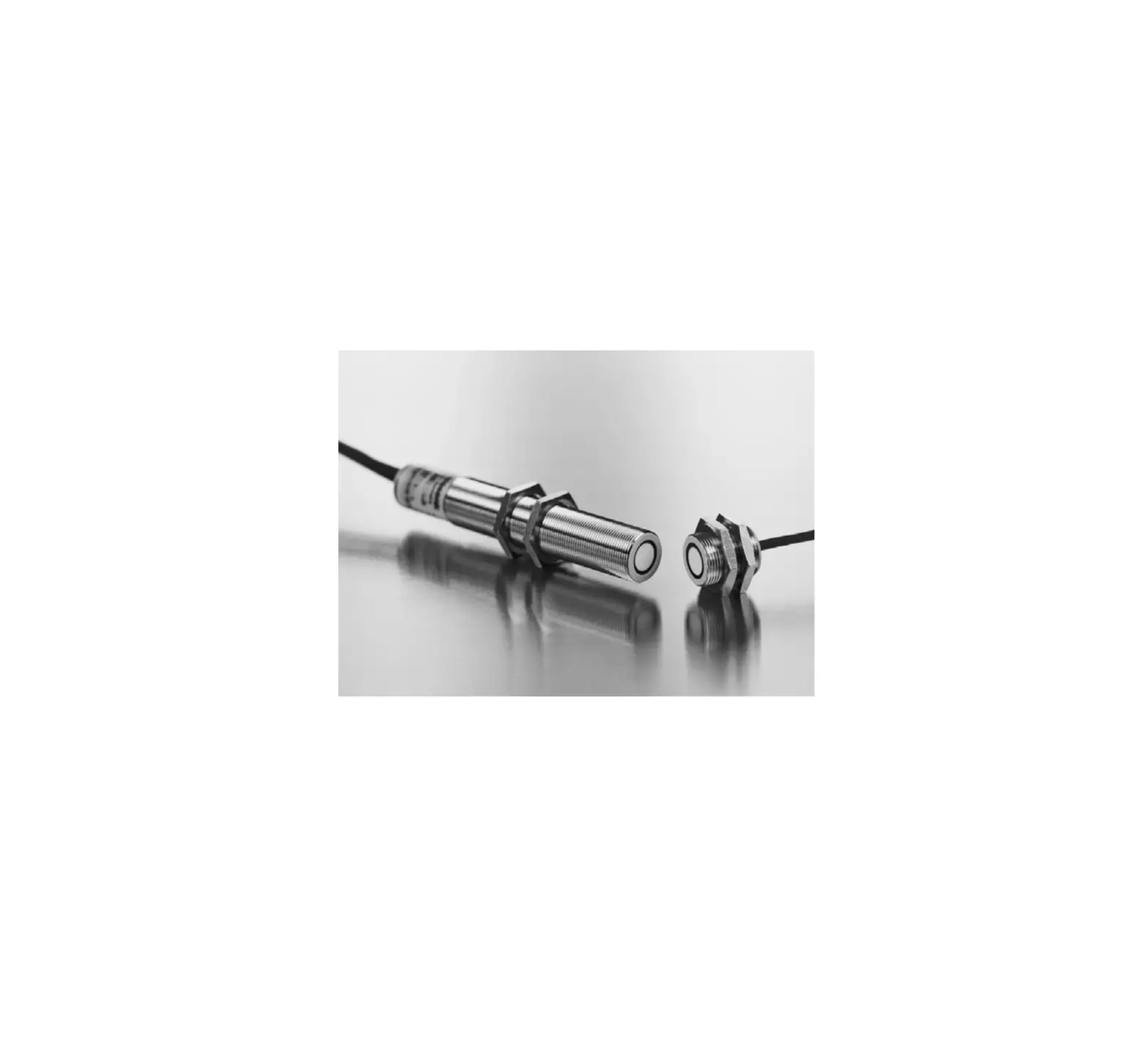
microsonic dbk-4-CD-O-M18 E+S Ultrasonic Double-Sheet Detection
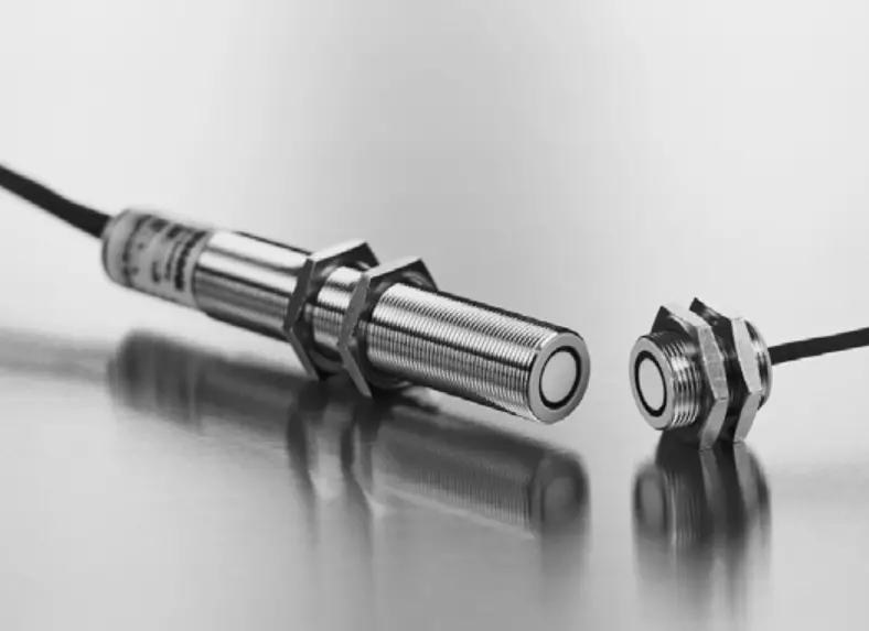
Ultrasonic double-sheet detection
dbk-4/CD/O/M18 E+S
dbk-4/CDD/O/M18 E+S
dbk-4/CEE/O/M18 E+S
dbk-4/BDD/O/M18 E+S
dbk-4/BEE/O/M18 E+S
Product Description
- No need for calibration to the sheet material or to the material weight (grammage)
- Grammages from 20 to 1,200 g/m2, films, thin sheet metals and fine corrugated can be scanned
- Can be mounted perpendicular to the passing sheet
- Special versions for use on sheet fed printing presses and for paper gatherers
- Time to respond to double or missing sheets from just 0.5 ms
- Double-sheet and missing-sheet output
- pnp and npn versions available
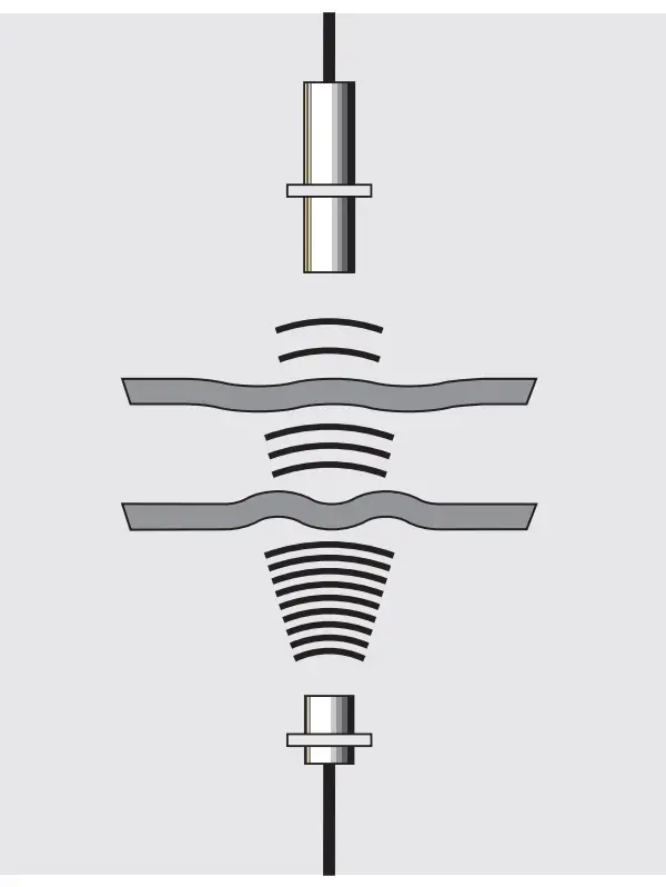
Operating principle
The purpose of the double-sheet detector is to detect two or more sheets that are lying one on top of the other. The sensor system consists of a transmitter and a receiver with integrated evaluation electronics.
An ultrahigh-frequency ultrasonic transmitter fires a sonic beam at the underside of the sheet. The beam causes the sheet to vibrate, which in turn causes a very small sound wave on the other side of the sheet. This sound wave is then evaluated by the ultrasonic receiver opposite. If there are two sheets one on top of the other („double sheet”), then the signal is weakened to such an extent that it hardly reaches the receiver.
The ultrasonic double-sheet detector is equipped with a control input that, depending on the particular model, is used to select different response times or to activate and deactivate the detector.
Fig. 1: Operating principle
The detector has two operating modes:
- Free Run-Mode
The ultrasonic double-sheet detector operates continuously. In the event of a double sheet or missing sheet, the corresponding output is set following the response time. When the error is cleared, the output is reset after the tripping delay. - Trigger-Mode
The ultrasonic double-sheet detector can be activated and deactivated by means of the control input. The control input is either level triggered or edge-triggered depending on the model of the detector. The response time in the event of a double or missing sheet is shortest immediately after activation, typically 0.5 ms. The control states in effect at the moment of deactivation are frozen until the next activation.
Important information for installation and application
When installing, starting up or carrying out maintenance work on the detection system, always perform all measures essential to ensuring the safety of staff and the system (cf. the instruction manual for the entire system and the instructions of the system operator). The double-sheet detectors of the dbk series have been designed for industrial applications.
The sensors are not items of safety equipment and must not be used for the purposes of personnel safety and machine protection!
Installation
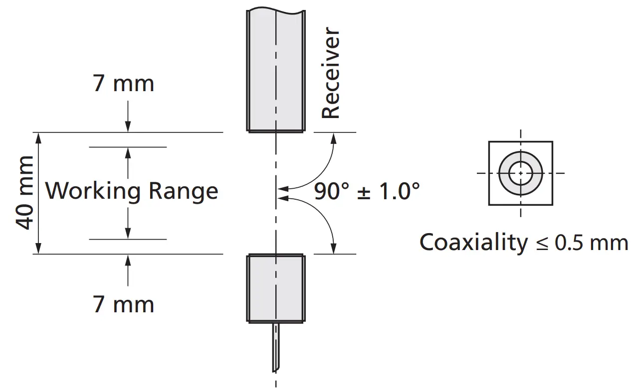
- Install the transmitter and receiver facing each other 40 mm ± 3 mm apart (see Fig. 3). Installation of the dbk is not dependent on the position.
Note!
- The distance between the transmitter/receiver and the passing sheet must never be less than 7 mm.
- The coaxiality must be ≤ 0.5 mm.
- Angular deviation between the transmitter and the receiver must be no more than 2°.
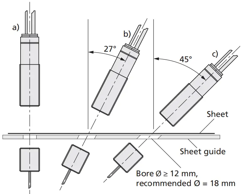
- When working with papers and thin films, we recommend you install the dbk perpendicular to the sheet (Fig. 4a).
- When working with thin sheet metals, thicker plastic films (e.g. credit cards), install the dbk with a deviation of 27° from the perpendicular (Fig. 4b).
- Types of paper that lead to false triggering when the dbk is mounted perpendicular (as a rule, types with air pockets) can frequently be scanned more accurately when the dbk is installed at an angle of 45° to the sheet. If the dbk is angled towards the corrugations of corrugated, the system can even be used to scan fine corrugateds (G and F; Fig. 4c).
- For other materials (such as wafer) a different position can be necessary. For these special materials please contact microsonic.
- The maximum tightening torque for the nuts is 15 Nm.
- If you install the transmitter in a recessed position or position a sheet guide between the transmitter and receiver, the hole must have a minimum diameter of ≥ 12 mm, but we recommend a diameter of 18 mm (Fig. 4).
→ Connect the transmitter to the receiver using the 2-pin plug-in connector.
Note!
- The cable between the transmitter and receiver must not be connected to an external voltage.
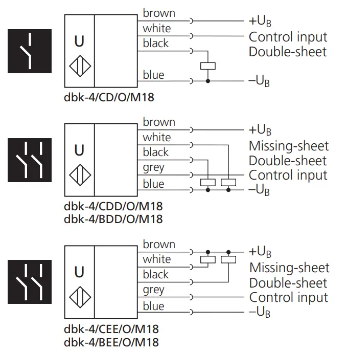
→ Connect the 4-core or 5-core control cable of the receiver as shown in Fig. 5.
Start-up
→ Switch on the power supply of the dbk. Check that the system is functioning properly with the aid of a test sheet.
→ Hold a test sheet inside the working range between the transmitter and receiver. The LED must light up green (if the LED lights up red, check the installation dimensions of the dbk and the test sheet you have chosen).
→ Hold a double test sheet (two sheets) inside the working range between the transmitter and receiver. The LED must light up red.
→ For double-sheet detectors with missing-sheet output:
Remove all sheets from between the transmitter and the receiver. The LED must flash red.
Note
The test sheet may be either a high grammage sheet of the material to be scanned or the test sheet available as an accessory from microsonic, which can be ordered under the article designation „dbk test sheet”. This test sheet serves as threshold material at room temperature and can be used to verify correct adjustment and operation of the dbk.
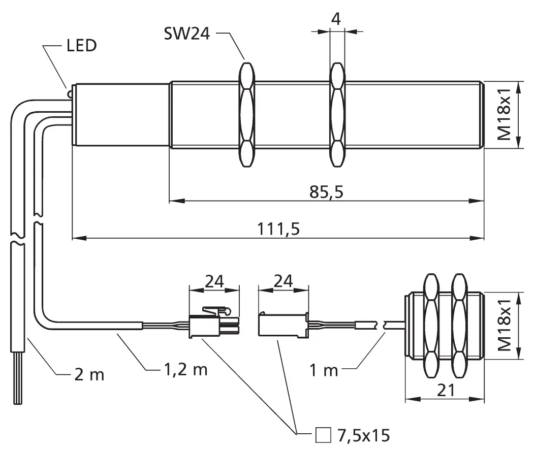
Dimensions, installation hints and terminal assignments
- Fig. 2: Dimensions

- Fig. 3: Installation and working range

- Fig. 4: Installation positions

- Fig. 5: Terminal assignments

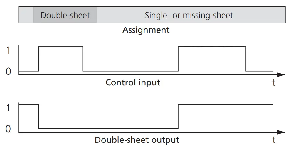
Time diagrams
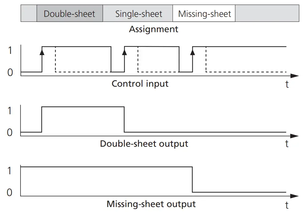
- Fig. 6: dbk-4/CD/O/M18 Trigger-Mode

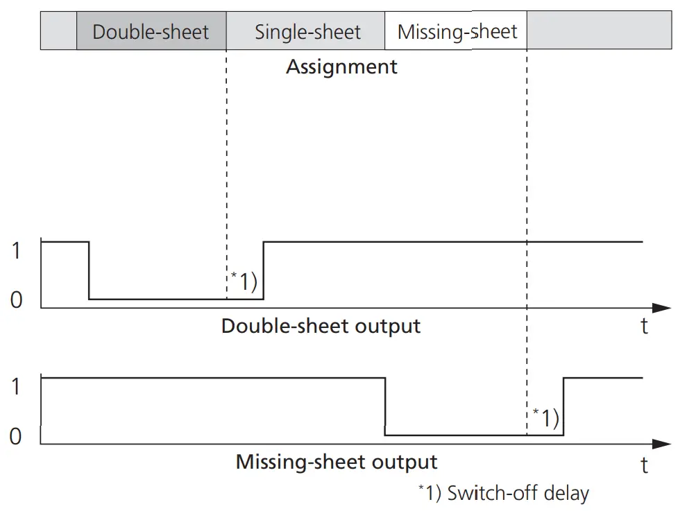
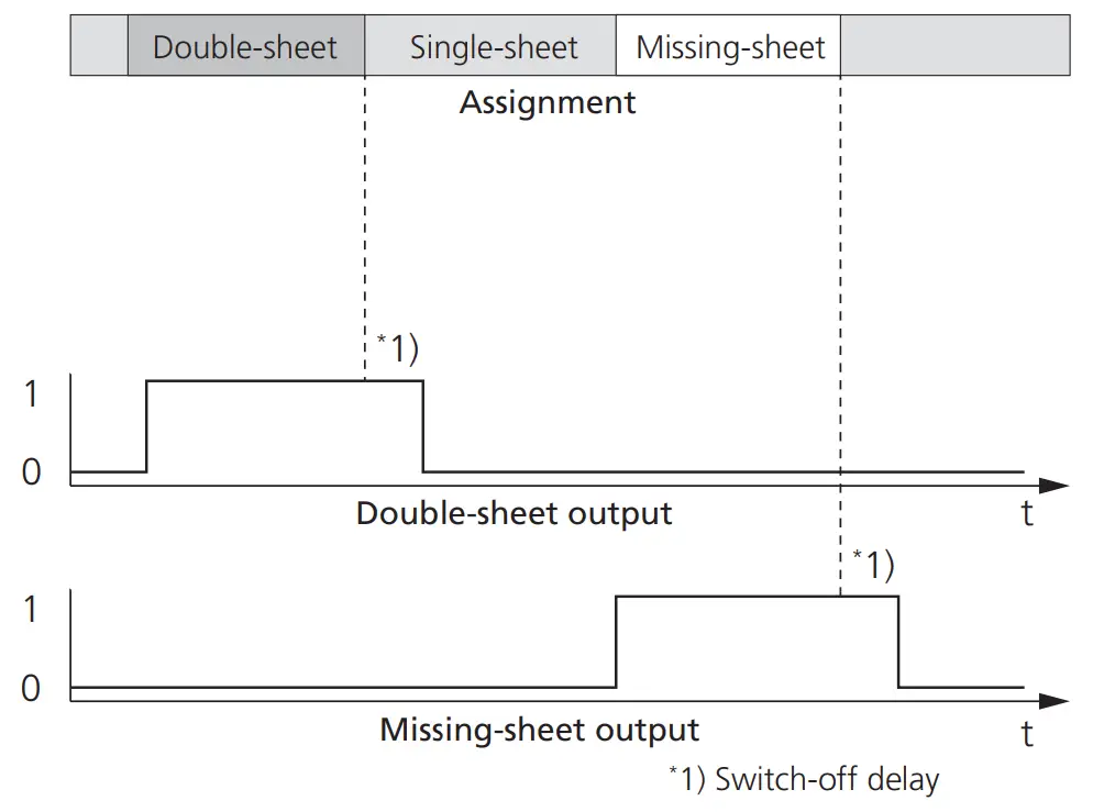
- Fig. 7: dbk-4/CD/O/M18 (Double-sheet output) and dbk-4/CDD/S/M18 Free-Run-Mode

- Fig. 8: dbk-4/CEE/O/M18 Free-Run-Mode

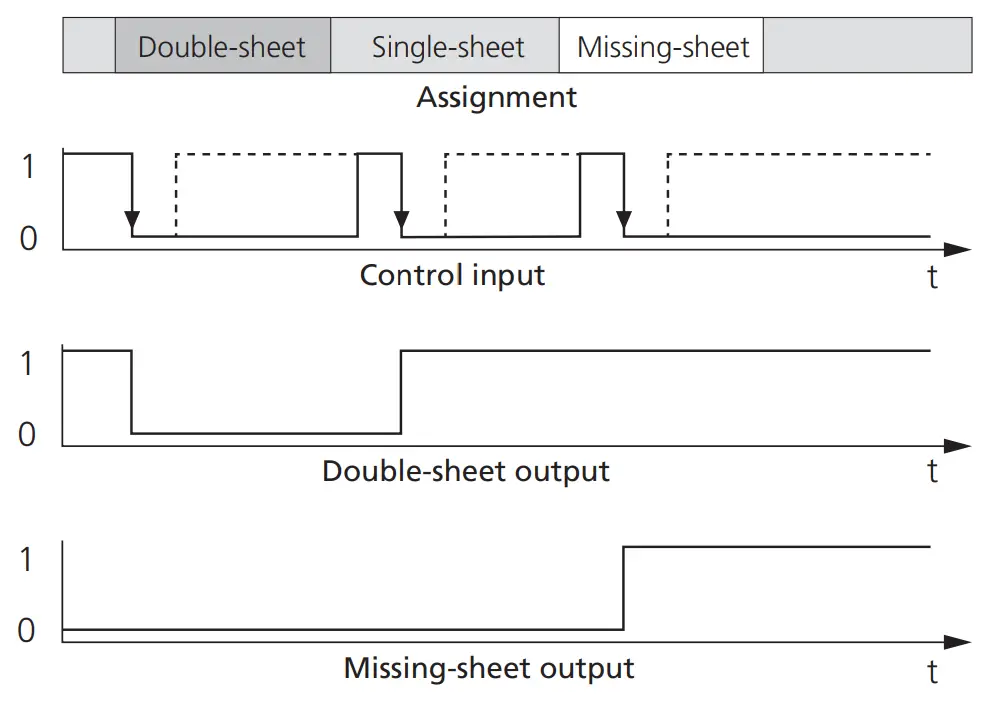
- Fig. 9: dbk-4/BDD/O/M18 Trigger-Mode

- Fig. 10: dbk-4/BEE/O/M18 Trigger-Mode
Technical Data | |||||
| model name | dbk-4/CD/O/M18 E+S | dbk-4/CDD/O/M18 E+S | dbk-4/CEE/O/M18 E+S | dbk-4/BDD/O/M18 E+S | dbk-4/BEE/O/M18 E+S |
| transmitter-receiver spacing | 40 mm ±3 mm | 40 mm ±3 mm | 40 mm ±3 mm | 40 mm ±3 mm | 40 mm ±3 mm |
| transmitter-receiver blind zone | 7 mm in front of both transmitter and receiver | 7 mm in front of both transmitter and receiver | 7 mm in front of both transmitter and receiver | 7 mm in front of both transmitter and receiver | 7 mm in front of both transmitter and receiver |
| permissible angular deviation | ±45° from the perpendicular to the sheet | ±45° from the perpendicular to the sheet | ±45° from the perpendicular to the sheet | ±45° from the perpendicular to the sheet | ±45° from the perpendicular to the sheet |
| ultrasonic frequency | 400 kHz | 400 kHz | 400 kHz | 400 kHz | 400 kHz |
| resolution | 2 sheets not stuck together across entire surface | 2 sheets not stuck together across entire surface | 2 sheets not stuck together across entire surface | 2 sheets not stuck together across entire surface | 2 sheets not stuck together across entire surface |
| working range | papers with grammages of 20 to 1,200 g/m2, metal-laminated sheets and films up to 0.4 mm thick, self-adhesive films, sheet metals up to 0.3 mm thick, fine corrugateds | papers with grammages of 20 to 1,200 g/m2, metal-laminated sheets and films up to 0.4 mm thick, self-adhesive films, sheet metals up to 0.3 mm thick, fine corrugateds | papers with grammages of 20 to 1,200 g/m2, metal-laminated sheets and films up to 0.4 mm thick, self-adhesive films, sheet metals up to 0.3 mm thick, fine corrugateds | papers with grammages of 20 to 1,200 g/m2, metal-laminated sheets and films up to 0.4 mm thick, self-adhesive films, sheet metals up to 0.3 mm thick, fine corrugateds | papers with grammages of 20 to 1,200 g/m2, metal-laminated sheets and films up to 0.4 mm thick, self-adhesive films, sheet metals up to 0.3 mm thick, fine corrugateds |
| operating voltage UB | 20 to 30 V DC | 20 to 30 V DC | 20 to 30 V DC | 20 to 30 V DC | 20 to 30 V DC |
| residual ripple | ±10 % | ±10 % | ±10 % | ±10 % | ±10 % |
| no-load current consumption | £35 mA | £35 mA | £35 mA | £35 mA | £35 mA |
| type of connection | 4-core cable, 2,000 mm long | 5-core cable, 2,000 mm long | 5-core cable, 2,000 mm long | 5-core cable, 2,000 mm long | 5-core cable, 2,000 mm long |
| signal cable | on receiver: 1,200 mm on transmitter: 1,000 mm, with 2-pin plug-in connector, IP 20 | on receiver: 1,200 mm on transmitter: 1,000 mm, with 2-pin plug-in connector, IP 20 | on receiver: 1,200 mm on transmitter: 1,000 mm, with 2-pin plug-in connector, IP 20 | on receiver: 1,200 mm on transmitter: 1,000 mm, with 2-pin plug-in connector, IP 20 | on receiver: 1,200 mm on transmitter: 1,000 mm, with 2-pin plug-in connector, IP 20 |
| terminal assignment | |||||
| brown | +UB | +UB | +UB | +UB | +UB |
| blue | –UB (0 V) | –UB (0 V) | –UB (0 V) | –UB (0 V) | –UB (0 V) |
| white | control input | missing sheet | missing sheet | missing sheet | missing sheet |
| black | double sheet | double sheet | double sheet | double sheet | double sheet |
| grey | – | control input | control input | control input | control input |
| controls | none required | none required | none required | none required | none required |
| programmable | none required | none required | none required | none required | none required |
| double-sheet output | pnp, +UB–2 V, Imax = 500 mA, short-circuit-proof, NC contact | pnp, +UB–2 V, Imax = 500 mA, short-circuit-proof, NC contact | npn, –UB+2 V, Imax = 500 mA, short-circuit-proof, NC contact | pnp, +UB–2 V, Imax = 500 mA, short-circuit-proof, NO contact | npn, –UB+2 V, Imax = 500 mA, short-circuit-proof, NO contact |
| missing-sheet output | – | pnp, +UB–2 V, Imax = 500 mA, short-circuit-proof, NC contact | npn, –UB+2 V, Imax = 500 mA, short-circuit-proof, NC contact | pnp, +UB–2 V, Imax = 500 mA, short-circuit-proof, NC contact | npn, –UB+2 V, Imax = 500 mA, short-circuit-proof, NC contact |
| response time, Trigger Mode | 4.5 ms | – | – | 0.5 ms | 0.5 ms |
| response time, Free Run Mode | 24.5 ms | 2.5 ms or 6.5 ms | 2.5 ms or 6.5 ms | – | – |
| tripping delay, Trigger Mode | 40 ms or state frozen until next enable | – | – | State frozen until next edge | State frozen until next edge |
| tripping delay, Free Run Mode | 160 ms | 10 ms | 10 ms | – | – |
| indicator | green: stand-by red: double sheet | green: stand-by red: double sheet flashing red: missing sheet | green: stand-by red: double sheet flashing red: missing sheet | green: stand-by red: double sheet flashing red: missing sheet | green: stand-by red: double sheet flashing red: missing sheet |
| UE at control input | dbk deactivated: UE < 0.1 x UB or UE > 0.9 x UB dbk activated: 0.3 x UB < UE < 0.7 x UB (IE £ 100µA or control input open) (low side or high side triggerable) | response time 6.5 ms: UE > 9 V DC response time 2.5 ms: UE < 5 V DC or control input open | response time 6.5 ms: UE > 9 V DC response time 2.5 ms: UE < 5 V DC or control input open | dbk activated for one scan: edge change from –UB to +UB; edge width ³1 ms | dbk activated for one scan: edge change from +UB to –UB; edge width ³1 ms |
| description of control input | If the control input is pulled to +UB or –UB (high- or low-active input), the dbk is deactivated; the state of the switched output before deactivation is frozen. If the control input is released, the dbk starts its scans with a response time of 4.5 ms (Trigger Mode). If the dbk is not deactivated again, it continues scanning continuously (Free Run Mode) with a response time of 6.5 ms. After 500 ms, the response time in Free Run Mode is extended to 24.5 ms and remains at this value. | Free Run Mode only: The dbk scans continuously. If the control input remains open-circuited or if it is applied to –UB, the response time is 2.5 ms. If the control input is applied to +UB, the response time is 6.5 ms. | Free Run Mode only: The dbk scans continuously. If the control input re- mains open-circuited or if it is applied to –UB, the response time is 2.5 ms. If the control input is applied to +UB, the response time is 6.5 ms. | Trigger Mode only: one scan is performed with a rising edge at the con- trol input (edge change from –UB to +UB). After the response time of 0.5 ms, both outputs are set in accordance with the result of the scan. The states of the two switching outputs are frozen until the next rising edge. | Trigger Mode only: one scan is performed with a rising edge at the con- trol input (edge change from +UB to –UB). After the response time of 0.5 ms, both outputs are set in accordance with the result of the scan. The states of the two switching outputs are frozen until the next falling edge. |
| housing | nickel-plated brass sleeve plastic parts: PBT cable: PVC sheath ultrasonic transducer: polyurethane foam, epoxy resin with glass content | nickel-plated brass sleeve plastic parts: PBT cable: PVC sheath ultrasonic transducer: polyurethane foam, epoxy resin with glass content | nickel-plated brass sleeve plastic parts: PBT cable: PVC sheath ultrasonic transducer: polyurethane foam, epoxy resin with glass content | nickel-plated brass sleeve plastic parts: PBT cable: PVC sheath ultrasonic transducer: polyurethane foam, epoxy resin with glass content | nickel-plated brass sleeve plastic parts: PBT cable: PVC sheath ultrasonic transducer: polyurethane foam, epoxy resin with glass content |
| max. tightening torque of nuts | 15 Nm | 15 Nm | 15 Nm | 15 Nm | 15 Nm |
| degree of protection per EN 60529 | IP 65 | IP 65 | IP 65 | IP 65 | IP 65 |
| operating temperature | +5 to +60 °C | +5 to +60 °C | +5 to +60 °C | +5 to +60 °C | +5 to +60 °C |
| storage temperature | –40 to +85 °C | –40 to +85 °C | –40 to +85 °C | –40 to +85 °C | –40 to +85 °C |
| weight | 267 g | 277 g | 277 g | 277 g | 277 g |
| standard conformed with | EN 60947-5-2 | EN 60947-5-2 | EN 60947-5-2 | EN 60947-5-2 | EN 60947-5-2 |
Customer Support
![]()
microsonic GmbH / Phoenixseestraße 7 / 44263 Dortmund / Germany / T +49 231 975151-0 / F +49 231 975151-51 / E [email protected] / W microsonic.de
The content of this document is subject to technical changes. Specifications in this document are presented in a descriptive way only. They do not warrant any product features.