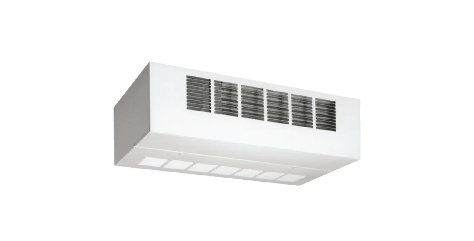
AE-Air ACHBC Chilled or Hot Water Fan Coil Cabinet
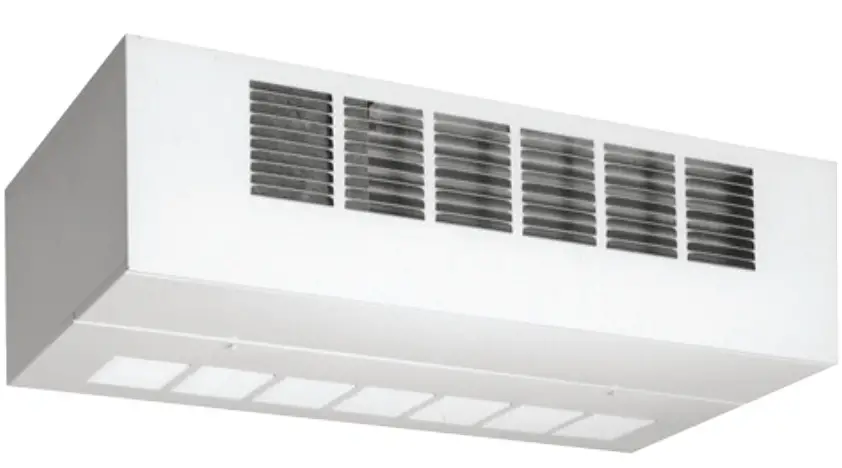
Features
- Attractive baked on finish
- Removable side panels for easier valve installation
- Easy access throwaway filter
- Copper tube coils
- Hinged access panel
- Manual air vents
- Insulated condensate drain pan
- 2 and 4-pipe models available
- 120V motor (3-speed)
- 277V option available
- 220V, 50Hz models available
FEATURES / BENEFITS
- Basic Unit
All fan coils are manufactured with heavy gauge galvanized steel to resist corrosion. All models are approved for installation with “0” clearance to combustible material. - Insulation
Plenums and cabinets are insulated with Tuf-Skin dual density fiber glass blanket insulation with an antimicrobial agent. - Ceiling Panels
Hinged access/return panels are manufactured with heavy gauge galvanized steel with captive mounting screws and an attractive white baked powder finish. - Condensate Pans
Positive sloped drain pans are galvanized steel, coated on the inside surface with insulation. Pan includes both primary and secondary drain connections. - Return Air Plenums
Return air plenums are manufactured from galvanized steel insulated with dual density fiber glass blanket insulation and a 1” TA fiber glass filter. - Coils
Constructed with seamless copper tubes and headers. The tubes are mechanically expanded into corrugated aluminum fin material for a permanent primary to secondary surface bond. Coils are tested under water at 450 PSI for operation at 300 PSI. Coils include manual air vents. - Fan Wheels-Housing
The fan wheels are double width, double inlet (DWDI) forward curved, centrifugal type. Wheels are statically and dynamically balanced for smooth, quite operation. The housing is constructed from heavy gauge galvanized steel with die-formed inlet cones. - Motors
Standard motors are PSC, permanently lubricated type with internal thermal overload protection. - Options
Factory mounted options include ECM motors stainless steel drain pans, foil faced cabinet insulation, Multi-24 3-speed 24V control, valve packages, thermostats, aqua stats, service switches. 120V, 208V/230V, 277V, 60hz
MODEL NOMENCLATUR
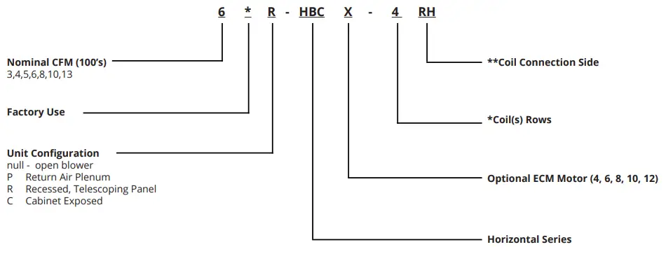
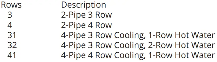
Coil Configurations
Coil Connection Side
- RH Right Hand (default)
- LH Left Hand
- Hand connection is determined by looking with airflow
Available Voltage (PSC Motors)
- 120V/1/60
- 208-230V/1/60
- 277V/1/60
Available Voltage (ECM Motors)
- 120V/1/60
- 277V/1/60
In keeping with its policy of continuous progress and product improvement, AE-Air reserves the right to make changes without notice. Maintenance for all AE-Air products is available under “Product Maintenance” at www.AE-Air.com.
DIMENSION
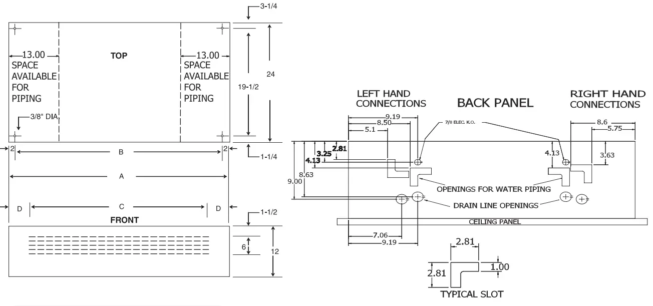
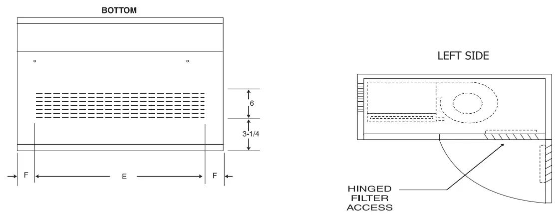
| MODEL | A | B | C | D | E | F | FILTER SIZE (INCL) | CONNECTIONS PRIMARY O.D. |
| 3*ACHBC | 38 | 34 | 26 | 6 | 31-1/2 | 3-1/2 | 10 X 37 |
5/8” |
| 4*ACHBC | 44 | 40 | 31-1/2 | 6 | 37 | 3-1/2 | 10 X 43 | |
| 5*ACHBC | 48 | 44 | 37 | 5-1/2 | 42-1/2 | 3 | 10 X 46 | |
| 6*ACHBC | 48 | 44 | 37 | 5-1/2 | 42-1/2 | 3 | 10 X 46 | |
| 8*ACHBC | 54 | 50 | 42-1/2 | 6 | 48 | 3 | 10 X 53 | |
| 10*ACHBC | 60 | 56 | 48 | 6 | 53 | 3-1/2 | 10 X 59 | |
| 12*ACHBC | 67 | 63 | 53 | 7 | 58-1/2 | 4 | 10 X 65 | |
| 13*ACHBC | 67 | 63 | 53 | 7 | 58-1/2 | 4 | 10 X 65 |
NOTES:
- ALL DIMENSIONS IN INCHES.
- COIL CONNECTION TOLERANCE ± 1/4”.
- LEFT HAND UNIT SHOWN, RIGHT HAND MIRROR IMAGE. (HAND IS DETERMINED BY FACING THE BLOWER END)
- Side panels are removable for easier valve access.
CHBC (ALL) PSC BLOWER PERFORMANCE
| PSC MOTOR | ACHBC (120 Volt) | ACHBC (277 Volt) | ||||||||||
| (3 ROW 120 Volt) | (3 ROW 277 Volt) | |||||||||||
| MODEL | HP | MAX RPM | AMPS (120V) | FAN SPEED | CFM | MODEL | HP | MAX RPM | AMPS (120V) | FAN SPEED | CFM | |
| 3*ACHBC-3 | 1/20 | 1050 | .09 | HI MED LOW | 300 245 210 | 3*ACHBC-3 | 1/20 | 1100 | 0.48 | HI MED LOW | 285 220 160 | |
| 4*ACHBC-3 | 1/12 | 1050 | 1.1 | HI MED LOW | 480 375 325 | 4*ACHBC-3 | 1/15 | 105 | 0.52 | HI MED LOW | 450 365 315 | |
| 5*ACHBC-3 | 1/12 | 1050 | 1.3 | HI MED LOW | 560 465 345 | 5*ACHBC-3 | 1/15 | 1050 | 0.52 | HI MED LOW | 535 375 305 | |
| 6*ACHBC-3 | 1/8 | 1550 | 1.9 | HI MED LOW | 730 650 550 | 6*ACHBC-3 | 1/12 | 1625 | 0.56 | HI MED LOW | 670 545 455 | |
| 8*ACHBC-3 | 1/5 | 1550 | 3.0 | HI MED LOW | 920 750 605 | 8*ACHBC-3 | 1/6 | 1550 | 0.80 | HI MED LOW | 880 700 585 | |
| 10*ACHBC-3 | 1/4 | 1550 | 3.6 | HI MED LOW | 1145 930 795 | 10*ACHBC-3 | 1/4 | 1625 | 1.26 | HI MED LOW | 1140 920 755 | |
| 13*ACHBC-3 | 1/5 (two) | 1550 | 2.3 Ea. | HI MED LOW | 1500 1320 1160 | 13*ACHBC-3 | 1/6 (two) | 1550 | 0.80 Ea. | HI MED LOW | 1535 1340 1140 | |
| (4 ROW or 3/1 Split 120 Volt) | (4 ROW or 3/1 Split 277 Volt) | |||||||||||
| 3*ACHBC-4 -31 | 1/20 | 1050 | 0.9 | HI MED LOW | 280 230 195 | 3*ACHBC-4 -31 | 1/20 | 1100 | 0.48 | HI MED LOW | 270 215 175 | |
| 4*ACHBC-4 -31 | 1/12 | 1050 | 1.1 | HI MED LOW | 450 370 320 | 4*ACHBC-4 -31 | 1/15 | 1050 | 0.52 | HI MED LOW | 435 355 315 | |
| 5*ACHBC-4 -31 | 1/12 | 1050 | 1.3 | HI MED LOW | 550 455 340 | 5*ACHBC-4 -31 | 1/15 | 1050 | 0.52 | HI MED LOW | 525 360 300 | |
| 6*ACHBC-4 -31 | 1/8 | 1550 | 1.9 | HI MED LOW | 710 615 535 | 6*ACHBC-4 -31 | 1/12 | 1625 | 0.56 | HI MED LOW | 665 540 445 | |
| 8*ACHBC-4 -31 | 1/5 | 1550 | 3.0 | HI MED LOW | 885 730 595 | 8*ACHBC-4 -31 | 1/6 | 1550 | 0.80 | HI MED LOW | 835 680 555 | |
| 10*ACHBC-4 -31 | 1/4 | 1550 | 3.6 | HI MED LOW | 1110 915 770 | 10*ACHBC-4 -31 | 1/4 | 1625 | 1.26 | HI MED LOW | 1100 890 745 | |
| 13*ACHBC-4 -31 | 1/5 (two) | 1550 | 2.3 Ea. | HI MED LOW | 1450 1270 1130 | 13*ACHBC-4 -31 | 1/56 (two) | 1550 | 0.80 Ea. | HI MED LOW | 1465 1280 1110 | |
| (4/1 or 3/2 Split 120 Volt) | (4/1 or 3/2 Split 277 Volt) | |||||||||||
| 3*ACHBC-41 -32 | 1/20 | 1050 | 0.9 | HI MED LOW | 270 225 190 | 3*ACHBC-41 -32 | 1/20 | 1100 | 0.48 | HI MED LOW | 265 210 160 | |
| 4*ACHBC-41 -32 | 1/12 | 1050 | 1.1 | HI MED LOW | 420 355 305 | 4*ACHBC-41 -32 | 1/15 | 1050 | 0.52 | HI MED LOW | 440 355 315 | |
| 5*ACHBC-41 -32 | 1/12 | 1050 | 1.3 | HI MED LOW | 520 440 325 | 5*ACHBC-41 -32 | 1/15 | 1050 | 0.52 | HI MED LOW | 480 350 285 | |
| 6*ACHBC-41 -32 | 1/8 | 1550 | 1.9 | HI MED LOW | 625 520 440 | 6*ACHBC-41 -32 | 1/12 | 1625 | 0.56 | HI MED LOW | 630 510 430 | |
| 8*ACHBC-41 -32 | 1/5 | 1550 | 3.0 | HI MED LOW | 875 725 615 | 8*ACHBC-41 -32 | 1/6 | 1550 | 0.80 | HI MED LOW | 830 660 550 | |
| 10*ACHBC-41 -32 | 1/4 | 1550 | 3.6 | HI MED LOW | 1075 900 765 | 10*ACHBC-41 -32 | 1/4 | 1625 | 1.26 | HI MED LOW | 1065 905 750 | |
| 13*ACHBC-41 -32 | 1/5 (two) | 1550 | 2.3 Ea. | HI MED LOW | 1420 1315 1160 | 13*ACHBC-41 -32 | 1/6 (two) | 1550 | 0.80 Ea. | HI MED LOW | 1415 1245 1090 | |
GUIDE SPECIFICATIONS
General
- SECTION INCLUDES
Fan Coil Units - REFERENCES
- AMCA 99 – Standards Handbook
- AMCA 210 — Laboratory Methods for Testing Fans for Rating Purposes
- AMCA 300 – Test Code for Sound Rating Air Moving Devices
- ARI 440 – Room Fan-Coil Unit
- ASTMB117 – Standard Practice for Operating Salt Spray Apparatus
- NEMA MGI – Motors and Generators
- NFPA 70 – National Electric Code
- SMACNA – HVAC Duct Construction Standards – Metal and Flexible
- UL 723 – Test for Surface Burning Characteristics of Building Materials
- UL 900 – Test Performance of Air Filter Units
- UL 1995 – Standard for Heating and Cooling Equipment
- UL 94 – Test for Flammability of Plastic Materials for Parts in Devices and Appliances
- SUBMITTALS
- Shop drawings: Indicate assembly, unit dimensions, weight loading, required clearances, construction details, field connection details, and electrical characteristics and connection requirements. A computer generated capacity selection shall be submitted for each cooling coil with design points and final operating point clearly noted.
- Product Data:
- Provide literature that indicates dimensions, weights, capacities, ratings, fan performance, finishes of materials, and electrical characteristics and connection requirements.
- Provide data of filter media, filter performance data.
- Manufacturer’s installation instructions.
- OPERATION AND MAINTENANCE DATA
Maintenance Data: Include instructions for lubrication, filter replacement and motor and drive replacement. - QUALIFICATIONS
Maintenance Data: Include instructions for lubrication, filter replacement and motor and drive replacement. - DELIVERY, STORAGE, AND HANDLING
- Accept products on site on factory-installed shipping skids. Inspect for damage.
- Store in clean dry place and protect from weather and construction traffic. Handle carefully to avoid damage to components, enclosures, and finish.
- ENVIRONMENTAL REQUIREMENTS
Do not operate units for any purpose, temporary or permanent, until ductwork is clean, filters are in place, and fan has been test run under observation.
Products
- MANUFACTURERS
- The following manufacturers are approved for use. No substitutions will be permitted.
- First Company, Dallas TX
- CASING
- Unit shall have corrosion resistant casing consisting of galvanized steel panels. Unit panels shall be fully insulated with 1.5lb fiberglass insulation with anti-microbial agent. Removable panels shall provide full access to unit components..
- Drain pans shall be heavy gauge galvanized steel with an insulating coating. Optional stainless steel drain pan shall include an insulating coating. Drain pans shall be removable for cleaning or replacement without removing coils or disturbing coil connections.
- SUPPLY FAN
- Provide DWDI forward-curved supply fans. Fan assemblies shall be statically and dynamically balanced by manufacturer. The housings are constructed from heavy gauge galvanized steel with die-formed inlet cones.
- Fan and motor mounting platform shall be a minimum of 12 gauge LFQ galvanized steel.
- MOTORS
Direct drive motors to be PSC or ECM type, permanently lubricated type with internal thermal overload protection and mounted with rubber isolation bushings. - ELECTRICAL
Provide units with 115, 208-230, or 277V, 3-speed with 24v control transformer, and 15 amp service switch or optional ECM motor with 120/24V control transformer, 15 amp service switch, 4 speed taps. Controls to be factory mounted and tested. - COOLING AND HEATING COIL SECTIONS
- Provide access to coils for service and cleaning..
- Water Coils: fins shall have full drawn collars to provide a continuous surface cover over the entire tube for maximum heat transfer. Tubes shall be mechanically expanded into the fins to provide a continuous primary-tosecondary compression bond over the entire finned length for maximum heat transfer rates. Bare copper tube shall not be visible between fins. Coil tubes shall be seamless copper, expanded into fins, and brazed at joints. Coil connections shall be copper with sweat connection size to be determined by manufacturer based upon the most efficient coil circuiting. Manual air vent connections shall be provided at the highest point to assure proper venting. Coils shall be tested with 350 pounds air pressure and suitable for 300 psig working pressure. Coil casings shall be a formed channel frame of galvanized steel.
- FILTERS
Filter to be disposable type and media shall be UL 900 listed, Class I or Class II.
Execution
- INSTALLATION
Install in accordance with manufacturer’s instructions
ACCESS PANELS /FILTER
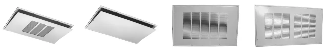
| *STANDARD PANEL OPTIONS FOR HBC SERIES | *IAQ MERV 8 PANEL OPTIONS FOR HBC SERIES | ||||||||
| PART # | UNIT SIZE | PANEL TYPE | FRAME DIMENSIONS | *FILTER SIZE | PART # | UNIT SIZE | PANEL TYPE | FRAME DIMENSIONS | *FILTER SIZE |
| 965 | 3,4,5,6 | LOUVERED | 27-1/2 X 43 | 20X20X1 (1) | 965-M8 | 3,4,5,6 | LOUVERED | 27-1/2 X 43 | 20X30X1 (1) |
| 965-1 | SOLID | ||||||||
| 966 | 8 | LOUVERED | 27-1/2 X 49 | 20X20X1 (1) | 966-M8 | 8 | LOUVERED | 27-1/2 X 49 | 20X20X1 (2) |
| 966-1 | SOLID | ||||||||
| 967 | 10 | LOUVERED | 27-1/2 X 55-1/2 | 20X20X1 (1) | 967-M8 | 10 | LOUVERED | 27-1/2 X 55-1/2 | 20X20X1 (2) |
| 967-1 | SOLID | ||||||||
| 967-4 | 12/13 | LOUVERED | 27-5/8 X 70-1/8 | 10X65X1 (1) | 967-8M8 | 12/13 | LOUVERED | 27-5/8 X 70-1/8 | 20X30X1 (2) |
| 967-5 | SOLID | ||||||||
NOTE: * Filters not included
| IAQ PANEL PERFORMANCE DATA (4) (Clean Filter) | ||||||||||
| CFM | ||||||||||
| 500 | 600 | 700 | 800 | 900 | 1000 | 1100 | 1200 | 1300 | 1500 | |
| 965-M8 with AF20301HV (20×030, Merv 8) Filters (2) | 0.04 | 0.06 | 0.06 | 0.08 | 0.09 | 0.10 | – – – | – – – | – – – | – – – |
| 966-M8 with AF20201HV (20×020, Merv 8) Filters (2) | 0.04 | 0.06 | 0.06 | 0.08 | 0.09 | 0.10 | – – – | – – – | – – – | – – – |
| 967-M8 with AF20201HV (20×020, Merv 8) Filters (2) | – – – | 0.05 | 0.05 | 0.07 | 0.08 | 0.10 | – – – | – – – | – – – | – – – |
| 967-6-M8 with AF20251HV (20×025, Merv 8) Filters (2) | – – – | – – – | – – – | 0.05 | 0.06 | 0.07 | 0.08 | 0.09 | – – – | – – – |
| 967-8-M8 with AF20301HV (20×30, Merv 8) Filters (2) | – – – | – – – | – – – | – – – | – – – | 0.06 | 0.06 | 0.08 | 0.08 | 0.10 |
NOTES:
- The above is the actual laboratory test data or these panels.
- Glassfloss® Industries HV series Merv 8 filters were used to generate above data (filters must be field supplied)
- Alternate Merv 8 filters would be acceptable provided they have equal or less resistance.
- Refer to fan coil specification sheets for fan coil blower data.
ACCESSORIES
THERMOSTATS
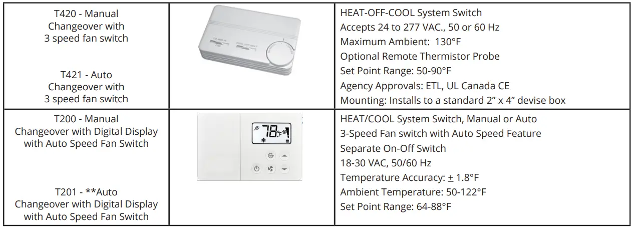
SINGLE SPEED THERMOSTATS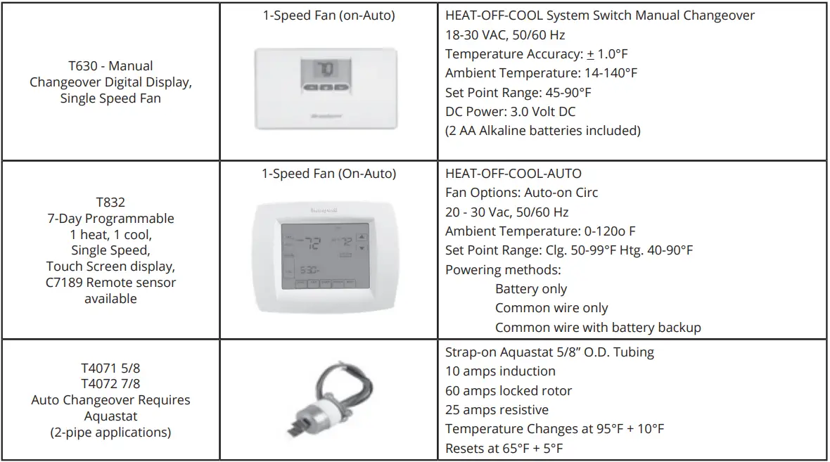
3-SPEED ROTARY SWITCH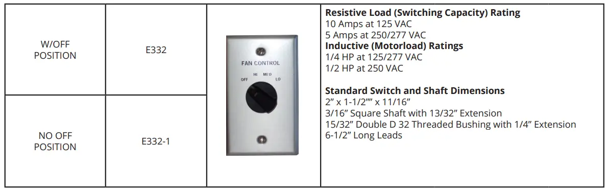
WALL MOUNT 3-SPEED SWITCH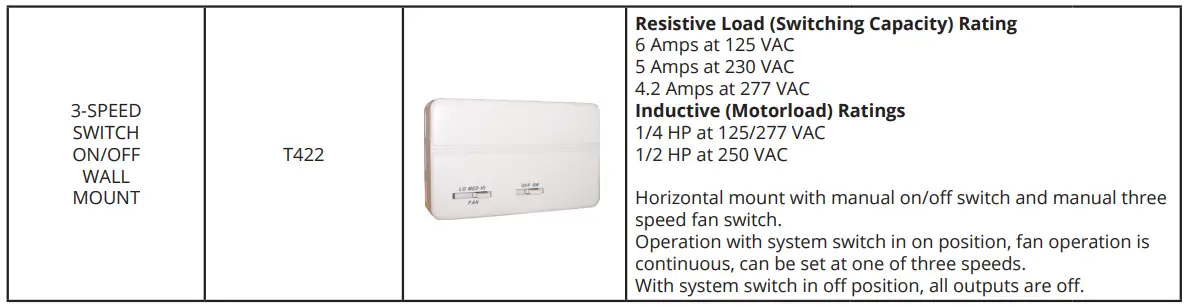
OPTIONAL SERVICE SWITCH (15 AMP)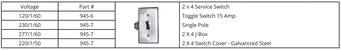
SINGLE SPEED FAN (24V Control Circuit)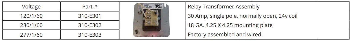
THREE SPEED FAN (24V Control Circuit)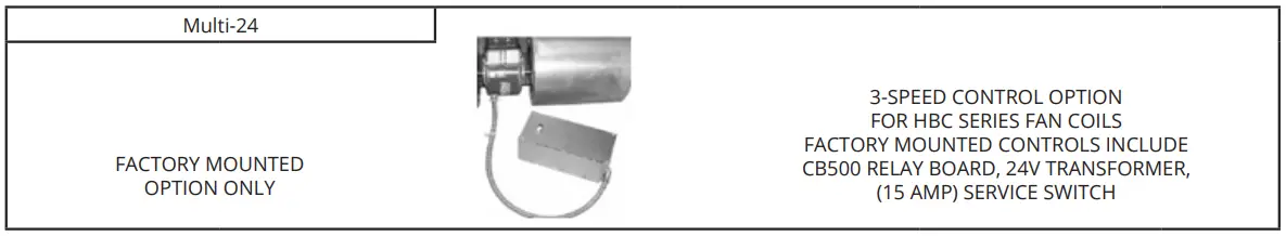
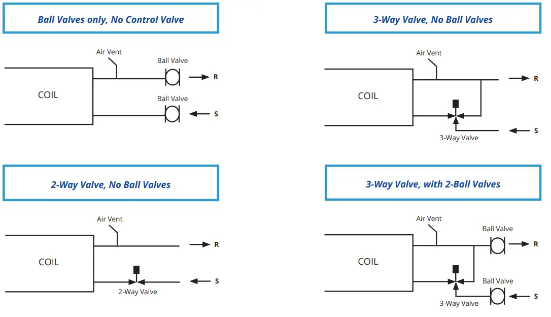
VALVE PACKAGES AND ACCESSORIES
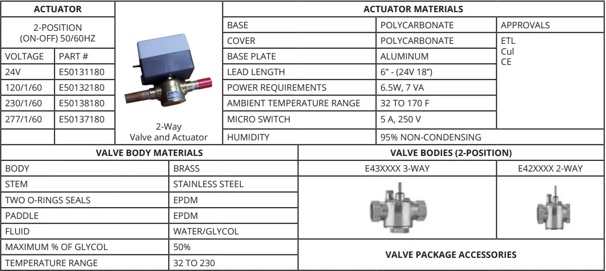
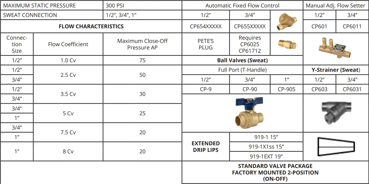
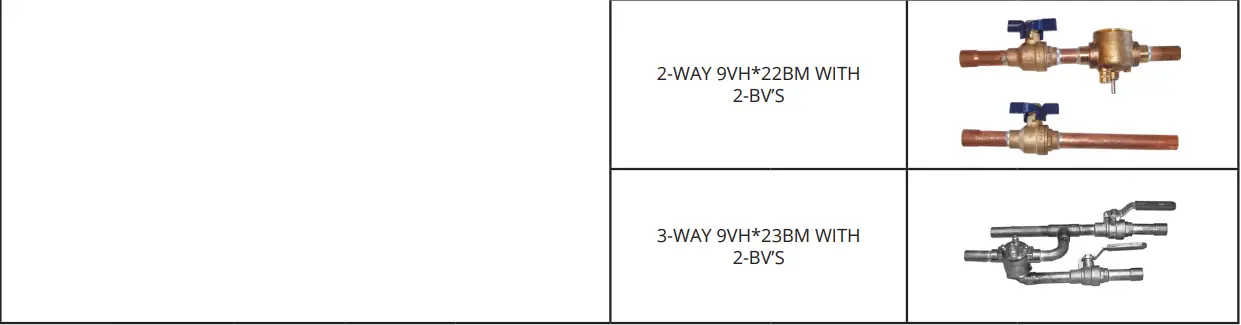
PIPING PACKAGE OPTIONS
TWO POSITION OR MODULATING
Manual air vents are standard and are factory mounted on all chilled water and hot water coils. All pre-piped on/off or modulating valve packages are factory assembled with sweat connections.
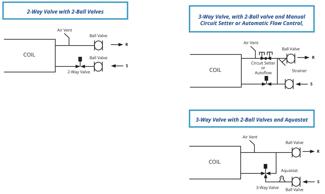
Add Options:
- Y-Strainers, Pete’s Plugs, Cleanout Blow-down, SS hose kits, Aquastats
- Additional options and configurations may be available. Contact factory for availability.
- Valve packages are available as kits or factory mounted on certain products. Contact factory for availability
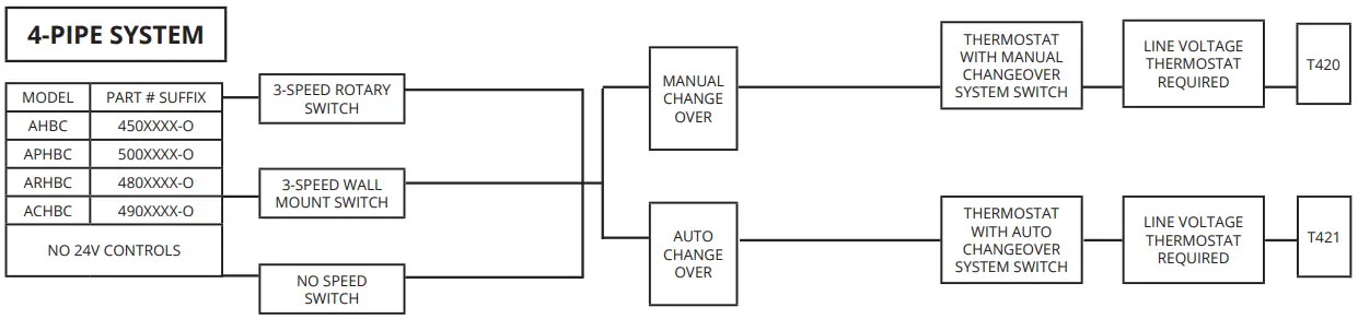
LOW VOLTAGE 24V CONTROLS
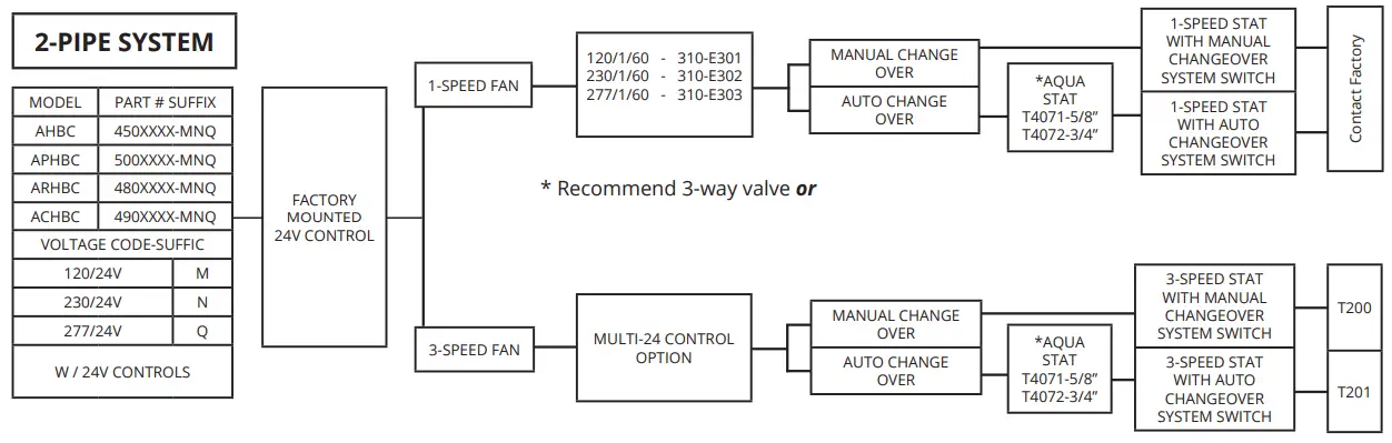
LINE VOLTAGE 120/230/277V CONTROLS
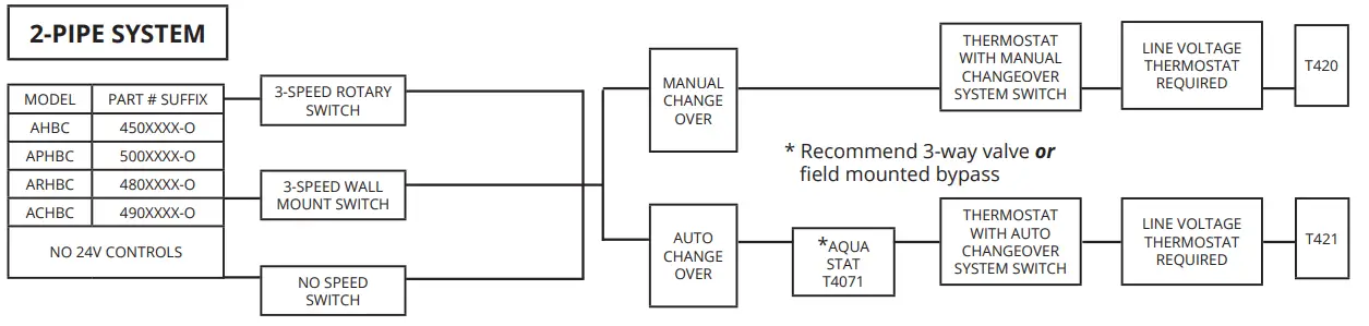
LOW VOLTAGE 24V CONTROLS
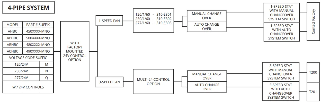
LINE VOLTAGE 120/230/277V CONTROLS
ABOUT COMPANY
- 8273 MOBERLY LANE, DALLAS, TX 75227
- [email protected]
- OFFICE: 214-388-5751
- FAX: 214-388-2255


