
ETi 64222401 2 ft. x 2 ft. Surface Mounting Kit for 2×2 LED Flat Panel
![]() NOTE: Keep your receipt and these instructions for proof of purchase.
NOTE: Keep your receipt and these instructions for proof of purchase.![]() WARNING: Shut off the power at the circuit breaker or fuse panel before removing the old fixture, ballast, or fluorescent tubes.
WARNING: Shut off the power at the circuit breaker or fuse panel before removing the old fixture, ballast, or fluorescent tubes.
If you are unfamiliar with electrical installations, we recommend you contact a qualified electrician to do the installation.![]() NOTE: Two people are recommended for installation of this light fixture.
NOTE: Two people are recommended for installation of this light fixture.
Package Contents
| Part | Description | Quantity |
| A | Fixture* | 1 |
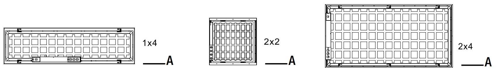
* 2×2 Flat Panel model numbers: 64222401/64222402/64222402-I/64222402-EM/64222402-I-EM
* 2×4 Flat Panel model numbers: 64224301/64224302/64224302-I/64224302-EM/64224302-I-EM
* 1×4 Flat Panel model numbers: 64214101/64214102/64214102-I/64214102-EM/64214102-I-EM
HARDWARE AVAILABLE TO PURCHASE
Hardware kits for surface mounting, recessed drywall mount and suspension mounting are sold as separate accessories. Please contact ETiSSL Customer Service 1-855-384-7754 for additional information.
| Part | Description | Quantity | Part # |
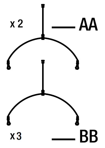
| AA | 2-Cable Suspension Mount Kit for 2’x2’ panel and 1’ x 4’ Flat Panel | 2 | 70317201 |
| BB | 3-Cable Suspension Mount Kit for 2’x4’ panel | 3 | 70317202 |
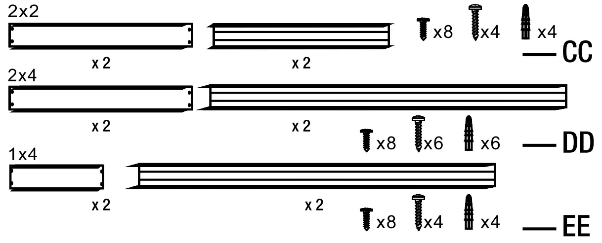
| CC | Surface Mounting Kit for 2’ x 2’ Flat Panel | 1 | 70317101 |
| DD | Surface Mounting Kit for 2’ x 4’ Flat Panel | 1 | 70317102 |
| EE | Surface Mounting Kit for 1’ x 4’ Flat Panel | 1 | 70317103 |
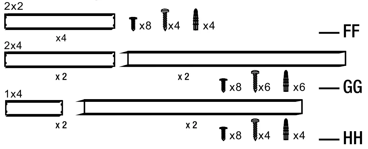
| FF | Recessed Drywall Mount Kit for 2’ x 2’ Flat Panel | 1 | 70319201 |
| GG | Recessed Drywall Mount Kit for 2’ x 4’ Flat Panel | 1 | 70319202 |
| HH | Recessed Drywall Mount Kit for 1’ x 4’ Flat Panel | 1 | 70319203 |
Surface Mounting Kits – CC DD and EE
Recessed Drywall Mount Kits – FF GG and HH
INSTALLATION
![]() CAUTION: Installer is responsible to ensure grid location is rated for fixture weight prior to installation. If uncertain, use cable to support fixture from the retention clips to a suitable support structure. Failure to do so can cause serious injury. Recessed Drywall Mount Kit are for Individual Units Mounts only, not suitable for continuous rows.
CAUTION: Installer is responsible to ensure grid location is rated for fixture weight prior to installation. If uncertain, use cable to support fixture from the retention clips to a suitable support structure. Failure to do so can cause serious injury. Recessed Drywall Mount Kit are for Individual Units Mounts only, not suitable for continuous rows.
Shut off power at the electrical panel before beginning the installation.
Remove existing fixture and set aside to recycle in accordance with local requirements.
Choose your favorite correlated color temperature (CCT) before installing the fixture. Left to right: 3000K/3500K/4000K/5000K
NOTICE: The factory setting for the correlated color temperature (CCT) is 4000K, which is the cool white.
Choose the desired brightness (lumen output).
NOTICE: The factory setting for the brightness (lumen output) is 4375lm (64222401/64222402/64222402-I/64222402-EM/64222402-I-EM/64214101/64214102/64214102 I/ 64214102-EM/64214102-I-EM), and 6250lm (Model # 64224301/64224302/64224302-I/64224302 EM/64224302-I-EM).
Making Electrical Connections
Remove the driver box cover plate and punch out the knock out hole.
Feed the conduit or Romex (based on local electrical code) through the knock out hole.
NOTE: It’s recommended to use 16GA pigtails from the terminal block to the respective power supply wires. Must add pigtail or jumper wires into the ACL and ACN terminal to use a wire larger than 16AWG for both AC and Neutral Line.
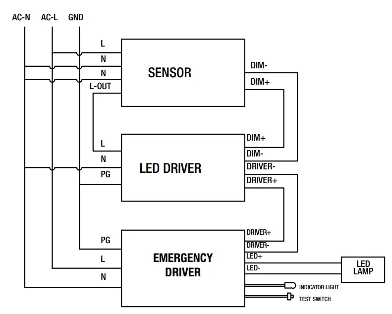
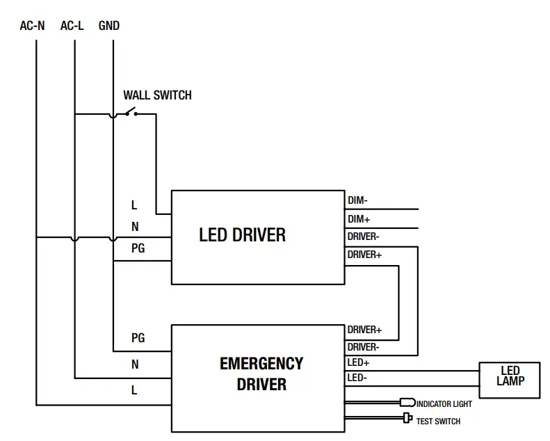
Make the electrical connections:
Connect black (L) wire with black wire in the driver.
Connect white (N) wire with white wire in the driver.
Connect ground wire with yellow wire in the driver.
If a 0-10v dimming circuit is available, connect fixture purple wire to driver DIM+ and gray fixture wire to driver DIM-. Tuck wires inside the driver box and reattach the driver cover.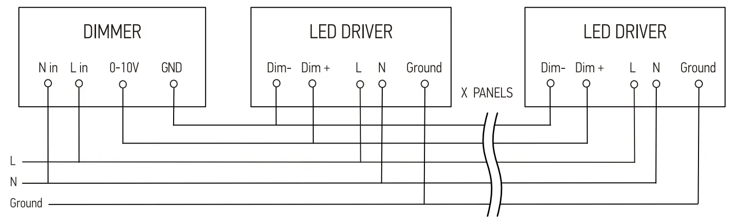
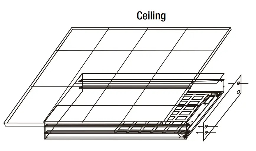
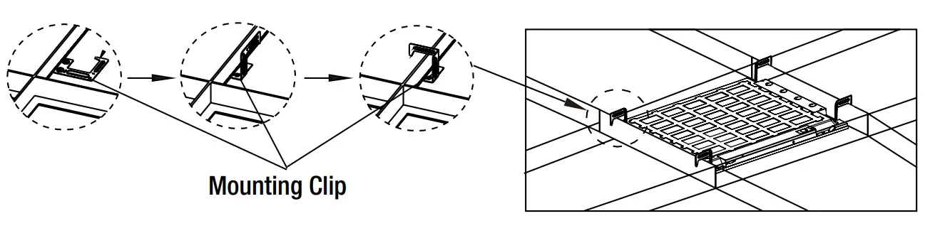
GRID CEILING INSTALLATION
CAUTION: Clip is used for positioning (NOT for mounting)
Bend each of the mounting clips on the back of the fixture upward and then twist the top 90°.
Place the fixture into the ceiling grid, hook the mounting clips over the grid ceiling supports and make sure it is secure.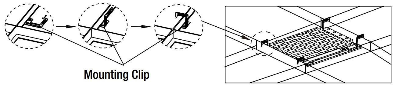
Suspension Mounting
Depending on mounting location, install 4 toggle bolts into drywall or 4 hook screws into wood.
NOTICE: Toggle bolts are not considered an acceptable means of support in Canada, in accordance with CSA C22.2 No. 250.4.
NOTICE: There are many installation applications to suspension mount the fixture. Installer is responsible to ensure mounting accessories and hardware are compatible with attachment method to surface or structure in accordance with any local code requirements for installation and inspection.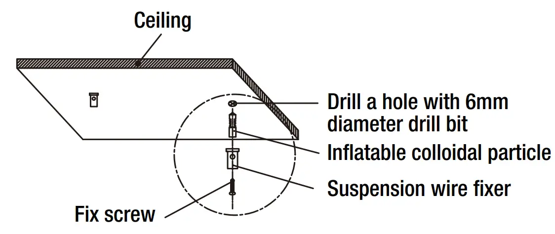
Attach the aircraft cable to the toggle bolts or hook screws
Bend each of the mounting clips on the back of the fixture upward.
Connect the mounting clips to the aircraft cables by using S hooks.
Adjust the aircraft cables to level the fixture.
NOTICE: The LED flat panel must hang a minimum of 3 in. from the ceiling. Make the electrical connections. See Making Electrical Connections.
Restore power at the electrical panel.
Turn on the light switch to activate the fixture.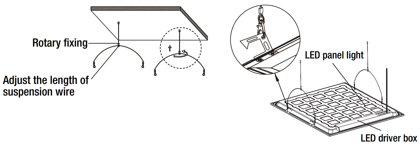
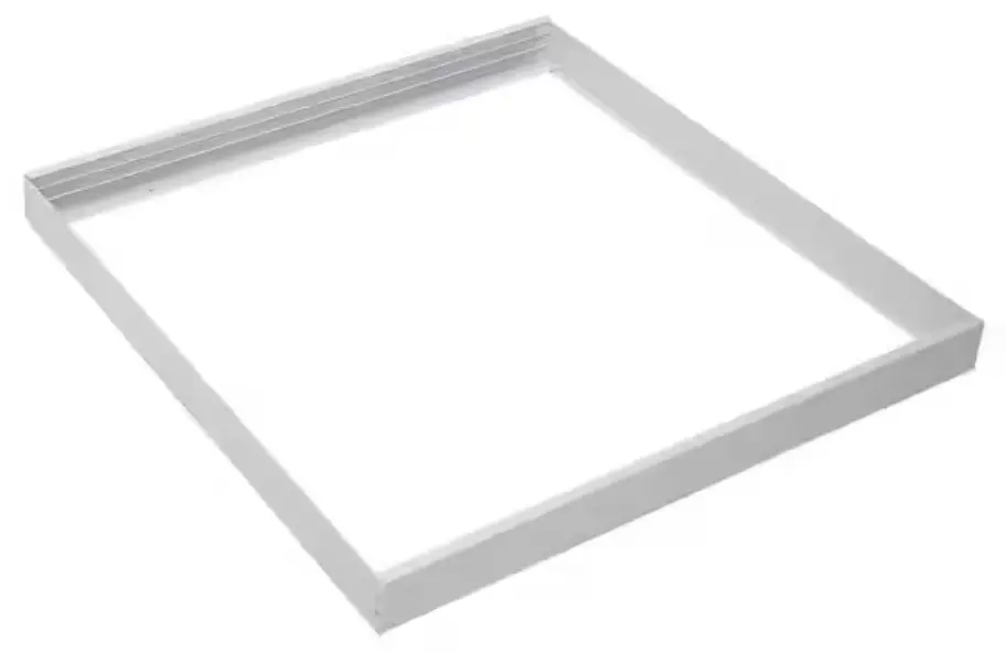
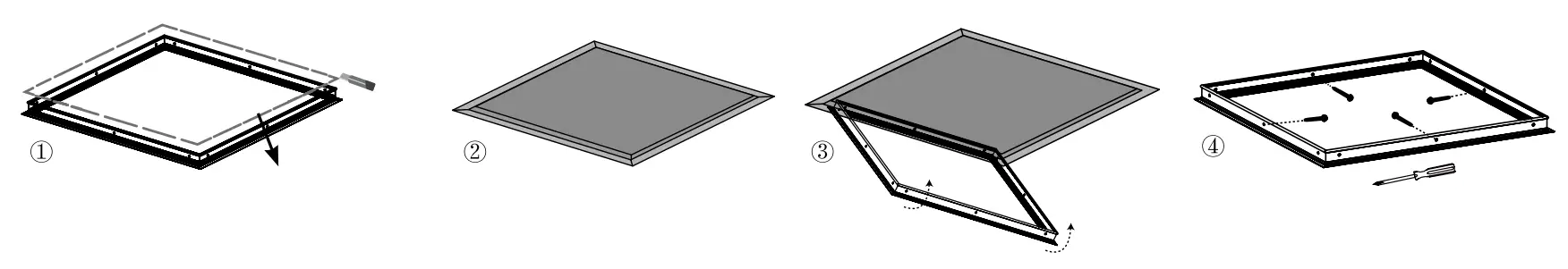
Surface Mounting
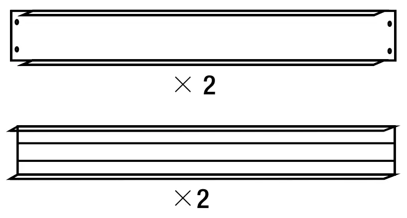
Use screws to assemble 3 sides of the surface mounting kit.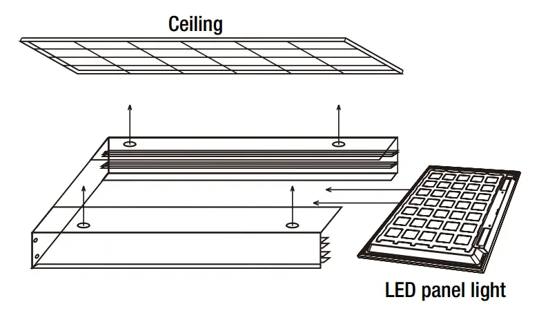
Slide the fixture into the surface mounting kit and use screws to secure the remaining piece of the surface mounting kit.
If installing into drywall, drill four 1/4 in. diameter holes into the ceiling, insert drywall anchors into the holes, and use screws to secure the surface mounting kit to the ceiling.
NOTICE: ETI surface mount kits can be applied to many installation applications. Installer is responsible to ensure kit compatibility with attachment method to surface or structure in accordance with any local code requirements for installation and inspection.
Make the electrical connections. See Making Electrical Connections.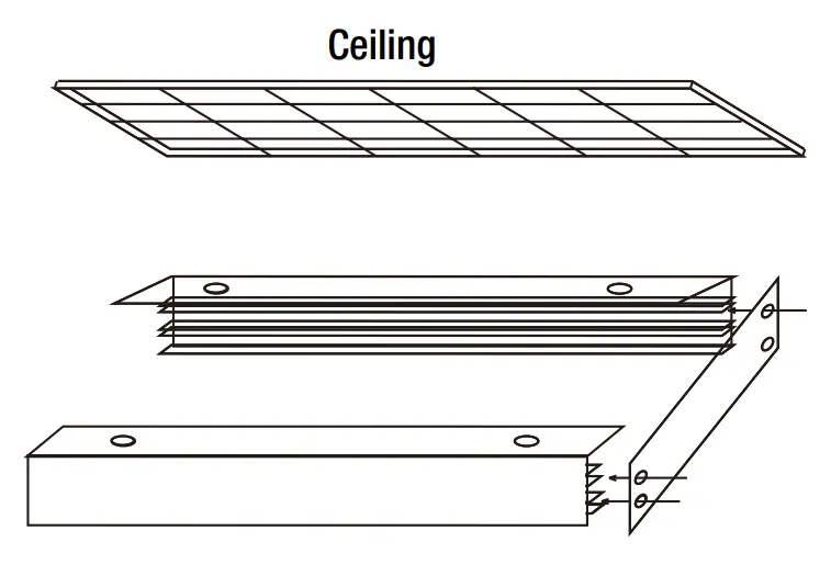
Restore power at the electrical panel. Turn on the light switch to activate the fixture.
RECESSED DRYWALL MOUNTING
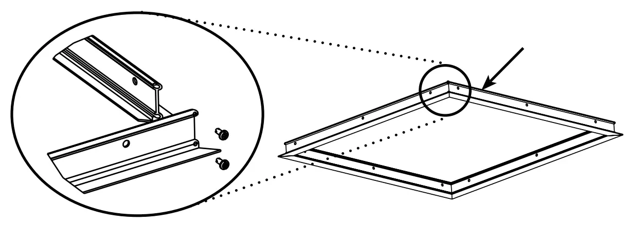
Assemble the four pieces of the drywall kit with the short screws provided.
Measure assembled inner frame dimension for cutting opening in the ceiling.
Opening dimension is 24 11/16” X 24 11/16” ( 627mm X 627mm) for 2’x2’ drywall mounting kit.
Opening dimension is 24 11/16” X 48 11/16” ( 627mm X 1237mm) for 2’x4’ drywall mounting kit.
Opening dimension is 12 51/64” X 48 11/16” ( 325mm X 1237mm) for 1’x4’ drywall mounting kit.
Cut an opening in the ceiling and frame out above the ceiling for support. Attached the assembled kit into ceiling with long screws provided.
Bend each of the mounting clips on the back of the fixture upward and then twist the top 90°, hook the mounting clips over the kit supports.
WARNING: Carefully read and understand the information given in this manual before beginning the assembly and installation. Failure to do so could lead to electric shock, fire, or other injuries which could be hazardous or even fatal.
- Ensure the electricity to the wires you are working on is shut off. Either remove the fuse or turn off the circuit breaker.
- Risk of Electric Shock
- Suitable for indoor and damp locations.
- Do not mount near flammable materials or electric heaters.
- Do not let power supply cords touch a hot surface.
- The product should be installed and operated by a qualified electrician or technician in accordance with relevant local codes.
- The final installation must be approved by the appropriate qualified electrical/building inspector(s).
NOTICE: This device complies with Part 15 of the FCC Rules. Operation is subject to the following two conditions: (1) this device may not cause harmful interference, and (2) this device must accept any interference received, including interference that may cause undesired operation. These limits are designed to provide reasonable protection against harmful interference in a residential installation. This equipment generates, uses and can radiate radio frequency energy and, if not installed and used in accordance with the instructions, may cause harmful interference to radio communications. However, there is no guarantee that interference will not occur in a particular installation. If this equipment does cause harmful interference to radio or television reception, which can be determined by turning the equipment off and on, the user is encouraged to try to correct the interference by one or more of the following measures: Reorient or relocate the receiving antenna, increase the separation between the equipment and the receiver, connect the equipment into an outlet on a circuit different from that to which the receiver is connected, and consult the dealer or an experienced radio/TV.
- Changes or modifications not expressly approved by the party responsible for compliance could void the user’s authority to operate the equipment. See website for Warranty, Troubleshooting or Care and Cleaning details at www.ETiSSL.com.
Questions, problems, missing parts? Call ETiSSL Customer Service 8 a.m. – 5 p.m., CST, Monday – Friday 1-855-ETI-SSLI (1-855-384-7754) www.ETiSSL.com