![]()
IS12-PD-ISO 5599-1 Valves and Valve Systems
Instruction Manual
IS12-PD-ISO 5599-1 Valves and Valve Systems
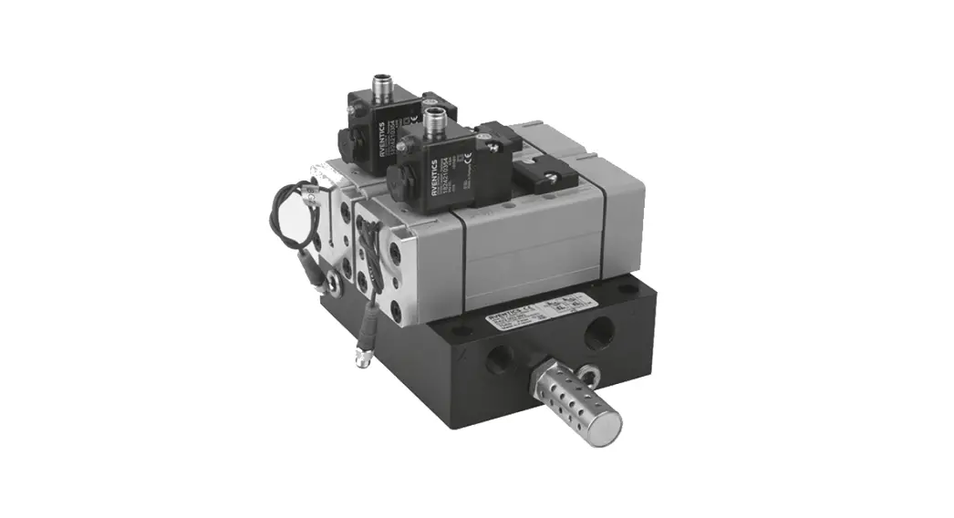
![]() Figures: View varies according to the series.
Figures: View varies according to the series.
 Device overview, material number R422003622–625
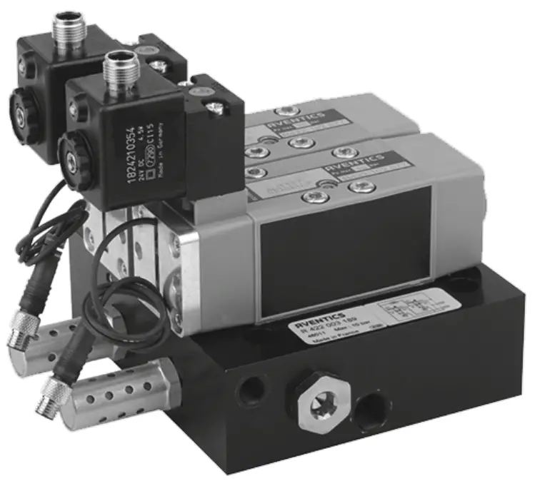
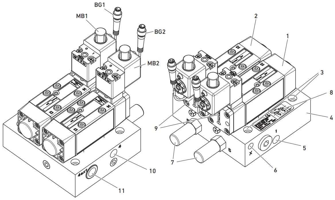 Device overview, material number R422003189–192
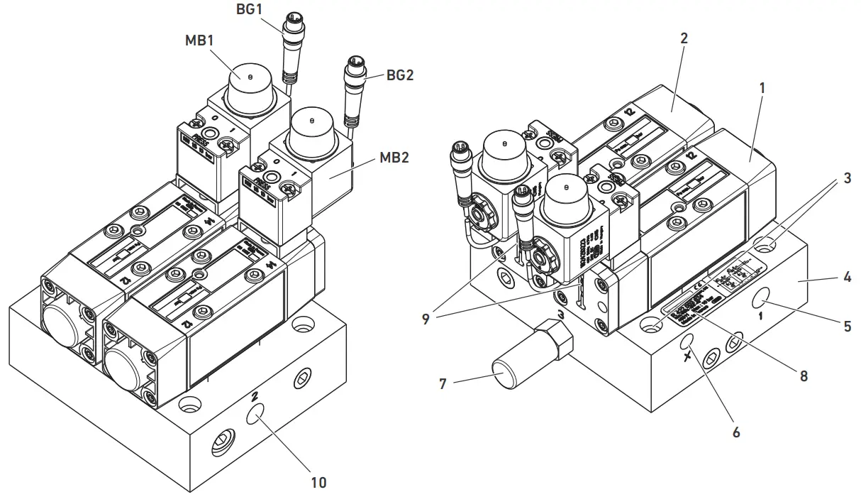
 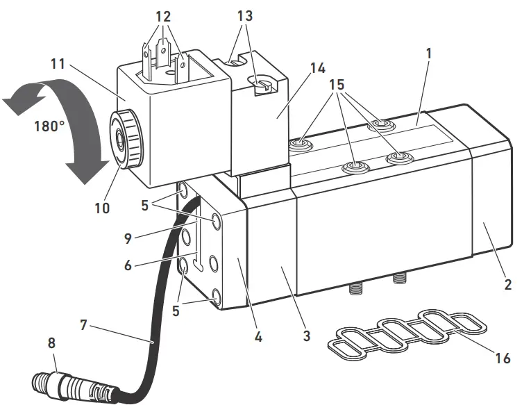 Device overview IS12-PD
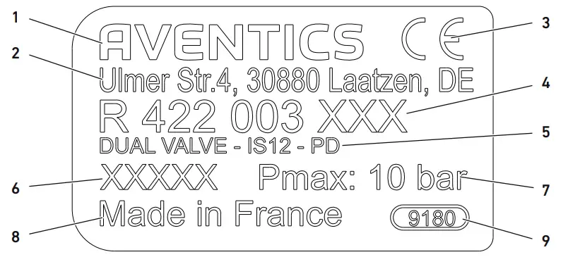 Name plate
- Company name
- Company address
- CE mark
- Material number
- Type designation
- Production date
- Maximum pressure
- Country of manufacture
- Responsible plant
Internal pilot 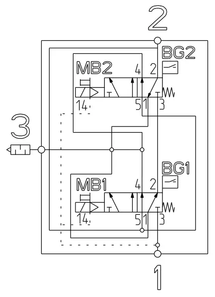 External pilot
 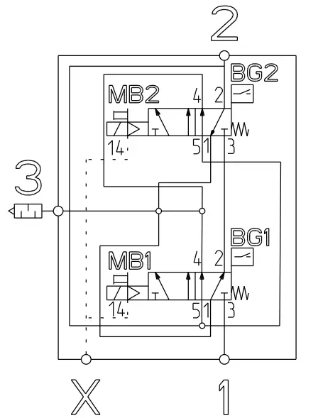 Wiring diagram for variants R422003622–625, internal pilot (left) and external pilot (right)
Internal pilot
External pilot 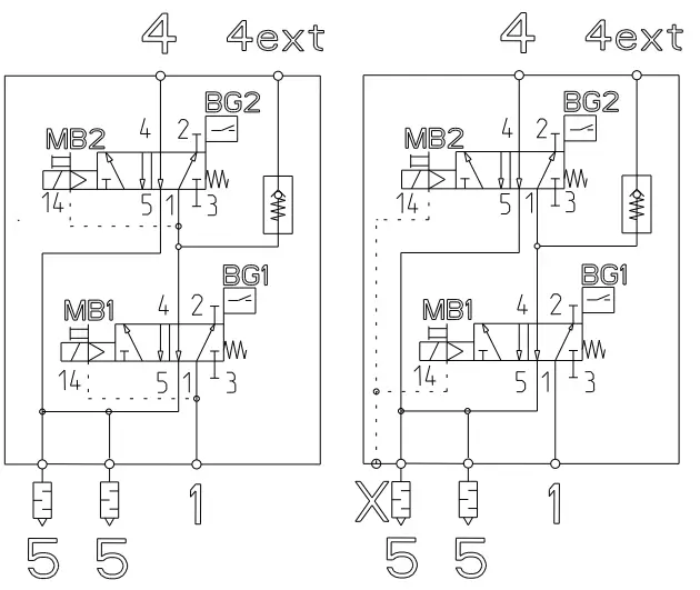 Wiring diagram for variants R422003189–192, internal pilot (left) and external pilot (right)
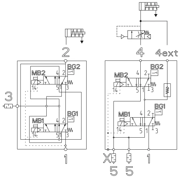 Application examples: left without non-return valve, right with non-return valve
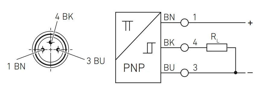 Pin assignments for the M8x1 sensor plug
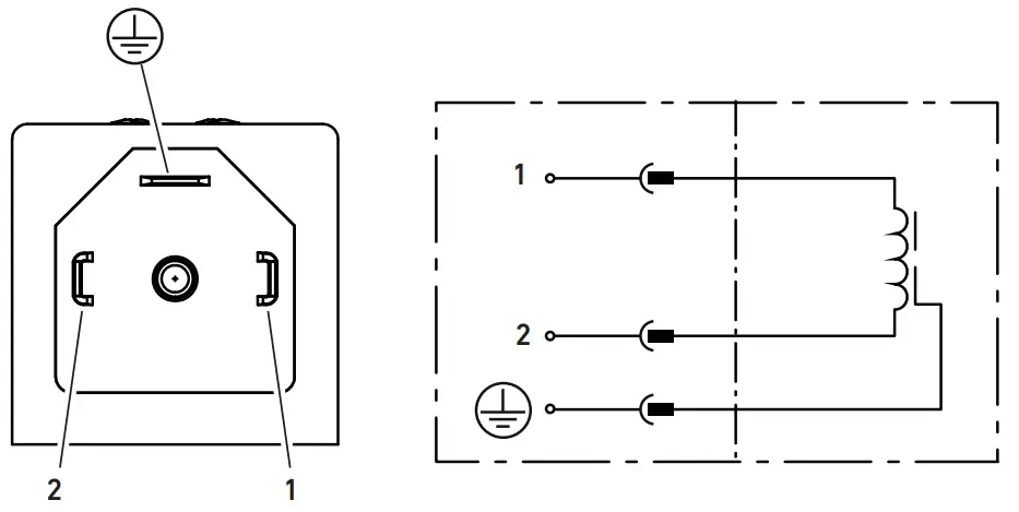 Pin assignment for coil, form A, series CN1
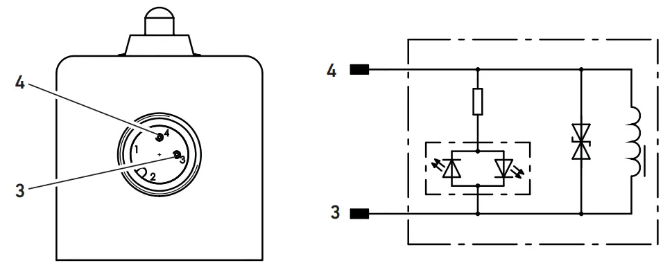 Pin assignment for coil M12 in accordance with ISO 20401
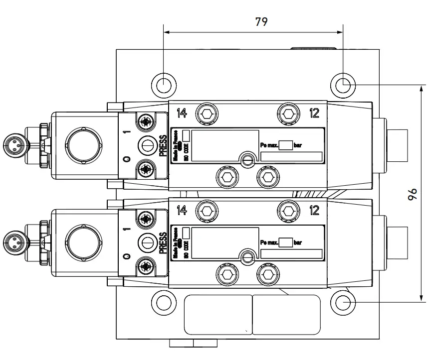 Distances of mounting holes
About This Documentation
Documentation validity
This documentation applies to the following dual valve variants (two electrically operated pneumatic 5/2 directional valves, IS12-PD series, size 1, with slider position detection)
| Material number (single valve) | Coil | MO | Pilot | Non-return valve |
| R422003622 (R422102677) | 24 V DC M12 | Without detent | External | No |
| R422003623 (R422102677) | 24 V DC M12 | Without detent | Internal | No |
| R422003624 (R422002577) | 24 V DC M12 | Without detent | External | No |
| R422003625 (R422002577) | 24 V DC form A | Without detent | Internal | No |
| R422003189 (R422102677) | 24 V DC form A | Without detent | External | Yes |
| R422003190 (R422102676) | 24 V DC M12 | Without detent | Internal | Yes |
| R422003191 (R422002577) | 24 V DC form A | Without detent | External | Yes |
| R422003192 (R422002521) | 24 V DC form A | Without detent | Internal | Yes |
This documentation is intended for installers, operators, service technicians, and systems owners.
This documentation contains important information on the safe and appropriate transport, assembly, commissioning, and maintenance of the product.![]() Read this documentation completely, especially chapter “2 Notes on Safety” before working with the product.
Read this documentation completely, especially chapter “2 Notes on Safety” before working with the product.
This product is provided with a CE mark. The EC declaration of conformity is included in the operating instructions.
Required documentation
The dual valve is a system component.![]() Also observe the instructions for the other system components and manufacturer’s system documentation.
Also observe the instructions for the other system components and manufacturer’s system documentation.
Presentation of information
Safety instructions
In this documentation, there are safety instructions before the steps whenever there is a risk of personal injury or damage to equipment. The measures described to avoid these hazards must be followed. Safety instructions are set out as follows:
SIGNAL WORD
Hazard type and source
Consequences of non-observance![]() Measures to avoid these hazards
Measures to avoid these hazards
- Safety sign (warning triangle): draws attention to the risk
- Signal word: identifies the degree of hazard
- Hazard type and source: identifies the hazard type and source
- Consequences: describes what occurs when the safety instructions are not complied with
- Precautions: states how the hazard can be avoided
Meaning of the signal words
Hazard classes according to ANSI Z 535.6-2006![]() DANGER
DANGER
Indicates a hazardous situation which, if not avoided, will certainly result in death or serious injury.![]() WARNING
WARNING
Indicates a hazardous situation which, if not avoided, could result in death or serious injury.![]() CAUTION
CAUTION
Indicates a hazardous situation which, if not avoided, could result in minor or moderate injury.![]() NOTICE
NOTICE
Indicates that damage may be inflicted on the product or the environment.
Symbols
The following symbol indicates information that is not relevant for safety but that helps in comprehending the documentation.
Symbol Meaning![]() If this information is disregarded, the product cannot be used or operated optimally.
If this information is disregarded, the product cannot be used or operated optimally.
Abbreviations
This documentation uses the following abbreviation
| Abbreviation | Meaning |
| CCF | Common Cause Failure |
| DC | Diagnostic coverage |
| MO | Manual override |
| PL | Performance level |
| PLr | Required performance level |
| SF | Safety function |
Notes on Safety
About this chapter
The product has been manufactured according to the accepted rules of current technology. Even so, there is risk of injury and damage to equipment if the following chapter and safety instructions of this documentation are not followed.![]() Read these instructions completely before working with the product.
Read these instructions completely before working with the product.![]() Keep this documentation in a location where it is accessible to all users at all times.
Keep this documentation in a location where it is accessible to all users at all times.![]() Always include the documentation when you pass the product on to third parties.
Always include the documentation when you pass the product on to third parties.
Intended use
The dual valve is a safety component in accordance with Machinery Directive 2006/42/EC and is therefore provided with the CE mark. The intended use is the exhaust in compressed air systems or equivalent applications and the prevention of unexpected start-ups.![]() See section 16 “Technical Data” for the standards and test values complied with and adhered to by the product.
See section 16 “Technical Data” for the standards and test values complied with and adhered to by the product.![]() The pressure regulator may only be used within the limits listed in the technical data. The product is intended for professional use only.
The pressure regulator may only be used within the limits listed in the technical data. The product is intended for professional use only.
Intended use includes having read and understood this documentation, especially the chapter 2 “Notes on Safety”.
Safety function according to ISO 13849
The dual valve is a redundant system according to the requirements of ISO 13849-1 and -2, in which the pneumatic safety functions “safe exhaust” and “prevention of unexpected start-ups” are ensured, including in case of a valve fault (e.g. due to wear).
With correct integration in the control system in accordance with ISO 13849-1 and -2, these products can be used in up to category 3 and 4 and a performance level up to e can be achieved. The valves used have a slider position detection and improve the diagnostic coverage level of the control.
The product has been engineered and manufactured according to the fundamental and proven safety principles of ISO 13849-2.
Common Cause Failure – CCF
The following measures must be ensured by the user to prevent failures due to common causes:
- Observe the temperature range (see chapter 16 “Technical Data”)
- Observe the compressed air quality (see chapter 10 “Operation”)
- Observe the permissible operating pressure (see chapter 16 “Technical Data”)
- Observe the permissible voltage and current range for coils and sensor (see chapter 16 “Technical Data”)
Proper use of this product also includes the user knowing and implementing all further requirements from ISO 13849-1 and -2 (e.g. measures for the software, diagnosis, against further CCF, against systematic failures etc.) and then evaluating whether the necessary performance level has been achieved.
Improper use
WARNING:
Misuse may result in injury or damage.
The following applications are therefore prohibited:
- Use in non-industrial applications/residential areas,
- Outdoor use,
- Use outside of the product limits defined in the technical data,
- Unauthorized modifications,
- Use in reversible operation (reversing of supply and exhaust air),
- Vacuum operation,
- Use in ATEX certified areas,
- Use near to ferromagnetic parts (a safety clearance of 30 mm to the sensor must be maintained and magnetic fields must generally be avoided)
Any use other than that described under Intended use is improper and is not permitted. AVENTICS GmbH is not liable for any damages resulting from improper use. The user alone bears the risks of improper use of the product.
Personnel qualifications
The work described in this documentation requires basic mechanical, electrical and pneumatic knowledge, as well as knowledge of the appropriate technical terms. In order to ensure safe use, these activities may therefore only be carried out by qualified technical personnel or an instructed person under the direction and supervision of qualified personnel.
Qualified personnel are those who can recognize possible hazards and institute the appropriate safety measures, due to their professional training, knowledge, and experience, as well as their understanding of the relevant regulations pertaining to the work to be done. Qualified personnel must observe the rules relevant to the subject area.
General safety instructions
- Observe the regulations for accident prevention and environmental protection.
- Observe the safety instructions and regulations of the country in which the product is used.
- Only use dual valves that are in perfect working order.
- Follow all the instructions on the product.
- Persons who assemble, operate, disassemble, or maintain the dual valve must not consumany alcohol, drugs, or pharmaceuticals that may affect their ability to respond.
- Only use accessories and spare parts approved by the manufacturer.
- Comply with the technical data and ambient conditions listed in the product documentationW
- If unsuitable products are installed or used in safety-relevant applications, this may result inuncontrolled system operating states that may lead to injuries or equipment damage. Therefore, only use a product in safety-relevant applications if such use is specifically stated and permitted in the product documentation. W You may only commission the product if you have determined that the end product (such as a machine or system) in which the AVENTICS products are installed meets the countryspecific provisions, safety regulations, and standards for the specific application.
Safety instructions related to the product and technology
WARNING
Danger of injury due to stored energy (compressed air) and voltage!
When the system is at a standstill, there is still a danger due to stored energy (compressed air) and voltage.![]() Generally avoid storing compressed air.
Generally avoid storing compressed air.![]() Make sure that the relevant system part is not under voltage or pressure before you assemble or disassemble the product.
Make sure that the relevant system part is not under voltage or pressure before you assemble or disassemble the product.![]() Exhaust the system before working on it.
Exhaust the system before working on it.![]() Always protect the system against being switched on.
Always protect the system against being switched on.![]() Remove all other sources of danger in the immediate work area that may result from stored energy in the system.
Remove all other sources of danger in the immediate work area that may result from stored energy in the system.
Danger of injury by dismantling the dual valve or valve!
Pre-tensioned springs may suddenly be released when dismantling.![]() Never disassemble the dual valve or valves.
Never disassemble the dual valve or valves.![]() Never unscrew the non-return valve found in connection 4 ext ( –11).
Never unscrew the non-return valve found in connection 4 ext ( –11).![]() Do not remove silencers on connection 5 ( –7, –7) to avoid changing the specified noise level.
Do not remove silencers on connection 5 ( –7, –7) to avoid changing the specified noise level.![]() Do not remove the mounting screws for the valve cover ( –2, 3).
Do not remove the mounting screws for the valve cover ( –2, 3).![]() Do not remove the mounting screws for the pilot valve ( –13).
Do not remove the mounting screws for the pilot valve ( –13).![]() Do not remove the mounting screws for the sensor housing ( –5).
Do not remove the mounting screws for the sensor housing ( –5).![]() Do not replace or disassemble the sensor, or change its position.
Do not replace or disassemble the sensor, or change its position.
Injuries if system-specific limits are not complied with!
The operating conditions for the dual valve may deviate from the system operating conditions.![]() Always observe the information in the documentation for the superior system.
Always observe the information in the documentation for the superior system.![]() Before assembly, contact the system manufacturer or AVENTICS GmbH to clarify any contradictions or questions.
Before assembly, contact the system manufacturer or AVENTICS GmbH to clarify any contradictions or questions.
Danger of burns caused by hot surfaces!
Touching the surfaces of the dual valve and adjacent components during operation could cause burns.![]() Let the relevant system component cool down before working on the dual valve.
Let the relevant system component cool down before working on the dual valve.![]() Do not touch the relevant system component during operation.
Do not touch the relevant system component during operation.
Risk of injury due to loss of the safety function!
Depending on the application, you must take appropriate measures to ensure the safety function.![]() When implementing safety measures against switch-off surges, check whether these extend the valve’s switch-off time.
When implementing safety measures against switch-off surges, check whether these extend the valve’s switch-off time.![]() Check if the valve’s electrical connection cables have to be routed separately.
Check if the valve’s electrical connection cables have to be routed separately.![]() In case of high levels of machine vibrations, use appropriate vibration-reducing elements when mounting the dual valve.
In case of high levels of machine vibrations, use appropriate vibration-reducing elements when mounting the dual valve.![]() Avoid overvoltages. These result in solenoid burnout.
Avoid overvoltages. These result in solenoid burnout.
The dual valve comes with a special silencer that complies with the requirements of ISO 13849 and which features a design that largely prevents clogging.![]() Only use the dual valve with a properly mounted silencer.
Only use the dual valve with a properly mounted silencer.![]() Make sure that the silencer’s flow capacity is not restricted. This would impair valve performance.
Make sure that the silencer’s flow capacity is not restricted. This would impair valve performance.![]() Only replace the silencer with a corresponding model (AVENTICS material number R412010246).
Only replace the silencer with a corresponding model (AVENTICS material number R412010246).
Personal protective equipment![]() Wear appropriate protective clothing during assembly and maintenance. Observe the applicable occupational safety regulations for the system.
Wear appropriate protective clothing during assembly and maintenance. Observe the applicable occupational safety regulations for the system.
Obligations of the system owner
As the owner of a system that will be equipped with a dual valve you are responsible for
- ensuring intended use,
- ensuring that operating employees receive regular instruction,
- ensuring that the operating conditions are in line with the requirements for the safe use of the product,
- ensuring that no unauthorized repairs are attempted if there is a malfunction. Other requirements of the operator:
![]() Observe the information on assembly and operating conditions listed in the operating instructions or the data sheet.
Observe the information on assembly and operating conditions listed in the operating instructions or the data sheet.![]() Comply with the further requirements of ISO 13849 (e.g. CCF, DC, PLr , software) if you intend to use the product in higher categories (2 to 4).
Comply with the further requirements of ISO 13849 (e.g. CCF, DC, PLr , software) if you intend to use the product in higher categories (2 to 4).![]() Make sure that the maximum number of switching cycles (B10d) within the service life TM (typical assumption as per ISO 13849-1 = 20 years) is not exceeded. If the expected number of switching cycles for a component exceeds the B10d value during its period of use, suitable exchange intervals have to be specified.
Make sure that the maximum number of switching cycles (B10d) within the service life TM (typical assumption as per ISO 13849-1 = 20 years) is not exceeded. If the expected number of switching cycles for a component exceeds the B10d value during its period of use, suitable exchange intervals have to be specified.![]() Switch the valve at least once a month to ensure its proper function.
Switch the valve at least once a month to ensure its proper function.![]() Make sure that the fundamental and proven safety principles in accordance with ISO 13849 for implementation and operation of the component are complied with.
Make sure that the fundamental and proven safety principles in accordance with ISO 13849 for implementation and operation of the component are complied with.![]() Make sure that the permissible positive and negative test pulses for feedback-free operation of the pneumatic devices are observed. (see chapter 16 “Technical Data”).
Make sure that the permissible positive and negative test pulses for feedback-free operation of the pneumatic devices are observed. (see chapter 16 “Technical Data”).
General Instructions on Equipment and Product Damage
NOTICE
Dual valve damage due to falling!
If the module falls, the product may be damaged even if no damage is visible.![]() Always transport the module carefully.
Always transport the module carefully.![]() If the module has fallen, it may no longer be installed.
If the module has fallen, it may no longer be installed.![]() Check the packaging when you receive the product. If the packaging is damaged, the module must not be installed.
Check the packaging when you receive the product. If the packaging is damaged, the module must not be installed.
Delivery Contents
The scope of delivery includes:
- 1 dual valve (valve, size 1, with mounted and adjusted ST4 sensor with M8x1 connection)
- 1 set of operating instructions
Device Description
Product identification
Check the material number of the dual valve (1 –8 ,2 –8) on the name plate, which can be found on the base plate, to determine whether the product matches your order (for details on the name plate see 4.
The production date consists of five numbers, with the first 3 digits showing the production year and production month and the last two digits stating the day of production. The following table shows our coding for the first 3 digits:
| Year | Jan | Feb | Mar | Apr | May | Jun | Jut | Aug | Sep | Oct | Nov | Dec |
| 2014 | 417 | 418 | 419 | 420 | 453 | 454 | 455 | 456 | 457 | 458 | 459 | 460 |
| 2015 | 517 | 518 | 519 | 520 | 553 | 554 | 555 | 556 | 557 | 558 | 559 | 560 |
| 2016 | 617 | 618 | 619 | 620 | 653 | 654 | 655 | 656 | 657 | 658 | 659 | 660 |
| … | ||||||||||||
| 2019 | 917 | 918 | 919 | 920 | 953 | 954 | 955 | 956 | 957 | 958 | 959 | 960 |
| 2020 | 37 | 38 | 39 | 40 | 73 | 74 | 75 | 76 | 77 | 78 | 79 | 80 |
| 2021 | 137 | 138 | 139 | 140 | 173 | 174 | 175 | 176 | 177 | 178 | 179 | 180 |
| … | ||||||||||||
| 2029 | 937 | 938 | 939 | 940 | 973 | 974 | 975 | 976 | 977 | 978 | 979 | 980 |
| 2030 | 41 | 42 | 43 | 44 | 45 | 46 | 47 | 48 | 49 | 44 | 04B | OAC |
| 2031 | 141 | 142 | 143 | 144 | 145 | 146 | 147 | 148 | 149 | 144 | 14B | 14C |
| … | ||||||||||||
| 2040 | OB1 | OB2 | OB3 | OB4 | OB5 | OB6 | OB7 | OB8 | OB9 | OBA | OBB | OBC |
| 2041 | 1B1 | 1B2 | 1B3 | 1B4 | 1B5 | 1B6 | 167 | 1B8 | 1B9 | 1BA | 1BB | 1BC |
| 2042 | 2B1 | 2B2 | 2B3 | 2B4 | 2B5 | 2B6 | 2B7 | 2B8 | 2B9 | 2BA | 2BB | 2BC |
Dual valve1 2
| 1 Valve 1: IS12-PD | 7 Exhaust ports with silencer |
| 2 Valve 2: IS12-PD | 8 Label |
| 3 Mounting screws 4 x Ø 6.4 mm for M6 screws | 9 Sensor LED |
| 4 Base plate | 10 Working connection 2 or 4, G1/4 |
| 5 Connection 1, G1/4 | 11 Connection 4 ext, G1/4 (for non-return valve) |
| 6 External pilot connection G1/8 |
Valve IS12-PD 3
| 1 Valve | 9 Sensor LED |
| 2 Valve cover, valve side 12 | 10 Coil lock nut |
| 3 Valve cover, valve side 14 | 11 Coil |
| 4 Sensor housing, bolted to valve cover (3) | 12 Contact for connecting an electrical connector |
| 5 Mounting screws for the sensor housing | 13 Mounting screws for the pilot valve |
| 6 Sensor slot | 14 Pilot valve |
| 7 Sensor cable | 15 Mounting screws for valve |
| 8 Sensor plug | 16 Base plate gasket |
Function Description
Dual valve
The dual valve includes two IS12-PD valves with slider position detection and can fulfill the two following safety functions:
- SF1: Safe exhaust
- SF2: Prevention of unexpected start-up
The dual valve is available in two different configurations: without and with integrated non-return valve (see Fig. and 5). 6 A system that is connected to working connection 2 of the dual valve (or 4 for the variant with non-return valve) of the dual valve is protected against unexpected start-up and can be safely exhausted. It is also possible to choose a variant with integrated nonreturn valve, to secure a start-up valve connected to connection 4 of the dual valve for example, as shown in Fig. on the right.
In addition to the dual channel design, the valves are equipped with a slider position detection (see “Valve with position detection” for details) to improve the diagnostic coverage level. Both sensors emit a signal (supply voltage) when working perfectly. One of the valve does not emit a signal in case of malfunction. No further cycle must be performed in this case, otherwise the dual duct capacity can no longer be ensured. It is not sufficient to check whether the sensor signal shows ON after switching the valves off. With each cycle, it must be checked whether the sensor signal changes from OFF to ON.
Both safety functions are described in more detail in the following. The rocedure to test the safety functions is explained in chapter 9 “Commissioning”.
SF1: Safe exhaust
Both valves are electrically switched off to exhaust a system connected to the dual valve.
Variant without non-return valve
In fault-free operation, the exhaust from the connected system can be exhausted via dual ducts, using both connection 1 of valve 2 (sensor and coil labeled with BG2 or MB2) or via connection 4 of valve 1 (sensor and coil labeled with BG1 or MB1).
If valve 2 does not allow any more exhausting, the air can escape via valve 1 and vice versa. Furthermore, if valve 2 remains in the closed position (valve connection 2 remains connected with valve connection 3), the exhaust air can escape through connection 2 of valve 1 via connection 3 of the dual valve.
Variant with non-return valve
In fault-free operation, the exhaust from the connected system can be exhausted via dual ducts, both via connection 5 of valve 2 or via connection 5 of valve 1.
If valve 2 does not allow any more exhausting, the air can escape via valve 1 and vice versa. Furthermore, if valve 2 remains in the switched position (valve connection 4 remains connected with valve connection 1), the exhaust air can escape through connection 4 of valve 1 via connection 5 of the dual valve.
The exhaust duct on the system to be secured must be connected with connection 4 and 4 ext of the dual valve. Even if connection 4 ext is not required, this must be connected (add connection between connection 4 and 4 ext of the dual valve) to ensure dual duct exhaust.
The non-return valve function is not monitored. The requirements of category 3 or 4 are not fulfilled. The variant with non-return valve is therefore classified in category 1 and a maximum PL = c can be achieved.
SF2: Prevention of unexpected start-up
Both valves are switched without current with this function (when working perfectly). Even if one of the two valves is unintentionally switched on, the system connected to the dual valve is not pressurized.
Variant without non-return valve
Series connection of both valves allows double protection against unexpected start-up. If valve 1 pressurizes valve connection 2, pressurization of the overall system is still prevented by the blocked valve connection 2 of valve 2. If valve 2 switches unintentionally, the air supply is still prevented by valve 1, i.e. connection 2 of the dual valve is not pressurized.
Variant with non-return valve
If valve 1 pressurizes valve connection 2, connections 4 and 4 ext of the dual valve are still disconnected from the compressed air supply because valve 2 and the non-return valve block the compressed air supply.
In case of a malfunction of valve 2 or the non-return valve, the air supply is still blocked by valve 1 i.e. connections 4 and 4 ext of the dual valve are not pressurized. The non-return valve is not position monitored. If you require a PL e, you can undertake fault exclusion for the IS12-PD valves for independent change of the output switching position (without input signal).
Valve with position detection 3
IS12-PD series valves are electrically operated pneumatic 5/2 directional valves with an integrated slider position detection. Slider position detection is realized by means of the following system: A magnet is integrated in the piston (slider) of the valve and an ST4 series proximity sensor with an M8x1 connection is installed in a sensor housing on valve side 14.
The sensor LED indicates the position of the slider. This allows the user to detect whether the valve is in the home position (sensor LED is lit) or in the switching state (sensor LED is not lit). In addition, the position of the sensor is transferred to the controller via the M8 connection, PIN 4 (OUT).
The sensor is switched on when the slider is located on valve side 14, meaning in home position. In this case, the sensor LED is lit. The sensor is switched off when the slider is located on valve side 12, i.e. in the switching position. In this case, the sensor LED is not lit.
Home position, sensor LED lit
When the valve is not actuated electrically, it is in home position. The slider is positioned so that connections 1 and 2 and connections 4 and 5 are connected respectively. With typical use, connection 2 is under pressure while connection 4 is pressure-free. The sensor LED is switched on and indicates that the valve is in the home position. The output voltage is applied to pin 4 (OUT). To ensure the system is not under pressure in home position, the working connection to the system must be connected at connection 4.
Switching position, sensor LED not lit
When the valve is actuated electrically, it is in switching position. The slider is positioned so that connections 2 and 3 and connections 1 and 4 are connected respectively. With typical use, connection 2 is pressure-free while connection 4 is under pressure. The sensor LED is switched off and indicates that the valve is in the switching position. 0 volts are applied to pin 4 (OUT). To ensure the system is under pressure in the switching position, the working connection to the system must be connected at connection 4.
Change of sensor signal when pressurizing working connection 2 or 4
When the valve is switched on, the slider moves from valve side 14 to valve side 12 (see number 2 and 3 in Fig.). During slider movement, the signal of the sensor switches from “ON” to “OFF”. 3
Change of sensor signal when exhausting working connection 2 or 4
When the valve is switched off, the slider moves from valve side 12 to valve side 14. During slider movement, the signal of the sensor switches from “OFF” to “ON” if connection 2 is connected to connection 1 or connection 4 is connected to connection 5.
Transport and Storage
![]() The dual valve is packaged to protect it from contamination. Do not remove the packaging until just before assembling the valve.
The dual valve is packaged to protect it from contamination. Do not remove the packaging until just before assembling the valve.
Transport
CAUTION
Danger of injury from falling!
The dual valve can weigh up to 2400 g and cause injury if it falls.![]() Always transport the dual valve carefully.
Always transport the dual valve carefully.![]() Wear suitable protective clothing, such as safety shoes.
Wear suitable protective clothing, such as safety shoes.
NOTICE
Dual valve damage due to falling!
If the dual valve falls, the product may be damaged even if no damage is visible.![]() Always transport the dual valve carefully.
Always transport the dual valve carefully.![]() If the dual valve has fallen, it must not be installed.
If the dual valve has fallen, it must not be installed.![]() Check the packaging when you receive the product. If the packaging is damaged, the dual valve must not be installed.
Check the packaging when you receive the product. If the packaging is damaged, the dual valve must not be installed.
Storage
NOTICE
Damage to the dual valve due to incorrect storage!
Unfavorable storage conditions can result in corrosion and material deterioration. The maximum storage period is two years.![]() Only store the dual valve in dry, cool, and corrosion-proof environments. Avoid direct sunlight.
Only store the dual valve in dry, cool, and corrosion-proof environments. Avoid direct sunlight.![]() Keep the dual valve in the original or delivery packaging if you do not install it immediately.
Keep the dual valve in the original or delivery packaging if you do not install it immediately.![]() Never use a dual valve that has been stored for longer than two years.
Never use a dual valve that has been stored for longer than two years.
Assembly
![]() WARNING
WARNING
Danger of injury due to assembly of the product while the system is running!
Assembly of the product while the system is running can cause major injuries from moving machinery.![]() Bring the system mode into a state in which working movements are no longer possible. Wait until all moving machine parts come to a standstill, and protect the system against being switched on.
Bring the system mode into a state in which working movements are no longer possible. Wait until all moving machine parts come to a standstill, and protect the system against being switched on.
Danger of injury due to suspended useful loads!
Useful loads that are kept suspended by compressed air pose a danger if they are not secured before the pressure is switched off in the system.![]() Guide the useful loads into a safe position or remove them from the system.
Guide the useful loads into a safe position or remove them from the system.![]() You may only then switch off the pressure in the relevant section of the system.
You may only then switch off the pressure in the relevant section of the system.
The following must be observed during assembly:
- The dual valve is packaged to protect it from contamination. Do not remove the packaging until just before assembling the dual valve.
- All compressed air connections and control elements must remain freely accessible after installation.
- The dual valve must be attached in such a way that it cannot be loosened by jolts, vibrations, or the like.
- The position of the sensor was fixed at the factory and secured with a clamping screw and resin. The sensor must not be replaced or disassembled, or its position changed. The sensor housing (4) is bolted to the valve cover (3) and secured with resin. The sensor housing must not be replaced or disassembled, or its position changed.
![]() Make sure that the dual valve is only used as described in “Intended use”.
Make sure that the dual valve is only used as described in “Intended use”.
Preparing for installation
Prepare for assembly as follows:
- Stop system operation and protect it against being switched on.
- Return all suspended loads to a statically secure position or remove them from the system.
- If required, exhaust stored compressed air from system parts in the immediate work area.
- Make sure the relevant section of the system is not under pressure or voltage and protect it from being switched on.
- Secure self-turning or other movable system parts before starting assembly.
- Before assembly, check the sensor cable for damage. If the sensor cable is damaged, you must replace the entire valve. In this case, we recommend that the entire dual valve is replaced.
Installing the dual valve
Any mounting orientation may be used with the dual valve.
Assembly consists of the following steps:
- mechanical fastening to the system,
- connection to the compressed air supply of the pneumatic system,
- connecting the sensors
- coil connection.
Mechanically fastening the dual valve to the system![]() Mount the base plate on the assembly surface with 4 x M6 fixing screws in a way that prevents mechanical strain (see for distances of holes). 11
Mount the base plate on the assembly surface with 4 x M6 fixing screws in a way that prevents mechanical strain (see for distances of holes). 11![]() Make sure that the dual valve that it cannot be loosened by jolts, vibrations, or the like.
Make sure that the dual valve that it cannot be loosened by jolts, vibrations, or the like.![]() Install the dual valve in your system in a manner where the pneumatic connections are always accessible (maximum dimensions: 159 mm x 133 mm x 128 mm).
Install the dual valve in your system in a manner where the pneumatic connections are always accessible (maximum dimensions: 159 mm x 133 mm x 128 mm).
Connecting the compressed air supply
The valves are supplied with compressed air via the base plate.![]() Make the pneumatic connections as follows:
Make the pneumatic connections as follows:
– Connection 1 to the supply pressure,
– Connections 2 and 4 and possibly 4 ext to the working connections.![]() Observe the following for material numbers R422003189–192: If connection 4 ext is not used, connections 4 and 4 ext must be connected to allow dual duct exhaust.
Observe the following for material numbers R422003189–192: If connection 4 ext is not used, connections 4 and 4 ext must be connected to allow dual duct exhaust.
Connections 5 (1–7,2 –7) are equipped with a silencer at the factory.![]() WARNING
WARNING
Danger of injury!
Electric shock due to incorrect power pack!![]() Only use the following power supply for the dual valve: 24 V DC PELV circuits in accordance with DIN EN 60204-1.
Only use the following power supply for the dual valve: 24 V DC PELV circuits in accordance with DIN EN 60204-1.![]() The PELV power source must be a safety isolation transformer in accordance with IEC 61558-1 or IEC 61558-2-6, or a power source offering the same degree of safety as a safety isolation transformer.
The PELV power source must be a safety isolation transformer in accordance with IEC 61558-1 or IEC 61558-2-6, or a power source offering the same degree of safety as a safety isolation transformer.![]() Make sure that the power supply of the power pack is always less than 300 V AC (outer cable – neutral wire).
Make sure that the power supply of the power pack is always less than 300 V AC (outer cable – neutral wire).
Connect the sensor
The contacts on the M8x1 connection have the following pin assignment (see): 8
| Contact | Pin assignment acc. to EN 60947-5-2:1998 |
| Pin 1 | (+) Brown (BN) |
| Pin 3 | (-) Blue (BU) |
| Pin 4 | (OUT) Black (BK) |
NOTICE
Malfunction due to damaged sensor cable!
If the seal in the sensor plug is missing or defective, protection class IP65 is not achieved.![]() Make sure that the seals are integrated in the plug and not damaged.
Make sure that the seals are integrated in the plug and not damaged.
Damage to the sensor due to excessive voltage!
The ST4 sensor may only be operated with 10–30 V DC even if you use 110 V AC or 230 V AC coils.![]() Make sure that the ST4 sensor is always operated within the voltage limits.
Make sure that the ST4 sensor is always operated within the voltage limits.![]() Connect the sensor plug and the knurled nuts to the controller. See the table for the pin assignment (above).
Connect the sensor plug and the knurled nuts to the controller. See the table for the pin assignment (above).![]() We recommend using short circuit protection.
We recommend using short circuit protection.
Connecting the coil
Fig. shows that the coil can be mounted in a 180° radius in 5 different positions (0°, 45°, 90°, 135° and 180°).
To connect the coil, you need cables with the following connections:
- An electrical connector according to ISO 440, form A, CN1 series
- or one M2x1 socket, 3-pin, A-coded.
The cable and connectors are not part of the scope of delivery. The pin assignments of the coils are shown in Fig. and 9. 10![]() Connect the electrical connector or the M12 socket to the coil. Make sure that the seals have been inserted correctly. Tighten the screw on the coil (form A) or the knurled nuts to the M12 plug.
Connect the electrical connector or the M12 socket to the coil. Make sure that the seals have been inserted correctly. Tighten the screw on the coil (form A) or the knurled nuts to the M12 plug.
Screw tightening torque: 0.4 +0.1 Nm
Commissioning
![]() WARNING
WARNING
Danger of injury while working on the system!
Working while the system is running can cause major injuries from moving machinery.![]() Maintain a sufficient safety distance to moving machine components.
Maintain a sufficient safety distance to moving machine components.![]() Do not work on the system while it is running.
Do not work on the system while it is running.
Risk of injury when actuating the manual override!
Uncontrolled movement of the system components!![]() Before actuating the manual override, make sure that it will not trigger uncontrolled system movements.
Before actuating the manual override, make sure that it will not trigger uncontrolled system movements.
Checking the connections![]() Before commissioning, make sure that all plugs are correctly connected to ensure protection class IP65.
Before commissioning, make sure that all plugs are correctly connected to ensure protection class IP65.
Function test
Commissioning can be simplified by actuating the valves with the manual override (MO). The MO on the IS12-PD valves is “without detent”. This means that the valve switches to home position when you discontinue actuating the MO.
Checking the “slider position detection” function![]() Before initial operation, check whether the “slider position detection” function is working properly.
Before initial operation, check whether the “slider position detection” function is working properly.
– If the valve is not actuated (electrically or mechanically on the MO), the sensor LED should be lit. The output voltage is applied to pin 4 (OUT).
– If the valve is actuated (electrically or mechanically on the MO), the sensor LED must not be lit. 0 volts are applied to pin 4 (OUT).
Check of redundant safety functions.
SF2: Prevention of unexpected start-up![]() Checking the “prevention of unexpected start-up” function as follows:
Checking the “prevention of unexpected start-up” function as follows:
| Test | Result | If available | ||
| 1 | Valve 1: Not actuated | Valve 2: Actuated | Working connection: depressurized | Connection 4 ext: Depressurized |
| 2 | Valve 1: Actuated | Valve 2: Not actuated | Working connection: Depressurized | Connection 4 ext: Depressurized |
| 3 | Valve 1: Actuated | Valve 2: Actuated | Working connection: Pressure applied | Connection 4 ext: Depressurized |
SF1: Safe exhaust
A pressure volume must be available on working connection (2 or 4) that can be exhausted, such as a cylinder, to test safe exhaust, as shown in figure.7![]() Check the “safe exhaust” function as follows:
Check the “safe exhaust” function as follows:
Exhaust the working connection
| Test Result | If available | |||
| Pressure must be applied to the working connection, e.g. by pressurizing a cylinder | ||||
| 1. | Valve 1: Not actuated | Valve 2: Not actuated | Working connection: Depressurized | Connection 4 ext: Closed |
| Pressure must be applied to the working connection, e.g. by pressurizing a cylinder | ||||
| 2. | Valve 1: Valve 2: Actuated Not actuated | Working connection: Depressurized | Connection 4 ext: Closed | |
| Pressure must be applied to the working connection, e.g. by pressurizing a cylinder | ||||
| 3. | Valve 1: Not actuated | I Valve 2: Actuated | Working connection: Depressurized | Connection 4 ext: Closed |
You must additionally test the non-return valve for material numbers
R422003189–192:
Exhaust of connection 4 ext
| Test | Result | |||
| Pressure must be applied to connection 4 ext, e.g. by pressurizing a cylinder | ||||
| 1. | Valve 1: Not actuated | Valve 2: Not actuated | Working connection 4: Closed | Connection 4 ext: Depressurized |
If these functions provide other results, see chapter 11 “Care and Maintenance”.
Operation
![]() WARNING
WARNING
Loss of function if the minimum control pressure is not met!
If the control pressure falls below 3.5 bar, the dual valve can no longer switch reliably.![]() Make sure that the minimum control pressure is always above 3.5 bar.
Make sure that the minimum control pressure is always above 3.5 bar.![]() For valves with internal pilot, ensure the operating pressure with an appropriate pressure sensor, or the control pressure for valves with external pilot respectively.
For valves with internal pilot, ensure the operating pressure with an appropriate pressure sensor, or the control pressure for valves with external pilot respectively.
Slider position detection malfunction due to magnetic sources!
Slider position detection may malfunction due to magnetic sources. The safety function is then affected.![]() Make sure that no magnetic sources are located near the dual valve.
Make sure that no magnetic sources are located near the dual valve.![]() Select the dual valve switching frequency in such a manner that full exhaust is always achieved before pressurization takes place again.
Select the dual valve switching frequency in such a manner that full exhaust is always achieved before pressurization takes place again.![]() Make sure that the operating conditions correspond to the technical data stated in chapter 16, particularly with regard to temperature, pressure, voltage supply, and mechanical andclimatic loads.
Make sure that the operating conditions correspond to the technical data stated in chapter 16, particularly with regard to temperature, pressure, voltage supply, and mechanical andclimatic loads.
Care and Maintenance
Cleaning
NOTICE
Damage to the product due to the use of aggressive cleaning agents!
The product can be damaged if washed with a cleaning agent. The chemical resistance of the dual valve material to such products is not ensured.![]() Make sure that no cleaning agents come into contact with the dual valve.
Make sure that no cleaning agents come into contact with the dual valve.
Damage to the product due to washing at high pressures and temperatures!
The product will be damaged if you clean it with high pressure and/or at a high temperature.![]() Make sure that the product is not cleaned with high pressure and/or at a high temperature.
Make sure that the product is not cleaned with high pressure and/or at a high temperature.
Maintenance![]() WARNING
WARNING
Risk of injury while working on a running system!
Working while the system is running can cause major injuries from moving machinery.![]() Bring the system mode into a state in which working movements are no longer possible. Wait until all moving machine parts come to a standstill, and protect the system against being switched on.
Bring the system mode into a state in which working movements are no longer possible. Wait until all moving machine parts come to a standstill, and protect the system against being switched on.
Danger of personal injury due to uncontrolled movements!
You can simplify system maintenance by mechanically actuating the manual override (MO). The MO on the IS12-PD valves is “without detent”. This means that the valve switches to home position when you discontinue actuating the MO.![]() Make sure that no uncontrolled movements occur in the process.
Make sure that no uncontrolled movements occur in the process.
The dual valve is maintenance-free. However, the seals of the valves may age faster under aggressive ambient conditions. Defective seals will lead to pneumatic leaks and non-compliance with the IP65 protection class.![]() Check regularly whether all plug connectors are firmly fitted.
Check regularly whether all plug connectors are firmly fitted.![]() Establish the maintenance intervals according to your ambient conditions and enter them in the system-dependent maintenance plan.
Establish the maintenance intervals according to your ambient conditions and enter them in the system-dependent maintenance plan.![]() Observe the system-specific maintenance intervals.
Observe the system-specific maintenance intervals.
In case of any maintenance requirements, it is advisable to replace the entire dual valve as this is the only way of ensuring a life cycle value for the entire dual valve.![]() The operator is responsible for determining the maintenance intervals.
The operator is responsible for determining the maintenance intervals.
Removing the Dual Valve from the System![]() WARNING
WARNING
Danger of injury if dual valve disassembled under pressure or voltage!
Uncontrolled movement of the system components!![]() Make sure that the system is not under pressure or voltage when you disassemble the valve, coil, electrical connector, or the M8x1 socket.
Make sure that the system is not under pressure or voltage when you disassemble the valve, coil, electrical connector, or the M8x1 socket.
NOTICE
Contamination during disassembly!
During disassembly, greases or lubricant may escape from the valve.![]() Make sure that the environment is not contaminated with greases or lubricant during disassembly.
Make sure that the environment is not contaminated with greases or lubricant during disassembly.
- Stop system operation and protect it against being switched on.
- Ensure that the useful load has reached a stable position.
- Make sure that the relevant section of the system is not under pressure and protect it against being switched on.
- Remove the electrical connector from the coil.
- Remove the sensor plug from the controller.
- Release the four fixing screws on the dual valve.
This concludes the disassembly.
Disposal
![]() Dispose of the dual valve and any escaping greases and lubricant in accordance with the national regulations in your country.
Dispose of the dual valve and any escaping greases and lubricant in accordance with the national regulations in your country.
Troubleshooting
WARNING
Danger of injury by dismantling the dual valve!
Pre-tensioned springs may suddenly be released when dismantling the valve.![]() Never disassemble the dual valve or valves.
Never disassemble the dual valve or valves.![]() Do not attempt to perform any unauthorized repairs.
Do not attempt to perform any unauthorized repairs.![]() Check the connections, operating voltage, and working pressure of the relevant system part if malfunctions occur.
Check the connections, operating voltage, and working pressure of the relevant system part if malfunctions occur.
Additional help for malfunctions can be found in the following table:
| Malfunction | Possible cause | Remedy |
| Dual valve does not switch | Insufficient control pressure. | Increase the control pressure. |
| Dual valve is very leaky. | Disassemble it and send it, together with a description of the error, to AVENTICS GmbH. | |
| Incorrect pin assignment ofthe electrical connector | Check and correct the pin assignment of the electrical connector. | |
| Use pre-assembled connecting cables with electrical connectors. | ||
| Insufficient voltage | Increase voltage to the minimum voltage value. | |
| Sensor LED not illuminated | Incorrect M8x1 socket pin assignment | Check and correct the pin assignmen |
| Use pre-assembled connecting cables. | ||
| Insufficient voltage | Increase voltage to the minimum voltage value. | |
| Excessive voltage | Exchange valve |
If you are unable to troubleshoot the dual valve malfunction yourself:![]() Disassemble the dual valve as described in chapter “12 Removing the Dual Valve from the System” and send the valve to AVENTICS GmbH. You can find the address on the back of the operating instructions.
Disassemble the dual valve as described in chapter “12 Removing the Dual Valve from the System” and send the valve to AVENTICS GmbH. You can find the address on the back of the operating instructions.
Spare Parts and Accessories
The silencers used can be replaced with AVENTICS material number R412010246. To ensure a good hold, the silencer should be screwed in another 5–10° after the initial contact.
Technical Data
| Safety relevant data | |
| Service life parameter B10 | Please ask AVENTICS for the latest B10 declaration |
| Fault exclusion | W Change of the output switching position ofa IS12-PD valve (without input signal) |
| Sound pressure level | 91 dB(A) |
Overview of the achievable diagnostic coverage level (DC), categories and PL depending on the safety function and product variant:
| SF | Product variant | DC | Category max. | PL max. |
| SF1¹ | R422003622-625 | > 99%, both valves position monitored | 4 | e |
| R422003189-192 | Non-return valve not monitored | 1 | c | |
| SF2² | R422003622-625 | > 99%, both valves position monitored | 4 | e |
| R422003189-192 | Non-return valve not monitored | 3³ | d³ |
- SF1: Safe exhaust
- SF2: Prevention of unexpected start-up
- There is a fault exclusion for the valve and category 3 and PL d are therefore possible for SF2, including without monitoring the non-return valve. However, please note that the diagnostic coverage level, category and the PL generally also depend on other system components and the control.
Proven component in terms of ISO 13849-1
The dual valve variants can be viewed as proven components in terms of ISO 13849-1 in the area of industrial automation for the functions “safe exhaust” and “prevention
of unexpected start-up” under the following conditions, if they are exclusively operated in accordance with all information contained in these operating instructions, especially in compliance with the performance limits and ambient conditions stated in the technical data.
| General data | |
| Dimensions (length x width x height) | R422003622–625: 156 mm x 126 mm x 128 mm R422003189–192: 159 mm x 133 mm x 128 mm |
| Weight | R422003622–625: 2200 g R422003189–192: 2400 g |
| General data | |
| Working pressure min./max. | 1 to 10 bar external pilot 3.5 to 10 bar internal pilot |
| Control pressure min./max. | 3.5 to 10 bar |
| Ambient temperature min./max. | 0°C/+50°C |
| Storage temperature min./max. | 0°C/+50°C |
| Ambient operating conditions | Max. height above sea level: 1000 m |
| Permissible medium | Compressed air in accordance with ISO 8573-1 (7; 4; 4) |
| Max. particle size | 5 pm |
| Oil content of compressed air | . 0-5 mg/m3 |
| The pressure dew point must be at least 15°C below the ambient and medium temperatures and must not exceed 3°C. The oil content of compressed air must remain constant during the life cycle. • Use only the approved oils from AVENTICS, see the AVENTICS online catalog, chapter “Technical information-. | |
| Mounting orientation | , Any |
| Vibration resistance | t0.35 mm displacement at 10 Hz-60 Hz, 5 g acceleration at 60 Hz to 60 Hz |
| Shock resistance | 30 g with 18 ms duration 3 shocks each direction |
| IP protection class | IP65 |
| Switching times (at 6.3 bar) On (1 -> 2 or 1 -> 4) / Off (2 0 3 or 4 + 4 ext 0 5) | R422003622-625, R422003189, R422003191: 20 ms/40 ms R422003190, R422003192: 30 ms/40 ms |
| Nominal flow for pressurization 1 -> 2 or 1 -> 4 | 800 std l/min |
| Nominal flow for exhaust 2 0. 3 (R422 003 622 – 625) 4 0 5 (R422 003 189 – 192) | 1800 std Umin (including in error case) 1050 std l/min |
| Nominal flow 4 ext -> 5 | 700 std l/min (flow in error case for variants 8422003189192) |
| Electrical data | |
| Max. positive test pulse | 1000 ps |
| Max. negative test pulse | 700 ps |
| Relative humidity | • Max. 75% at 50°C |
| Coil, CO1 series (1824210223) | |
| Electrical connection | EN 175301-803. form A |
| Power supply | 24 V DC ± 10% |
| Power consumption | 4.4 W |
| Coil, CO1 series (1824210354) | |
| Electrical connection | EN 61076-2-101, M12x1 |
| Power supply | 24 V DC ± 10% |
| Power consumption | 4.5 W |
| Sensor, ST4 series | |
| Electrical connection | M8 with knurled nuts |
| Min./max. power supply | 10/30 V DC |
| Max. switching current | 0.1 A |
| Vibration resistance | 10-55 Hz, 1 mm |
| Shock resistance | 30 g/11 ms |
| Voltage drop U at Ina, | .2.5 V |
| Type of contact | Electronic PNP |
| Cable length | 0.3 m |
| Sensor LED | Yes |
| Electrical safety | Protection class Ill |
![]() For further technical data, see the catalog pages in the AVENTICS online catalog (see www.aventics.com/pneumatics-catalog).
For further technical data, see the catalog pages in the AVENTICS online catalog (see www.aventics.com/pneumatics-catalog).![]()
AVENTICS GmbH
Ulmer Straße 4
30880 Laatzen, GERMANY
Phone +49 (0) 5 11-21 36-0
Fax: +49 (0) 511-21 36-2 69
www.aventics.com
[email protected]
Further addresses:
www.aventics.com/contact
The data specified above only serve to describe the product. No statements concerning a certain condition or suitability for a certain application can be derived from our information. The given information does not release the user from the obligation of own judgement and verification. It must be remembered that our products are subject to a natural process of wear and aging.
An example configuration is depicted on the title page. The delivered product may thus vary from that in the illustration. Translation of the original operating instructions. The original operating instructions were created in the German language.
R422003189–BAL–001–AB/2017-09 Subject to modifications. © All rights reserved by AVENTICS GmbH, even and especially in cases of proprietary rights applications. It may not be reproduced or given to third parties without its consent.


