![]() GFK-3071C RXI Industrial Monitor
GFK-3071C RXI Industrial Monitor
User Guide
 Caution Notes as Used in this Publication
![]() WARNING
WARNING
Warning notices are used in this publication to emphasize that hazardous voltage, currents, temperatures, or other conditions could cause personal injury to existing in this equipment or may be associated with its use.
In situations where inattention could cause either personal injury or damage to equipment, a Warning notice is used.![]() CAUTION
CAUTION
Caution notices are used where equipment might be damaged if care is not taken.
Note: Notes merely call attention to information that is especially significant to understanding and operating the equipment.
These instructions do not purport to cover all details or variations in equipment, nor to provide for every possible contingency to be met during installation, operation, and maintenance. The information is supplied for informational purposes only, and Emerson makes no warranty as to the accuracy of the nformation included herein. Changes, modifications, and/or improvements to equipment and specifications are made periodically and these changes may or may not be reflected herein. It is understood that Emerson may make changes, modifications, or improvements to the equipment referenced herein or to the document itself at any time. This document is intended for trained personnel familiar with the Emerson products referenced herein.
Emerson may have patents or pending patent applications covering the subject matter in this document. The furnishing of this document does not provide any license whatsoever to any of these patents.
Emerson provides the following document and the information included therein as-is and without warranty of any kind, expressed or implied, including but not limited to any implied statutory warranty of merchantability or fitness for a particular purpose.
Regulatory Information
The FCC requires the following note to be published according to the FCC guidelines:
NOTE: This device complies with part 15 of the FCC Rules. Operation is subject to the following two conditions: (1) This device may not cause harmful interference, and (2) this device must accept any interference received, including interference that may cause undesired operation.![]() CAUTION
CAUTION
Changes or modifications not expressly approved by the party responsible for compliance could void the user’s authority to operate the equipment.
Industry Canada requires the following to be published: CAN ICES-3 (A)/NMB-3 (A)
Intended Use
The RXi Industrial Monitor is intended for use in industrial environments only. Adherence to supplied documentation is part of the intended use. Installation, commissioning, and maintenance shall be carried out by qualified personnel. For more information, please consult GFK-3163, RXi2 LP/ RXI Display Installation, and Maintenance Requirements.
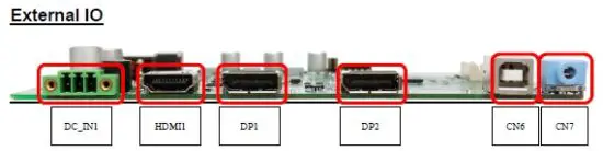
I/O and Connectors
Figure 1: Jumpers and Connectors Location
 Connecting Input Power (24V DC-in)
To connect to power, follow these steps:
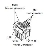
- Verify that the power cable is not energized.
- Loosen the screw clamps on the mating power connector.
- Strip the insulation from the power cables.
- Secure the power cable to the mating connector, noting polarity, and tighten the screw clamps. The torque for the attaching screws is 0.3 Nm (2.26 in-lb).
- Apply dc power to the unit. During normal startup and operation, the LED status indicator displays as follows:
• Solid amber while the RXi – Industrial Display unit is starting up
• Solid green during normal operation - Once power is applied, the unit begins initializing. The first thing to display is the splash screen.
Be sure to connect a DC power cord to this 3-pin power connector. Using a voltage out of the range may fail to boot the system or cause damage to the system board.
DC_IN1
(3.5mm Pitch 1×3 Pin Connector), DC24V power input connector
| Pin # | Power Input |
| Pin1 | DC+24V |
| Pin2 | Ground |
| Pin3 | FG |
HDMI (HDMI Input)
(HDMI Connector), High Definition Multimedia Interface connector, provides high-quality video and audio input.
Figure 2: HDMI Layout
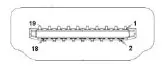
| Signal Name | Pin# | Pin# | Signal Name |
| DATA2+ | 1 | 2 | DATA2 Shield |
| DATA2- | 3 | 4 | DATA1+ |
| DATA1 Shield | 5 | 6 | DATA1- |
| DATA0+ | 7 | 8 | DATA0 Shield |
| DATA0- | 9 | 10 | CLK+ |
| HDMI CAB DET | 11 | 12 | CLK- |
| NC | 13 | 14 | NC |
| HDMI SCL | 15 | 16 | HDMI SDA |
| GND | 17 | 18 | HDMI 5V |
| HDMI HPD | 19 |
DP1 (Display Port Input)
(Display Port Connector), Display Port Interface connector, provide high-quality video and audio input.
| Signal Name | Pin# | Pin# | Signal Name |
| LANE3- | 1 | 2 | GND |
| LANE3+ | 3 | 4 | LANE2- |
| GND | 5 | 6 | LANE2+ |
| LANE1- | 7 | 8 | GND |
| LANE1+ | 9 | 10 | LANE0- |
| GND | 11 | 12 | LANE0+ |
| GND | 13 | 14 | GND |
| AUX_CHP | 15 | 16 | DP CAB DET |
| AUX_CHN | 17 | 18 | DP HPD |
| RETURN | 19 | 20 | DP 3.3V |
DP2 (Display Port Output)
(Display Port Connector), Display Port Interface connector, provide high-quality video and audio output.
| Signal Name | Pin# | Pin# | Signal Name |
| LANE0+ | 1 | 2 | GND |
| LANE0- | 3 | 4 | LANE1+ |
| GND | 5 | 6 | LANE1- |
| LANE2+ | 7 | 8 | GND |
| LANE2- | 9 | 10 | LANE3+ |
| GND | 11 | 12 | LANE3- |
| GND | 13 | 14 | GND |
| AUX_CHP | 15 | 16 | GND |
| AUX_CHN | 17 | 18 | DP HPD |
| RETURN | 19 | 20 | DP 3.3V |
CN6 (USB 2.0)
(2.0mm 1×9 Pin wafer connector), For external USB2.0 signal.
Figure 3: USB 2.0
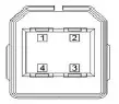
| Pin # | Signal Name |
| 1 | USB 5V |
| 2 | USB- |
| 3 | USB+ |
| 4 | GND |
CN7 (Line Out)
(Diameter 3.5mm Jack), Line Out audio port. Line Out can be connected to headphones, speakers, or an amplifier.
Figure 4: Line Out

LED Indicators
Operation Status LEDs (Screen)
All RXi Industrial Displays have a tri-color LED built into the screen that provides a visual indication of the operation status.
| LED State | System State |
| Amber, Solid | Operating system starting |
| Green, Solid | Normal operating state |
| Green, Blinking | Backlight off |
| Red, Blinking | Backlight failure |
| Off | Power not applied to the unit |
OSD
AD Board OSD Functions
Figure 5: AD Board OSD Functions Legend
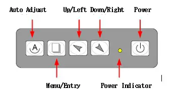
![]() Power switch: To turn ON or OFF the power
Power switch: To turn ON or OFF the power![]() Shift the icon to the left side or shift it up
Shift the icon to the left side or shift it up![]() Shift the icon to the right side or shift it down
Shift the icon to the right side or shift it down![]() Menu: To enter the OSD menu for related icons and item
Menu: To enter the OSD menu for related icons and item![]() Auto Button: One-touch auto adjustment
Auto Button: One-touch auto adjustment
Enter Burn-in Mode
Before entering the burn-in mode, first, disconnect the AC power cord, then press and hold the ![]()
![]() buttons, then release after the AC power cord is connected and the “RGB” appears on the top left corner of your screen. Now it can be put into the burn-in mode for changing colors.
buttons, then release after the AC power cord is connected and the “RGB” appears on the top left corner of your screen. Now it can be put into the burn-in mode for changing colors.
Exit Burn-in Mode
Before exiting burn-in mode, please first disconnect the AC power cord, then press the![]() button (If for any reason this button is non-functional, press and hold the
button (If for any reason this button is non-functional, press and hold the![]() button) until the AC power cord is connected. Do not release the button until the AC power cord is connected again and the wording of “RGB” appears on the top left corner of your screen, then wait for 3 seconds. If there is no input plugged into the unit, the “CABLE NOT CONNECTED” message will denote that it has successfully left burn-in mode.
button) until the AC power cord is connected. Do not release the button until the AC power cord is connected again and the wording of “RGB” appears on the top left corner of your screen, then wait for 3 seconds. If there is no input plugged into the unit, the “CABLE NOT CONNECTED” message will denote that it has successfully left burn-in mode.
If unable to exit Burn-in Mode
If the RGB is still on the top left corner of the screen, press ![]() to enter Miscellaneously and choose Reset, and then select Yes, and press
to enter Miscellaneously and choose Reset, and then select Yes, and press![]() . When the screen goes black, disconnect power and repeat the above steps.
. When the screen goes black, disconnect power and repeat the above steps.
If the RGB is not found, disconnect the AC power cord first, then press and hold the ![]()
![]() buttons until the AC power cord is connected, and wait for 2 to 3 seconds. When RGB appears, repeat the above steps.
buttons until the AC power cord is connected, and wait for 2 to 3 seconds. When RGB appears, repeat the above steps.
OSD Controls
OSD Keypad
To make any adjustment to the settings of the Industrial Monitor, select the following:
- Press
 (Menu) to show the OSD menu or dismiss the OSD menu.
 - Select the icon that you wish to adjust with the (
 /
/ or +/-) key in the menu.
 - Press (Menu) and then choose the item with the (/ or +/-) key.
- Press (Menu) and then adjust the quality with the ( /or +/-) key.
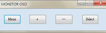
Virtual OSD Keypad
Figure 6: Virtual OSD Keyboard
Picture
Figure 7: Picture Menu Options
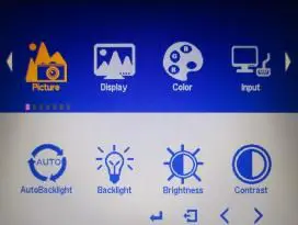
| Menu Items | Descriptions |
| AutoBacklight | Adjusts the brightness of the screen based on the brightness level of the video in use |
| Backlight | Adjusts the brightness of the display |
| Brightness | Adjusts the colors levels to simulate brightness |
| Contrast | Adjusts the scale factor (gain) to the red, green, and blue signals |
| Sharpness | Adjusts the clarity of a display’s picture or text |
Display
Figure 8: Display Menu Options
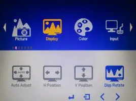
| Menu Items | Descriptions |
| AutoAdjust | The screen will calibrate the display to show the best screen orientation and position |
| H Position | Moves the screen left or right (horizontally) |
| V Position | Moves the screen up or down (vertically) |
| Disp Rotate | Rotates the display orientation (landscape/portrait) |
Color
Figure 9: Color Menu Options
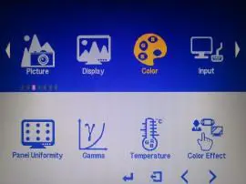
| Menu Items | Descriptions |
| Panel Uniformity | Adjusts color consistency across the screen |
| Gamma | Adjusts gamma value |
| Temperature | Adjusts temperature value |
| Color Effect | Adjusts color effect |
Input
Figure 10: Input Menu Options
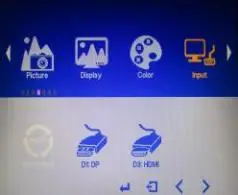
| Menu Items | Descriptions |
| Auto Select | Automatically displays input from whichever ports are supplying media |
| DP | Manually displays input from DisplayPort port |
| HDMI | Manually displays input from HDMI port |
Audio
Figure 11: Audio Menu Options

| Menu Items | Descriptions |
| Volume | Increases or decreases the volume level |
| Mute | Toggles volume on or off |
Other
Figure 12: Other Menu Options
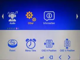
| Menu Items | Descriptions |
| Reset | It will reset the values to original/ default values. |
| Menu Time | Adjusts the time that the menu will remain on-screen after pressing the menu button. |
| OSD H Position | Moves the virtual OSD menu left or right (horizontally) |
| OSD V Position | Moves the virtual OSD menu up or down (vertically) |
Mounting Information
Panel Mount
The RXi Industrial Monitor can be panel-mounted as presented in the section entitled Mounting to Modular Display.
A Type 4, Type 4X, or IP 66 rating is achieved when mounted to the flat surface of a sufficiently rated enclosure. Please follow the instructions in the section entitled Installation Steps.
Panel Thickness: 161 to 7 Gauge (1.6 to 5mm)
Panel Cutout Dimensions
Figure 13: Panel Cutout Dimensions
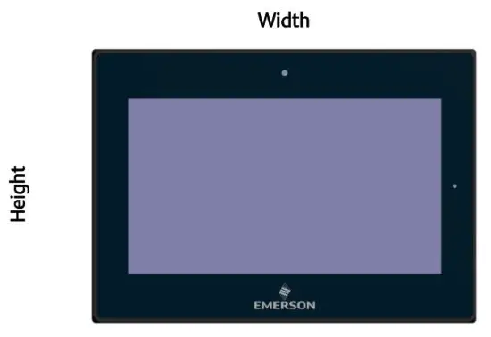
| Display Size (in) | Width (mm) | Height (mm) |
| 12 | 317 | 214.5 |
| 15 | 398 | 245.5 |
| 19 | 482 | 297 |
| 24 | 581 | 360 |
All panel cutout measurements should be within ±0.5 mm.
Values presented are width and height only.
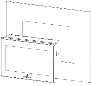
Installation Steps
- Verify that the gasket is present and properly seated in the bezel channel located on the sides of the unit. Carefully insert the unit into the mounting panel cutout.
Figure 14: Panel Install View
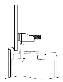
- Insert the hook of the mounting bracket into the mounting hole as displayed in the following figure.
Figure 15: Mounting Bracket Insertion
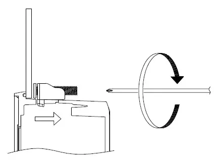
- Tighten all mounting brackets by hand until the gasket seal contacts the mounting surface uniformly.
In a cross pattern around the monitor tighten all mounting clip screws to a torque 13-13.9 in-lbs (15-16kgf-cm Make sure not to overtighten the bracket.
Figure 16: Tighten Mounting Bracket
Mounting to Modular Display
Figure 17: 12” Panel Mount
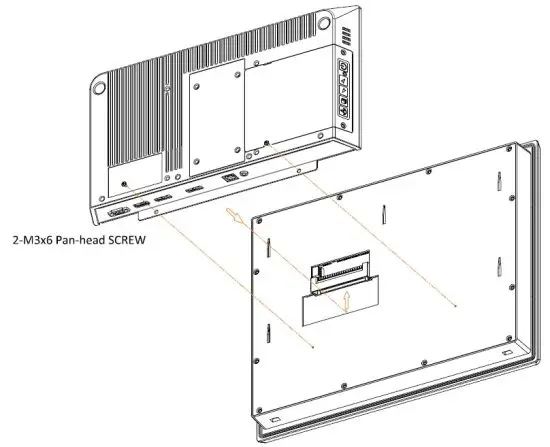
Figure 18: 15” Panel Mount
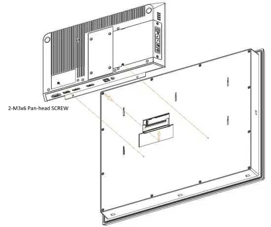
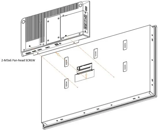
Figure 19: 19”/24” Panel Mount
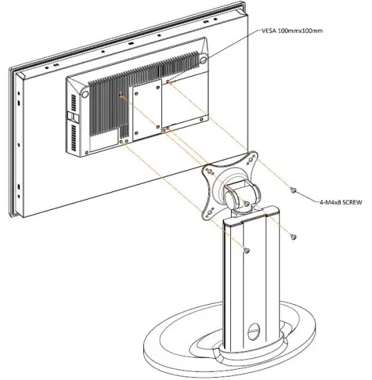
VESA Mount
The RXi Industrial Monitor can also be VESA mounted as shown in the figures below. All 7” through 24” units include VESA mount dimensions of 100mm x 100mm. All units are fastened with four M4x8 screws.
Figure 20: 10” VESA Mount
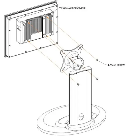
Figure 21: 12” VESA Mount
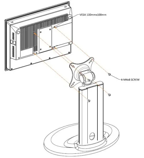
Figure 22: 15” VESA Mount
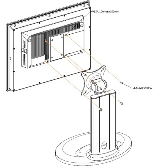
Figure 23: 19”/24” VESA Mount
Technical Support & Contact Information
Home link: http://www.emerson.com/industrial-automation-controls
Knowledge Base: https://www.emerson.com/industrial-automation-controls/support
Note: If the product is purchased through an Authorized Channel Partner, please contact the seller directly for any support.
Emerson reserves the right to modify or improve the designs or specifications of the products mentioned in this manual at any time without notice. Emerson does not assume responsibility for the selection, use or maintenance of any product.
Responsibility for proper selection, use and maintenance of any Emerson product remains solely with the purchaser.
© 2020 Emerson. All rights reserved.
Emerson Terms and Conditions of Sale are available upon request. The Emerson logo is a trademark and service mark of Emerson Electric Co. All other marks are the property of their respective owners.
![]()


