![]() The Real Made in Italy
The Real Made in Italy
Instructions 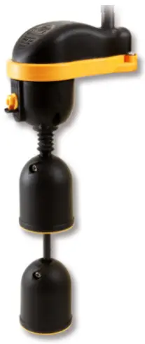
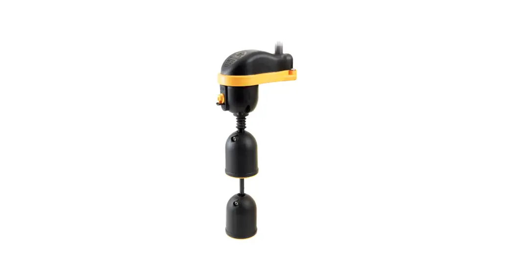
MOUSE 250Vac Float Switch
| MOUSE | Mod.01 | 250Vac 10(8)A | +50°C +122°F | 10m / 32,8ft |
| Mod.02 | 250Vac 10(10)A | +50°C +122°F | 10m / 32,8ft | |
| Mod. 04 | 250Vac 10(8)A | +50°C +122°F | 10m / 32,8ft |
 | MOUSE | HT | H07 RN8-F 3G1 | +80°C +176°F | 10m / 32,8ft |
| Drink | ACS + AD8 3X1 | +40°C +104°F | 10m / 32,8ft | ||
| Fep | FFR105OPR5F 4G0.75 | +80°C +176°F | 10m / 32,8ft | ||
| Pur | PUR – 3G0.75 | +80°C +176°F | 10m / 32,8ft |
![]()
![]() NOTES: DO NOT TAMPER WITH THE FLOAT SWITCH. THE NON RESPECT OF THE FOLLOWING POINTS WILL AUTOMATICALY CAUSE THE CANCELLATION OF THE WARANTY OF THE PRODUCT
NOTES: DO NOT TAMPER WITH THE FLOAT SWITCH. THE NON RESPECT OF THE FOLLOWING POINTS WILL AUTOMATICALY CAUSE THE CANCELLATION OF THE WARANTY OF THE PRODUCT
– Before any operation on the float remember to disconnect the power supply from the main power.
– Check that the maximum motor power does not exceed the float’s electrical values.
– In case of cable damage by the final user or installer, the float must be replaced.
– Do not make any joint on the cable of the float switch, as immersion of such joints could cause short circuits or electrical shocks.
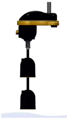
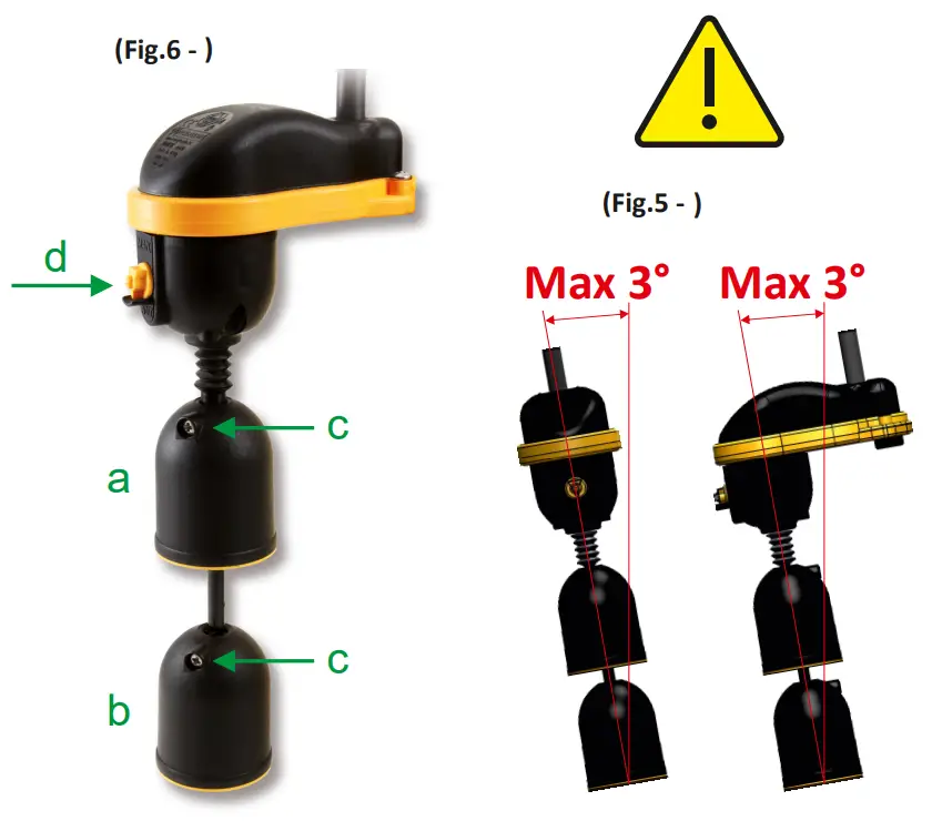
– The maximum slope for proper functioning is 3° (Fig.5)
USE:
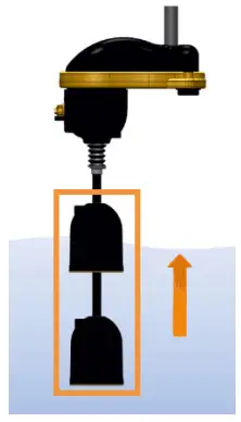
The float is a level controller that allows the user to bring the water levels at certain heights with a minimum and maximum range (Fig.6): increase or decrease the distance between the floating units of maximum (a) and minimum (b) level unscrewing the screw (c) fastened to the floating unit by means of a screwdriver with cross head and screwing with force. Make sure that the floating unit is locked securely. The water will act on the floating body when it is approximately half of this. It’s possible to set the operation of the float in automatic (ON / OFF) or manual (always ON) via the manual switch on the head of the float (d).
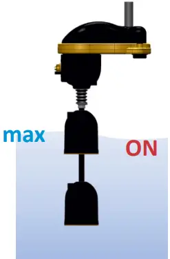
| The tank fills | The water reaches the max level. and it raises the whole floating body |
 |  |
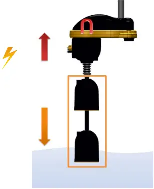
| High level starts the pump and the tank drains | The water reaches the minimum level and the weight of the floating body disengages the magnet |
 |  |
| Low level stops the pump | 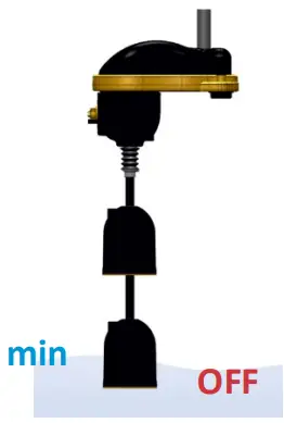 |
TECHNICAL FEATURES:
– Protection Grade: IP68
– Features of automatic action: 1B (micro-disconnections in operation)
– Pollution Degree: 2
TERMINAL CONNECTIONS:
The upstream circuit must protect the electric wires from the overcurrent.
WARNING: lack of proteconti shall null and void the warrany in the event the float breaks
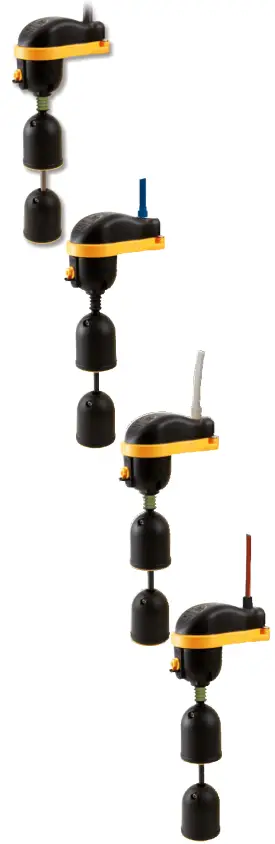
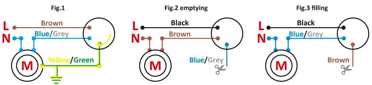
– .Mod.01: single function – only emptying or only filling (Fig.1). The grounding wire is always yellow and green.
– Mod.02 – Mod.03 double function (the fitier can choose the emptying Fig.2 or filling Fig.3 when installing):
Emptying: (Fig.2) when black and brown wires are used, the circuit opens when float is down and closes when the float is up. Note: the blue/grey wire must be insulated.
Filling: (Fig.3) when black and blue/grey wires are used, the circuit closes when float is down and opens when the float is up. Note: the brown wire must be insulated.
EC DECLARATION OF CONFORMITY
This is to declare that the product complies with the following Harmonized Standards and Directives
| Directives | Harmonized standards | |
| Low voltage Directive | 2014/35/EU | EN 55014-1; EN 60730-1; EN 60730-2-15; EN 61000-3-2; EN 61000-3-3; EN 61000-4-4; EN 61000-4-5; EN 61000-4-6; EN 61000-4-8; EN 61000-4-11. |
| Electromagnetic Compatibility Directive | 2014/30/EU | |
The person authorized to compile the Technical File is Mr. Guerrino Gastaldi at TECNOPLASTIC S.r.l.

![]() TECNOPLASTIC S.r.l. Via Calabria, 3-5 – 35020 – Saonara – Padova – ITALY
TECNOPLASTIC S.r.l. Via Calabria, 3-5 – 35020 – Saonara – Padova – ITALY
Tel: +39 049 8790775 – Fax: +39 049 644773 – www.tecnoplastic.com
REV. January 2022 www.tuv.com