 USER AND MAINTENANCE BOOK
 USER AND MAINTENANCE BOOK
![]()

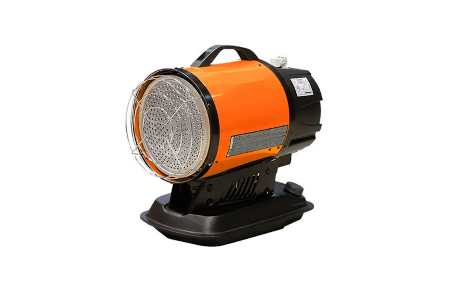
FARM FUEL
CONTROL BOARD
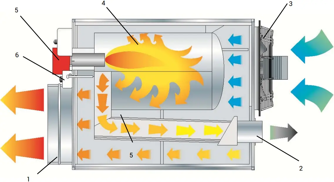
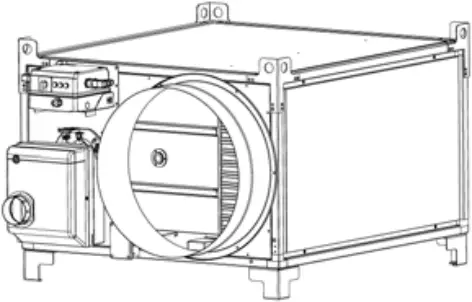
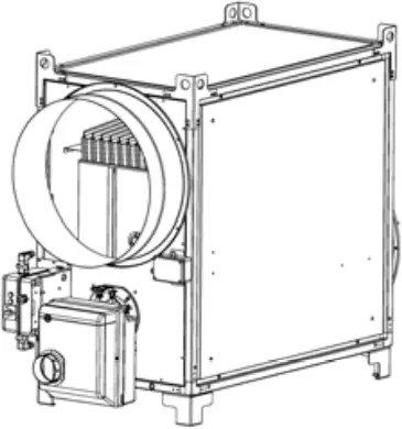
1 HOT AIR OUTFLOW 4 COMBUSTION CHAMBER
2 CHIMNEY 5 BURNER
3 COOLING FAN 6 THERMOSTATS F + L1+ L2 BOX
CONTROL PANEL
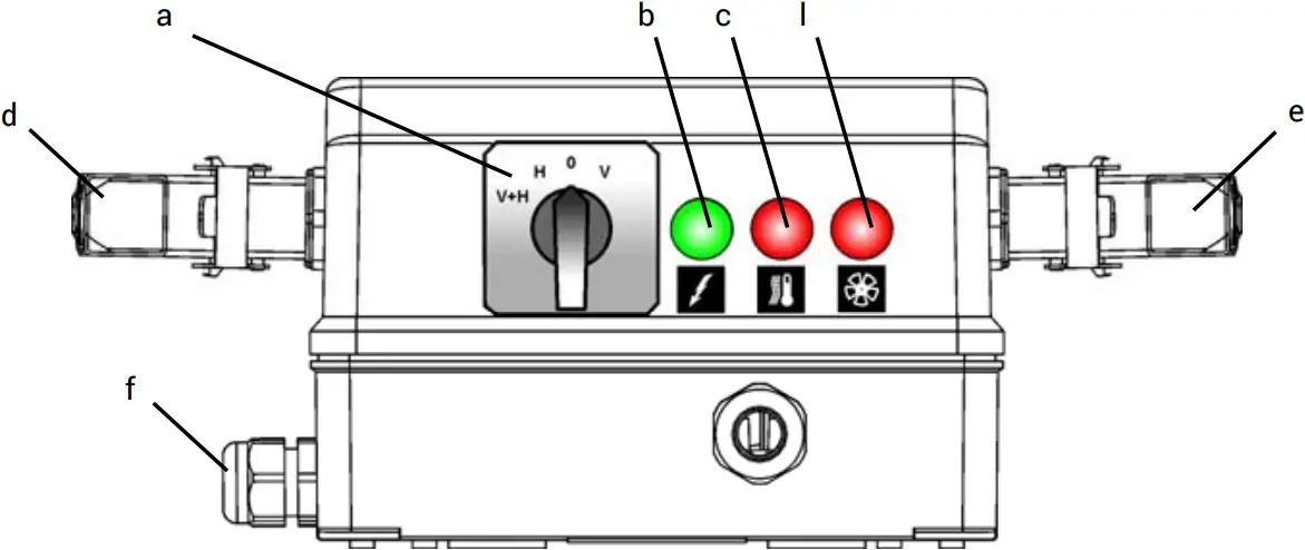
a HEATING-VENTILATION SWITCH
b VOLTAGE LAMP
c OVERHEAT THERMOSTATS CONTROL LAMP, L1, L2
d ROOM THERMOSTAT PLUG
e SOCKET FOR THERMOSTATS F + L1+ L2 BOX
f CABLE CLAMP FOR POWER CABLE
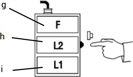
g FAN THERMOSTAT, F
8 OVERHEAT SAFETY THERMOSTAT, L1
i LIMIT THERMOSTAT WITH MANUAL RESTART, L2
l FAN BLOCK LAMP (for 3-phase models only)
IMPORTANT
Before using the space heater, carefully read all of the instructions and follow them scrupulously. The manufacturer cannot be held responsible for damage to persons and/or property caused by improper use of the equipment.
This instruction manual is an integral part of the equipment and must therefore be stored carefully and passed on with the unit in the event of a change of ownership.
1. DESCRIPTION
The space heaters described in this manual are designed to heat medium or large-size rooms requiring a fixed heating system and, in particular, to heat greenhouses and/or rooms for breeding animals. The air required for combustion is sucked directly by the burner (6) installed on the heater, and can be supplied:
- from the outside by using the flexible connection tube (available as an accessory), which avoids consuming oxygen in the room to be heated, or
- from inside the room to be heated. In this case, the room must be well ventilated to guarantee sufficient exchange of air.
The flow of hot air is moved by the high-efficiency fan (4): air is heated by the thermal energy generated during la combustion and heat from the smoke is transmitted to the fresh air through the metal walls of the sealed combustion chamber and the heat exchanger.
After the combustion products are cooled, they are conveyed to a discharge duct and eliminated through a chimney or flue large enough to guarantee their removal.
The space heaters can work with burners having ON-OFF work modes and can run on diesel fuel.
Warning Only burners approved by the manufacturer and listed in the “TECHNICAL SPECIFICATION TABLE” can be used. The heater’s certification and warranty will lapse if the burner is replaced with a non-original model, even if it has similar specifications.
All of the space heaters are fit with an electronic device that controls the flame and with:
- safety devices (safety thermostat with manual reset, flame control, air pressure switch) that trip in case of serious malfunctions and cause a safety stop. In this case the heater stops, button (d) lights with a steady red light (Stop Light) and the heater can resume operation only after the cause of the stop has been identified and eliminated;
- control devices (fan thermostat, burner thermostat, voltage control, gas pressure switch) that trip in case of minor operating faults or supply faults, causing temporary stop of the space heater. In this case, the heater will restart automatically when the required condition is restored.
The section “TROUBLESHOOTING” describes all possible operating faults and their possible remedies.
2. CONDITIONS OF SUPPLY
Space heaters can be supplied:
- fully assembled and packaged, ready for installation, or
- disassembled into main parts or groups to be assembled following separately supplied assembly instructions. In this case, the following are provided:
• Central machine body
• Electrical panel group + thermostat unit
• Motor-fan group
• Diesel burner
• Group assembly manual
• Any accessories requested (flue pipes, air distribution pipes etc.)
WarningPrior to installation, burner adjustment and ignition, the space heater should be assembled in full.
All assembly operations should only be performed by professionally qualified personnel only.
WarningUpon completing assembly, the identification labels provided in the following packaging:
- electrical panel unit
- motor-fan unit
- diesel burner
should be applied both on the space heater’s serial number label and on the declaration of assembly and installation on the penultimate page of this manual.
The following are also supplied:
- use and maintenance manuals for
• space heater
• burner - manuals with drawings and replacement part lists:
• space heater
• burner
• electrical panel
• motor-fan unit
WarningAll documents provided constitute an integral part of the unit.
The documents should therefore be looked after with care and supplied with the unit in the event of a change in ownership.
Parts are to be transported and moved using either a manual or automatic forklift truck with sufficient load capacity.
WarningNever try to lift the heater manually. Doing so could cause serious physical injury.
3. GENERAL ADVICE
The space heater must be installed, adjusted, and used in conformity to national and local laws and regulations for its operation.
General guidelines:
- Follow the instructions in this booklet very carefully;
- The heater is not installed in an area where there is a high risk of fire or explosions;
- Keep inflammable material at a safe distance from the heater (minimum 3 metres);
- Check that there is no overheating of walls, ceilings or floors made of inflammable materials,
- All precautions have been taken to prevent fires;
- The room being heated must be sufficiently ventilated so that the heater has enough air to function properly;
- The heater must be near a chimney or chimney flue and an electrical panel conforming to declared specifications;
- Check the heater before switching it on and at regular intervals during its use;
- After use, make sure the disconnecting switch is off.
When using any type of space heater it is obligatory:
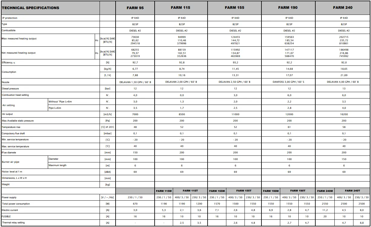
- not to exceed the maximum heat output level of the furnace (“TECHNICAL SPECIFICATION TABLE”);
- make sure that the air flow is not below the rated level; check that there are no obstacles or obstructions to the air suction and/or delivery ducts, such as sheets or covers on the equipment, walls or large objects near the heater.
WarningThis unit may not be used by persons (including children) with reduced physical, sensorial or mental capacities or with limited experience and familiarity unless they are under supervision or instructed on how to use the unit by the person responsible for its safety.
4. INSTALLATION INSTRUCTIONS
WarningAll of the operations described in this section must be performed by professionally qualified personnel only.
4.1. INSTALLATION ON FLOOR OR CEILING
The space heater may be installed:
- on the floor in a stable position
• horizontally
• or vertically
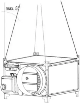
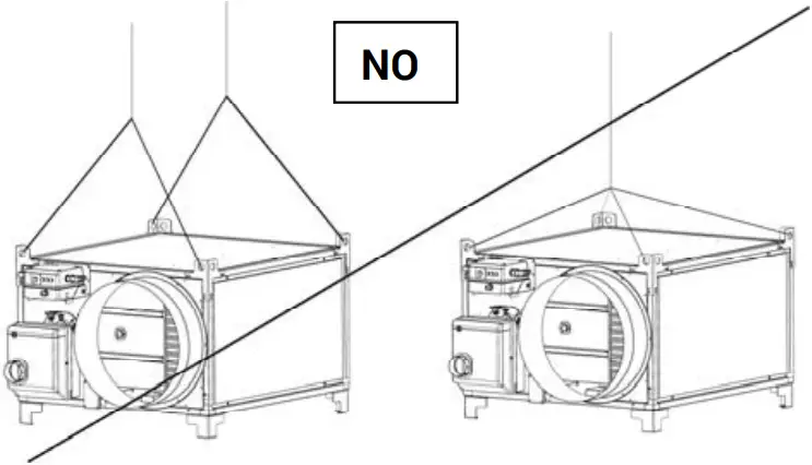
• or suspended by hooking it to the ceiling using cables and/or chains of an appropriate size and length secured to the four suspension points.
WarningMake sure that the ropes and/or chains form an angle not more than 5° with vertical to the ceiling, that the ropes do not cross, and that a different rope is used for each hook.
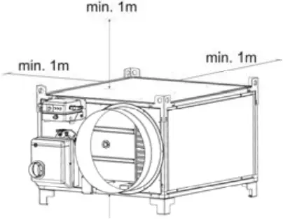
The minimum distance from surrounding walls, floor and/or ceiling must always be at least 1 metre.
4.2. POWER CONNECTIONS
WarningThe power line must be earthed and fitted with a residual current circuit breaker.
The power cable must be connected to a panel fitted with a cut-out.
Before switching on the heater and, therefore, before plugging it into the electrical power supply, check that the power supply specifications are the same as those stated on the identification plate.
WarningThe heater is fitted with a temporary power cable, used for the working test..
WarningThe provisional power cable is to be removed and replaced with an H07RN-F type cable with appropriate sectioning, to be determined in accordance with the machine’s electrical power absorption (indicated in the technical characteristics table) and in accordance with the cable length.
The cable must be stripped, leaving the earth lead at least 2 cm longer.
WarningThree-phase models are provided with thermal motor protection and the thermal relay must be adjusted to the value listed in the “TECHNICAL CHARACTERISTICS TABLE”.
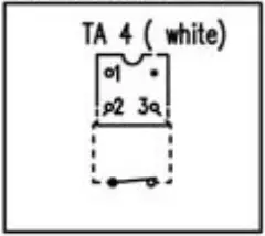
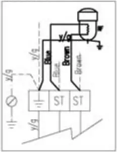
Any room thermostat or other accessories (such as a timer) are connected to the system by connecting the electrical cable to the thermostat plug (c):
- Take the plug (c) out of the electrical panel, open the plug and remove the jumper between terminals 2 and 3.
- Connect the thermostat electrical cable to terminals 2 and 3 of the thermostat plug (c).
- Close the plug again and plug it back into the panel.
WarningNever attempt to switch the heater on or off by connecting the room thermostat (or other control devices) to the electrical power line.
The installation and connection of all the other accessories are described in the specific instructions included with each accessory, together with operating instructions.
The electrical diagram shown in this manual refers to the electrical connection only.
4.3. CONNECTION TO HOT AIR DELIVERY DUCTS
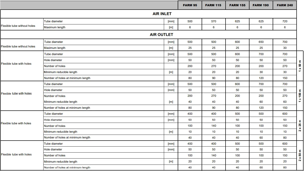
The space heater is set to operate with direct distribution of air. Nevertheless, it can be connected to appropriately sized air distribution channels, if required, with maximum diameter and length as shown in the “TABLE OF TECHNICAL CHARACTERISTICS.”
WarningBefore starting the heater, check that the direction of rotation of the fan matches the direction shown on the fan itself.
The air distribution channels can be connected by using the various available accessories, placing the connections on the front, side, or top as required.
4.4. CONNECTION TO FUEL SUPPLY
WarningThe heater must be installed, set up, and used in compliance with all applicable regulations.
Connection to the diesel supply pipe can be made by connecting the fuel tank to the burner pump:
- directly, i.e., by using the burner’s diesel pump, in conformity to the dimensions and lengths specified in the burner instruction manual attached hereto.
- indirectly, i.e., by using an auxiliary return diesel pump. In this case, contact a Customer Service Centre to ensure correct sizing of the fuel system.
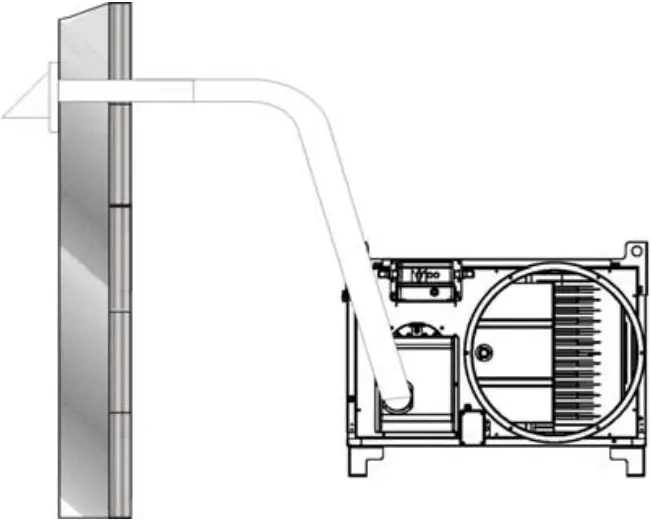
4.5. CONNECTING BURNER TO “SNORKEL” DEVICE AND SETTING COMBUSTION AIR
The burner air intake (3) can be connected outside the room to be heated in order to suck in clean air and avoid depleting the oxygen in the room.
The connection pipe must be rigid to prevent shrinking due to air intake depression. It must have a minimum diameter of 100 mm and maximum length of 6 metres.
WarningIf the hose is too long, remove the excess without leaving loops and/or curves which may hinder air suction.
The end part of the suction hose should be connected to a wall accessory with safety grille to prevent small animals and/or debris from entering the hose.
WarningBurner air should be adjusted in accordance with the indications listed in the “TECHNICAL CHARACTERISTICS TABLE”.
4.6. CONNECTION TO EXHAUST DUCT
Exhaust ducts must be in steel and conform to EN 1443.
Efficient combustion and trouble-free working of the burner depend on efficient flue draft.
The unit must be connected to the chimney flue in compliance with current legal regulations and in line with the following guidelines:
- The path of the flue pipe smoke should be as short as possible and should slant upwards (minimum height 1 m);
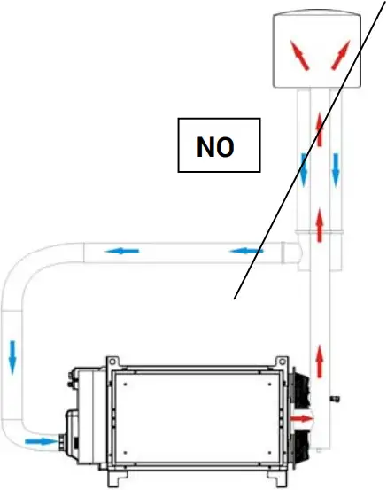
- There should be no sharp curves in the pipes, and the diameter of the pipes must never be reduced;
- there must always be a wind deflector to prevent the entrance of rain and to prevent smoke from being blocked by the wind;
- flue draft must at least equal the level in the Technical Specifications.
- every heater must have its own chimney;
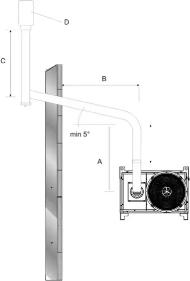
The following diagrams show possible flue positions:
A) Minimum 1 m
B) As short as possible
C) Minimum 1 m
D) Chimney draught H shape
WarningCoaxial flue pipes must not under any circumstances be used for flue gas exhaust and burner air suction on these units: functioning may be irreparably compromised.
4.7. FIRST START-UP AND COMBUSTION ADJUSTMENT
WarningThe first start-up should always be carried out by a specialised technician checking the correctness of the combustion parameters.
WarningThe burner settings are pre-set at the factory and may not comply with those required, therefore, the settings need to be checked and, where necessary, corrected.
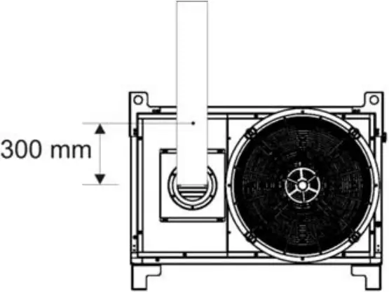
The adjustment values (burner diesel pressure, combustion head position, air adjustment) for each of the burners approved for these units are indicated in the “TECHNICAL CHARACTERISTICS TABLE”. The probe used to periodically check combustion and flue smoke temperatures is to be inserted as indicated:
Combustion is clean and stable when combustion values are as follows:
Bacharach index: 0 (white)
CO2: 11 ÷ 12,5 %
Oxygen (O2): 4,5 ÷ 6 %
COmax: 500 ppm
You may have to change the burner settings due to the fuel used and/or installation conditions (high altitude, air suction pipe with or without Snorkel, etc.) if combustion parameters are not correct.
When inspection tests are completed, the hole drilled for the probe must be sealed with a material that is resistant to high temperatures and that ensures the tube remains airtight.
WarningUpon completing the aforementioned operations, the declaration of assembly and installation on the penultimate page of this manual is to be completed in full and signed.
5. OPERATING INSTRUCTIONS
5.1. START
To start the heater:
- Make sure the switch (a) is set to “0”;
- Supply electrical power to the space heater by pulling up the disconnecting switch on the electric power panel: the green lamp (b) will light up indicating that power is being supplied to the panel;
- Press the switch (a) in the H or H+V position: the burner will begin the start-up and pre-wash cycle, after which the flame will ignite; after the combustion chamber has been heating for a few minutes, the main fan will start up;
WarningThe fan runs continuously in H+V mode, even when the desired room temperature has been reached, and the burner turns off.
WarningIn H mode, the fan only runs when the combustion chamber is sufficiently hot. Therefore, when the desired room temperature has been reached, the burner turns off and the fan keeps running only until the combustion chamber has cooled completely.
- If the heater does not work during the start cycle or work cycle, consult “TROUBLESHOOTING” to find the cause of the malfunction.
WarningIn case of safety stop, you have to push the reset button (d) for 3 seconds to restart the heater.
WarningNEVER do more than two restarts in a row: unburned fuel can accumulate in the combustion chamber and suddenly flare up at the next restart.
5.2. STOP
To stop the heater turn and press switch (a) to “0” position or, if the heater is in automatic mode, by setting the room thermostat to a lower temperature: the burner shuts off and lamp (f) goes out. The fan keeps running until the combustion chamber has cooled completely.
WarningNever stop the heater by simply turning off the disconnecting switch on the panel.
The electrical supply must be disconnected ONLY when the fan has come to a complete stop.
5.3. VENTILATION
To run the heater only in continuous ventilation mode, turn switch (a) to the position with the symbol V.
6. MAINTENANCE
WarningAll of the operations described in this section must be performed by professionally qualified personnel only.
The following procedures must be done at regular intervals to ensure efficient operation of the heater. Make sure you have detached the electrical power line from the heater before starting any work.
WarningBefore doing any maintenance:
- Stop the heater as indicated in the “STOP” paragraph;
- Switch off the power supply by means of the cut-off on the electrical panel;
- Wait until the heater cools.
Procedure | Periodic maintenance | |||
| Every day | Every week | Every six months | Every year | |
| Check heater | X | |||
| Check gas supply line | X | |||
| Clean exterior of heater | X | |||
| Clean motor and fan | X | |||
| Check gas supply pressure | X | |||
| Check electrical connections | X | |||
| Check and test burner | X | |||
| Check thermostats | X | |||
| Clean interior of heater | X | |||
| Inspect and clean combustion chamber | X | |||
6.1. CHECKING THE HEATER AND THE DIESEL SUPPLY LINE
Perform the following checks:
- Make sure the heater is not installed where there may be a risk of fire or explosion
- Make sure that flammable materials are kept a safe distance away
- If you find diesel leaks:
• Close the diesel stopcock
• Find and repair the source of the diesel leak - Do not use the heater if any removed panels have not been remounted
- Make sure the room to be heated is sufficiently ventilated
- Make sure that the air intake and outlet are completely unobstructed
- Make sure that the heater is not covered by any sheets or covers
- Check that the heater is in a fixed and stable position;
- Make sure the heater is constantly monitored during operation and checked before being started;
6.2 CLEANING THE EXTERIOR OF THE HEATER
To ensure efficient operation, clean the following parts:
- Burner:
• Remove all external dirt and debris
• Make sure the air inlet is not obstructed. - Pipes, connectors and joints:
• Clean with a cloth. - External body:
• Clean with a cloth. - Air inlet/outlet:
• Remove all dirt and debris
• Make sure the air inlet is not obstructed.
6.3 Cleaning the motor and the fan
Clean the fan blades and the motor as follows:
- Remove the fan group fixing screws and then remove the fan group.
- Clean the motor with compressed air.
- Clean the fan blades with a hard brush.
- Reinstall the fan group.
6.4 CHECKING THE ELECTRICAL CONNECTIONS
After detaching the power cable, check all electrical connections as follows:
- Make sure that all connections are complete and tight.
- If there are traces of dirt or corrosion, clean or replace the connections if necessary.
- Replace any damaged wires or connectors if necessary.
6.5 CHECKING AND TESTING THE BURNER
To reach the burner:
- Remove the burner fixing screw.
- Remove the burner and follow the checking and cleaning instructions in the burner manual.
- Reinstall the burner.
- Run the procedures described in paragraphs 4.7 and 4.8 to measure combustion parameters and check that combustion is stable and clean.
6.6 CHECKING THE THERMOSTATS
Inspect the thermostat burner as follows:
- Remove any air outlet connection ducts
- Find the thermostats fixed to the internal panel of the space heater.
- Clean with a dry cloth, taking care not to cut or bend the capillary tube.
6.7 CLEANING THE INTERIOR OF THE HEATER
For thorough cleaning, the heater can be cleaned and washed inside and outside with water. It is however necessary to ensure that:
- the electrical cable is disconnected and unplugged from the socket
- completely close all access panels
- do not use water jets at a pressure exceeding 70 bar at a distance less than 30 cm
- completely dry all parts before reconnecting the electrical cable.
6.8 CLEANING THE COMBUSTION CHAMBER
To maintain the burner’s high efficiency and prolong its life, the procedure described in this paragraph must be done at least once at the end of the work season or more frequently if there is an excessive build-up of soot. Excessive soot may be caused by poor chimney draught, poor fuel quality, poor regulation of the burner, or more or less frequent alternation of burner starts and stops.
Pay attention during operation: pulsations at start may be due to excessive amounts of soot..
To access the heat exchanger (1), take off the rear panel (3), remove the smoke box inspection panel (2), and then remove baffle plates (7).
To access the combustion chamber (4) remove the burner (5).
Clean with compressed air or, if necessary, with a metal brush to remove any deposited soot and combustion residues.
WarningAfter any technical work, always check that the heater works correctly.
7. TROUBLESHOOTING
In the event of serious anomalies, various safety devices are able to block the machine’s operation and signal the same:
- on the electrical panel
 the blocking signal following intervention by the safety thermostat: the reset button is located on the thermostat F+L1+L2 box.
 (for three-phase models only) the blocking signal following intervention by the motor thermal protection: the reset button is located inside the electrical panel.
 - on the burner
 the blocking signal following intervention by the burner’s flame control box.
WarningNEVER do more than two restarts in a row: unburned fuel can accumulate in the combustion chamber and suddenly flare up at the next restart.
If the heater is still not working properly, please contact your nearest dealer or authorized Service Centre.
FAULT | CAUSE | REMEDY |
|
|
|
|
|
|
|
| |
|
| |
|
|
|
|
| |
|
|
|
| The heater does not work: the lamp |
|
|
|
|
|
|
|
|
|
| |
|
|
|
230V, 1 ~, 50Hz
220V, 1 ~, 60Hz
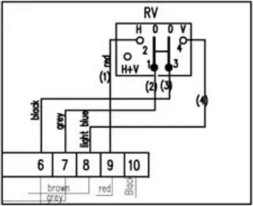
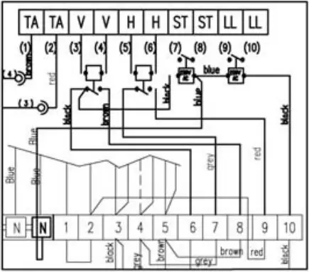
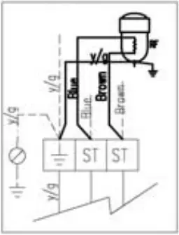
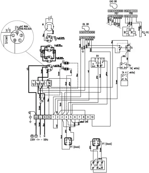
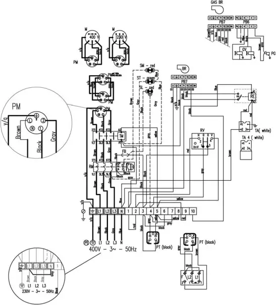
WIRING DIAGRAM
REMOTE CONTROL 3mt: OPTIONAL
REMOTE CONTROL BY PC: OPTIONAL
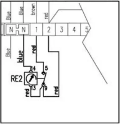
OPTIONAL – delay starting relay

OPTIONAL
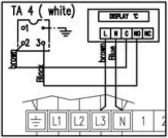
Room thermostat: OPTIONAL
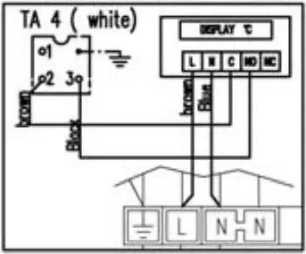
Electronic thermostat: OPTIONAL
M FAN MOTOR
F FAN THERMOSTAT
FB FUSE
ST POWER LAMP
L2 LIMIT THERMOSTAT WITH MANUAL RESTART
RV HEATING-STOP-VENTILATION SWITCH
SL OVERHEAT THERMOSTATS CONTROL LAMP
L1 BURNER THERMOSTAT
TA ROOM THERMOSTAT PLUG
RE2 DELAYED IGNITION RELAY
R ANTI-CONDENSATION RESISTANCE
TM FANS TELE-CONTACTOR
RM FANS THERMAL RELAY
ST POWER LAMP
SM FAN STOP LAMP
BR BURNER
PB7 BURNER PLUG
RV HEATING-STOP-VENTILATION SWITCH
230/400V, 3 ~, 50Hz
220/400V, 3 ~, 60Hz
REMOTE CONTROL 3mt: OPTIONAL

REMOTE CONTROL BY PC: OPTIONAL

OPTIONAL – delay starting relay
OPTIONAL
Room thermostat: OPTIONAL

Electronic thermostat: OPTIONAL
M FAN MOTOR
F FAN THERMOSTAT
FB FUSE
ST POWER LAMP
L2 LIMIT THERMOSTAT WITH MANUAL RESTART
RV HEATING-STOP-VENTILATION SWITCH
SL OVERHEAT THERMOSTATS CONTROL LAMP
L1 BURNER THERMOSTAT
TA ROOM THERMOSTAT PLUG
RE2 DELAYED IGNITION RELAY
R ANTI-CONDENSATION RESISTANCE
TM FANS TELE-CONTACTOR
RM FANS THERMAL RELAY
ST POWER LAMP
SM FAN STOP LAMP
BR BURNER
PB7 BURNER PLUG
RV HEATING-STOP-VENTILATION SWITCH
DECLARATION OF ASSEMBLY AND INSTALLATION
![]() The space heater, Model / Serial number
The space heater, Model / Serial number
Fitted with a motor-fan, electrical panel and burner
has been assembled and commissioned by:
Authorised Technical Service / Installer:
Date : __________________ Signature :
__________________
L-L 230.04-BM
L-D457.01-SO
FARM 95
| PL 05/16 | From S/N | ||
65500101 | |||
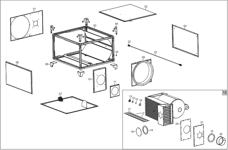
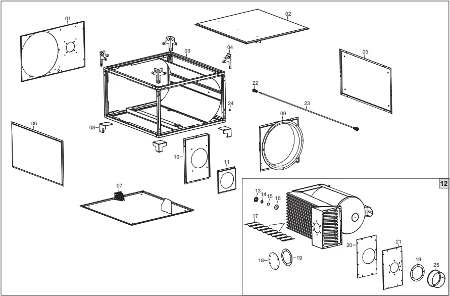
POS | P/N | LEGENDA | DESCRIPTION |
| 01 | G04309 | – | Panel |
02 | G04310 | – | Panel |
03 | G04311 | – | Frame |
04 | G04289 | – | Stirrup |
05 | G04312 | – | Panel |
06 | G04313 | – | Panel |
07 | G04314 | – | Panel |
08 | G04293 | – | Support |
09 | G04315-9005 | – | Outlet panel |
10 | G04316 | – | Panel |
11 | G04317 | – | Panel |
12 | G04318 | – | Combustion chamber |
13 | G04298 | – | Disc |
14 | T10692 | D36 x D25 | Insulating gasket |
15 | T10405 | – | Tempered glass |
16 | T10691 | D60 x D25 | Insulating gasket |
17 | G04319 | – | Turbulence-generating grid |
18 | G04320 | – | Inspection panel |
19 | T10804 | D170 x D120 | Insulating gasket |
20 | T10687 | 444x251x5 | Insulating gasket |
21 | G04321 | – | Panel |
22 | E20699 | 4P + T | Plug |
23 | E30474-1 | L = 1,5 m | Motor power cord |
24 | C30301 | Ø18 mm | Cable protection |
25 | G04322 | Ø 200 | Chimney fitting |
L-D458.01-SO
FARM 115

| PL 05/16 | From S/N | ||
65600101 | |||
POS | P/N | LEGENDA | DESCRIPTION |
01 | G04324 | – | Panel |
02 | G04325 | – | Panel |
03 | G04326 | – | Frame |
04 | G04289 | – | Stirrup |
05 | G04327 | – | Panel |
06 | G04328 | – | Panel |
07 | G04329 | – | Panel |
08 | G04293 | – | Support |
09 | G04330-9005 | – | Outlet panel |
10 | G04331 | – | Panel |
11 | G04317 | – | Panel |
12 | G04332 | – | Combustion chamber |
13 | G04298 | – | Disc |
14 | T10692 | D36 x D25 | Insulating gasket |
15 | T10405 | – | Tempered glass |
16 | T10691 | D60 x D25 | Insulating gasket |
17 | G04333 | – | Turbulence-generating grid |
18 | G04320 | – | Inspection panel |
19 | T10804 | D170 x D120 | Insulating gasket |
20 | T10687 | 444x251x5 | Insulating gasket |
21 | G04321 | – | Panel |
22 | E20699 | 4P + T | Plug |
23 | E30474-2 | L = 1,6 m | Motor power cord |
24 | C30301 | Ø18 mm | Cable protection |
25 | G04322 | Ø 200 | Chimney fitting |
L-D407.01-SO
FARM 155

| PL 05/16 | From S/N | ||
65700501 | |||
POS | P/N | LEGENDA | DESCRIPTION |
| 01 | G04286 | – | Panel |
02 | G04287 | – | Panel |
03 | G04288 | – | Frame |
04 | G04289 | – | Stirrup |
05 | G04290 | – | Panel |
06 | G04291 | – | Panel |
07 | G04292 | – | Panel |
08 | G04293 | – | Support |
09 | G04294-9005 | – | Outlet panel |
10 | G04295 | – | Panel |
11 | G04296 | – | Panel |
12 | G04323 | – | Combustion chamber |
13 | G04298 | – | Disc |
14 | T10692 | D36 x D25 | Insulating gasket |
15 | T10405 | – | Tempered glass |
16 | T10691 | D60 x D25 | Insulating gasket |
17 | G04304 | – | Turbulence-generating grid |
18 | G04306 | – | Inspection panel |
19 | T10805 | – | Seal |
20 | T10689 | 517x311x5 | Insulating gasket |
21 | G04307 | – | Panel |
22 | E20699 | 4P + T | Plug |
23 | E30474-3 | L = 1,8 m | Motor power cord |
24 | C30301 | Ø18 mm | Cable protection |
25 | G04308 | Ø 200 | Chimney fitting |
L-D459.01-SO
FARM 190
| PL 05/16 | From S/N | ||
65800101 | |||
POS | P/N | LEGENDA | DESCRIPTION |
| 01 | G04334 | – | Panel |
02 | G04335 | – | Panel |
03 | G04336 | – | Frame |
04 | G04289 | – | Stirrup |
05 | G04337 | – | Panel |
06 | G04338 | – | Panel |
07 | G04339 | – | Panel |
08 | G04293 | – | Support |
09 | G04340-9005 | – | Outlet panel |
10 | G04341 | – | Panel |
11 | G04296 | – | Panel |
12 | G04342 | – | Combustion chamber |
13 | G04298 | – | Disc |
14 | T10692 | D36 x D25 | Insulating gasket |
15 | T10405 | – | Tempered glass |
16 | T10691 | D60 x D25 | Insulating gasket |
17 | G04304 | – | Turbulence-generating grid |
18 | G04306 | – | Inspection panel |
19 | T10805 | – | Seal |
20 | T10694 | 555x311x5 | Insulating gasket |
21 | G04343 | – | Panel |
22 | E20699 | 4P + T | Plug |
23 | E30475-1 | L = 2,0 m | Motor power cord |
24 | C30301 | Ø18 mm | Cable protection |
25 | G04344 | Ø 200 | Chimney fitting |
L-D460.01-SO
FARM 240

| PL 05/16 | From S/N | ||
65900101 | |||
POS | P/N | LEGENDA | DESCRIPTION |
| 01 | G04345 | – | Panel |
02 | G04346 | – | Panel |
03 | G04347 | – | Frame |
04 | G04289 | – | Stirrup |
05 | G04348 | – | Panel |
06 | G04349 | – | Panel |
07 | G04350 | – | Panel |
08 | G04293 | – | Support |
09 | G04351-9005 | – | Outlet panel |
10 | G04352 | – | Panel |
11 | G04296 | – | Panel |
12 | G04353 | – | Combustion chamber |
13 | G04298 | – | Disc |
14 | T10692 | D36 x D25 | Insulating gasket |
15 | T10405 | – | Tempered glass |
16 | T10691 | D60 x D25 | Insulating gasket |
17 | G04354 | – | Turbulence-generating grid |
18 | G04306 | – | Inspection panel |
19 | T10805 | – | Seal |
20 | T10696 | 675x311x5 | Insulating gasket |
21 | G04355 | – | Panel |
22 | E20699 | 4P + T | Plug |
23 | E30475-2 | L = 2,3 m | Motor power cord |
24 | C30301 | Ø18 mm | Cable protection |
25 | G04344 | Ø 200 | Chimney fitting |
CARNET D’ENTRETIEN
TYPE :……………………………………………………………………….
N° DE SERIE:……………………………………………………………….
DATE | ENTRETIEN | PIECES CHANGEES | OBSERVATION | |
REGULIER | ANNUEL | |||
Dantherm S.p.A.
Via Gardesana 11, -37010-
Pastrengo (VR), ITALY
Dantherm Sp. z o.o.
ul. Magazynowa 5A,
62-023 Gadki, POLAND
Dantherm SAS
23 rue Eugene Henaff – CS 80010
69694 VENISSIEUX, Cedex, FRANCE
Dantherm LLC
ul. Transportnaya 22/2,
142802, STUPINO, Mascow region, RUSSIA
Dantherm China LTD
Unit 2B, 512 Yunchuan Rd.,
Shanghai, 201906, CHINA
Dantherm SP S.A.
C/Calabozos, 6 Poligono Industrial, 28108
Alcobendas, Madrid, SPAIN


