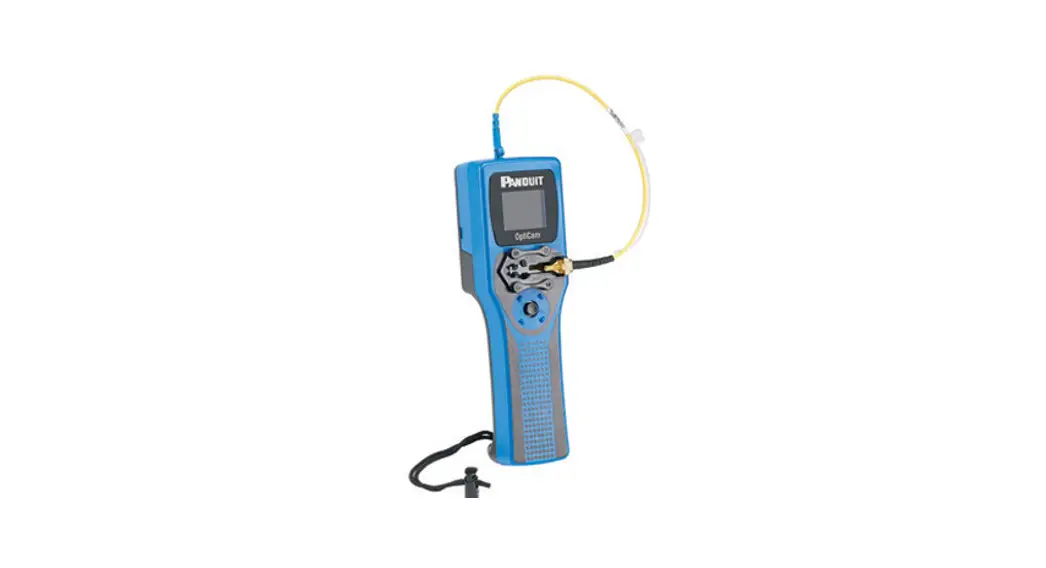
![]() OptiCam 2 Termination Tool
OptiCam 2 Termination Tool
Instruction Manual
FS132D OptiCam 2 Termination Tool

https://www.panduit.com/OptiCam2
![]() WARNING
WARNING![]()
Read and understand the instructions and safety information in this manual before operating this tool.
Failure to observe this warning can result in bodily injury.
Warning: Risk of fire. Battery can explode or leak and cause injury if installed backwards, disassembled, charged, crushed, or exposed to fire or high temperature.
![]() CAUTION
CAUTION
Caution – Use of controls or adjustments or performance of procedures other than those specified herein may result in hazardous radiation exposure. The laser is emitted from the LC connector located at the top of the tool.
- Never point the laser into the eyes of others.
- Do Not stare directly at the laser beam.
- Do Not set up tool to work at eye level or operate the tool on a reflective surface as the laser could be projected into your eyes or the eyes of others.
Viewing the laser output with certain optical instruments (for example,eye loupes, magnifiers, and microscopes) within a distance of 3.9” (99mm) may pose an eye hazard.
Remove the batteries when storing for an extended period to avoid damage to the tool should the batteries deteriorate.
TECHNICAL INFORMATION
| Recommended Use: | With available launch cords and cradles only |
| Laser Diode Type: | IEC 60825-1 Class 1 Laser product |
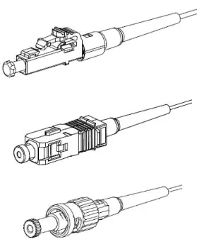
| Connectors: | Panduit LC, SC, ST, singlemode and multimode,OptiCam connectors only |
| Power Supply: | 2 size AA (type L91) 1.5volt Lithium Iron Disulfide batteries, Max Discharge: 2.5 amp continuous, included. Size AA alkaline batteries can be used at a reduced rate battery life. Tool can also be powered without batteries through the power/data (5 VDC, 1 amp max) port on the side of the tool. |
| Rated Battery Life: | Approximately 8 hours (continuous use) |
| Firmware Updates: | Use power/data port on the side of the tool to connect to PC, visit www.panduit.com for latest firmware |
| Environment | FOR INDOOR USE ONLY Max altitude 2000mPollution degree 2 |
| Operating Temperature: | 32° F to +104° F (0° C to +40° C), <93% RH, nonondensing |
| Storage Temperature: | -40° F to +158°F (-40°C to +70°C) |
| Overall Dimensions: | 2.1″ H x 2.8″ W x 9.1″ L (53mm x 71mm x 231mm) |
| Weight: | 9.0 oz (255 g) without batteries |
Tool Storage
After all connector terminations are complete, detach the launch cord from the tool by disconnecting the LC connector at the top of the tool. Detach the ferrule adapter from the cradle and put dust caps on both ends of the launch cord. Place tool, launch cord, and cradle in a protective case.
Care and Handling
- Laser tools are precision instruments, which should be handled with care.
- Avoid shock, vibrations, and extreme heat.
- Avoid dust and water that could obstruct laser.
- Keep tool dry and clean.
- Check batteries regularly to avoid deterioration.
- Remove batteries if the tool is to be stored for an extended period.
Tool Maintenance
- This tool contains no user serviceable parts.
- The laser output is not user adjustable.
- Contact Panduit Corp. for service needs.
Symbols
This symbol indicates the need for separate collection of electrical and electronic equipment waste. Separating electronic waste can halt the potential adverse effects on the environment and human health because of the hazardous substances in electrical and electronic equipment. This waste should be returned to the proper collection facility.
![]()
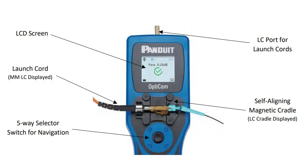
Product Overview
Start Up Guide
| Step 1: Remove battery cover on the rear of the tool nd insert the batteries (ensuring correct alignment). Tip: Always use size AA Energizer L91 1.5v Lithium Iron Disulfide batteries or similar for optimal tool performance. | 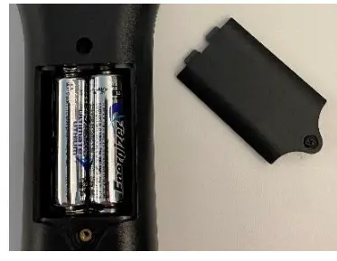 |
| Step 2: Remove the protective film cover from the camera aperture and LCD screen. |  |
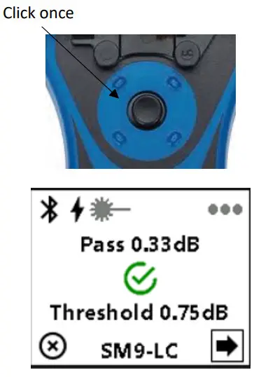
| Step 3: Power up the tool by clicking once on the center of the selector switch (do not hold the button down)Select your language of choice. | 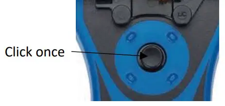 |
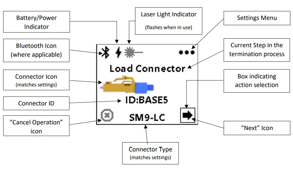
Screen Overview
(Appearance may vary depending on firmware version)
Tip: Always ensure the OptiCam® 2 Tool is on the most current version of firmware. This can be found at:
Panduit.com > Support > Download Center > Software, Firmware, Printers > OptiCam® 2 Termination Tool
https://www.panduit.com/OptiCam
Performing Terminations
| Step 1: Set up the tool by selecting the correct launch cord, cradle, and tool settings. The launch cord and cradle table is displayed below. Make sure to ‘Save’ the selections. Note: the image to the right displays the set up for a singlemode LC termination. Options may appear differently depending on firmware version on the tool. | 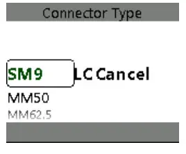 |
| Connector Type | Launch Cord Part Number | Launch Cord Color | Cradle Part Number | Cradle Color |
| LC Singlemode (e.g. FLCSSCBUY) | FOLPC-1.25SM | Yellow | FLCC2 | Black |
| LC Multimode [all grades] (e.g. FLCSMCXAQY, FLCSMC6EIY) | FOLPC-1.25MM | Orange | ||
| SC Singlemode (e.g. FSC2SCBU) | FOLPC-2.5SM | Yellow | FSCC2 | Gray |
| ST Singlemode (e.g. FST2SCBU) | FSTC2 | Gray with black components | ||
| SC Multimode [all grades] (e.g. FSC2MCXAQ, FSC2MC6EI) | FOLPC-2.5MM | Orange | FSCC2 | Gray |
| FSTC2 | Gray with black components | |||
| ST Multimode [all grades] (e.g. FST2MCXAQ, FST2MC6EI) |
Tip: When snapping the LC launch cord into the cradle it is vital to make sure the circular aperture on the metal adapter faces down, towards the tool. Failure to align the adapter properly will create difficulty with the process. Also, ensure that the metal adapter is firmly tightened onto the cord before installing onto the cradle.
Tip: When terminating ST connectors, the launch cord must be inserted directly onto the connector’s ferrule. If it is not fully pushed onto the connector, the tool may not recognize the connector in the following steps.
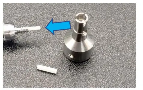
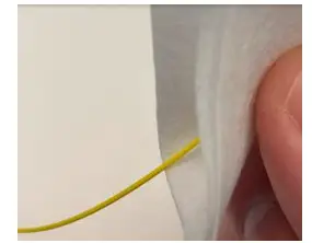
| Step 2: Clean both ends of the launch cord before loading it onto the tool. Note: Remove the adapter and alignment sleeve from the cord to properly clean the ferrule. Tip: Clean the launch cord every 50 terminations for optimal tool performance. DO NOT use pre-saturated wipes. |
|
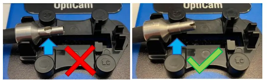
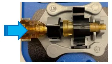
| Step 3: Clean the connector, then load the connector into the appropriate adapter and cradle. Tip: If the tube is protruding from the rear of an LC connector, it is not properly seated in the adapter. Rotate the connector slightly until it can be locked in without the insertion tube sticking out of the connector. (below) 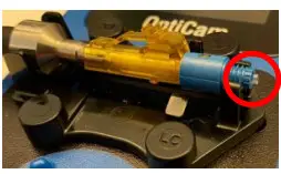 Tip: Make sure the alignment tab under the ferrule aligns with the guide on the cradle for ST terminations. (below) Tip: Make sure the alignment tab under the ferrule aligns with the guide on the cradle for ST terminations. (below)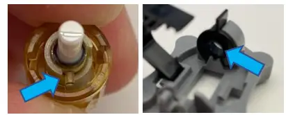 |
|
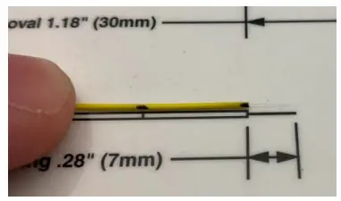
| Step 4: Slide the boot onto the cable, narrow end first, then push it back out of the way. Use the appropriate Stripping Template to make a strip mark and an insertion mark on the buffer. |
|
| Step 5: Strip the buffer in 1/8” (3mm) increments, up to the strip mark on the buffer. If the fiber breaks during this process, rotate the fiber slightly to make new marks on the buffer and start the strip process over again. | 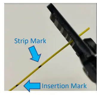 |
| Step 6: Clean the bare fiber using a dry wipe and approved cleaning solution. Note: DO NOT use pre-moistened wipes. Note: Observe appropriate fiber safety precautions. |
|
| Step 7: Cleave the bare fiber to 7mm. Tip: You can verify the cleave length using the stripping template. 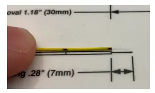 | FSPCVR: Press the metal square on the right side of the cleave tool all the way to the left until the blade locks in place.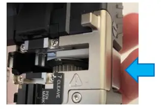 FSPCVR: Align the end of the buffer with the 7mm mark on the cleaver, then close the lid to complete the cleave process. FSPCVR: Align the end of the buffer with the 7mm mark on the cleaver, then close the lid to complete the cleave process.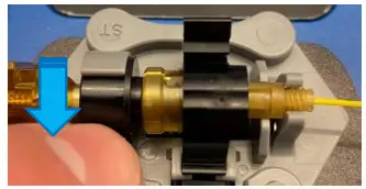 |
| Step 7: Cleave the bare fiber to 7mm. Tip: You can verify the cleave length using the stripping template. 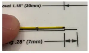 Note: Observe appropriate fiber safety precautions. Note: Observe appropriate fiber safety precautions. | FJQCVR: Align the end of the buffer with the 7mm mark on the cleaver. Gently tap the blade down onto the fiber once (and only once). Release the blade, then gently bend the the tongue on the cleaver until the fiber snaps to complete the cleave.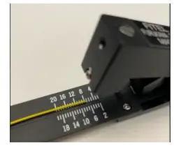 |
| Step 8: On the OptiCam® 2 tool, click the selector switch once to go from the ‘Load Connector’ screen to the ‘Background Test’ screen. Note: If the tool presents a ‘Cleaning Required’ or ‘Check Failed’ message, follow the troubleshooting steps on the tool, or watch the troubleshooting video on panduit.com. Contact Panduit’s Technical Support team if further support is needed. | 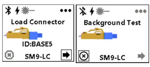 |
| Step 9: Once the screen reads ‘Insert Fiber’ begin inserting the fiber into the rear of the connector. Advance the fiber until the insertion mark lines up at the rear of the connector and the screen changes to ‘Cam & Test’. | 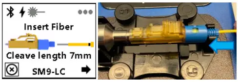 |
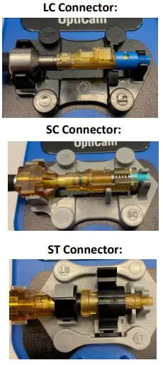
| Step 10 (LC): While keeping forward pressure on the field fiber, cam the connector in the manner appropriate to the connector style. | 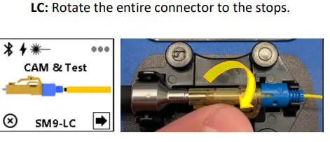 |
| Step 10 (SC): While keeping forward pressure on the field fiber, cam the connector in the manner appropriate to the connector style. | SC: Rotate the cam fin on the top of the connector until it fully stops.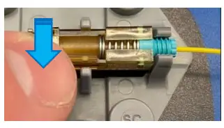 |
| Step 10 (ST): While keeping forward pressure on the field fiber, cam the connector in the manner appropriate to the connector style. |
|
Step 11: Click the selector switch once, quickly (do not hold it down). This will perform the Insertion Loss (IL) calculation. If the connector passes, proceed to Step 12. If the connector fails, un-cam the connector, remove the fiber, and return to Step 4.
|
|
Step 12: Remove the connector from the tool and replace the dust cap. Slide the boot up the fiber and push it onto the rear of the connector. Note that the 900-micron boot is held in place by tension, you do not need to thread it onto the connector. For SC connectors, apply the outer housing. |
|
Note: The full instruction manual for OptiCam® terminations includes additional instructions for 250-micron fiber with build-up tubing, termination onto 1.6/2.0mm and 3.0mm jacketed cable, duplexing connectors, and more. Please refer to FS133: OptiCam® 2 Termination Tool User Manual for further details, available on panduit.com.
Troubleshooting Tips
- Make sure the tool is using the most current version of firmware, as this will often include improvements for the best overall user experience. A USB to Micro USB data cord (e.g. FOCTT2CORD) is required for this process.
- Make sure the tool is set up properly with the right c ord, right cradle, right connector, and right settings to match the intended termination.
- Always replace the batteries with size AA Energizer L91 batteries or similar. Alkaline batteries are not designed for complex electronic devices and will be consumed very rapidly. The tool can also be powered directly via a Micro USB cord to save battery life. The tool will not charge batteries.
- Make sure to properly clean the launch cord every 50 terminations to ensure an optimal function of the tool and user experience. Dirty/damaged launch cords are a leading cause of user difficulty.
- Make sure to do a good, 7mm cleave on the field fiber. Cleave lengths greater than +/- 1mm off will create an increasingly more difficult termination process. Proper use of the cleaver is vital, as a poor cleave is a leading cause of user difficulty.
- Use the help menu on the tool when an error message appears. If further assistance is needed, contact Panduit’s Technical Support team. Most issues are simple to diagnose and remediate.
- The OptiCam 2 tool is not recommended for use outdoors. Sunlight will oversaturate the camera aperture and disrupt the tool’s function. The included magnetic hood (FCCVR2) may help in some situations.
![]()


