
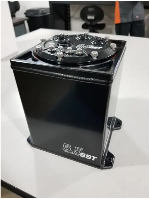
Deatschwerks 6-000-55ST 5.5L Surge Tank
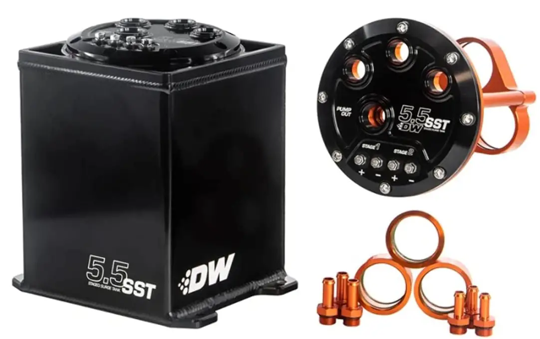
Parts List
- Surge Tank
- Pump Hanger Assembly
- 5/16” Hose Barb to 6AN O-Ring Fittings (x3)
- 3/8” Hose Barb to 6AN O-Ring Fittings (x3)
- 39mm Pump Adapter Sleeves (x3)
- 6AN O-Ring Plug Fittings (x2)
- Ring Terminals (x10)
Suggested Tools
- Wire Stripper and Crimper Tool
- Rubber Hose Cutter
- Screwdriver (Flathead)
- 5mm Allen Wrench
- 8mm Socket or Wrench
- Tape Measure or Ruler
Assembly for Reference
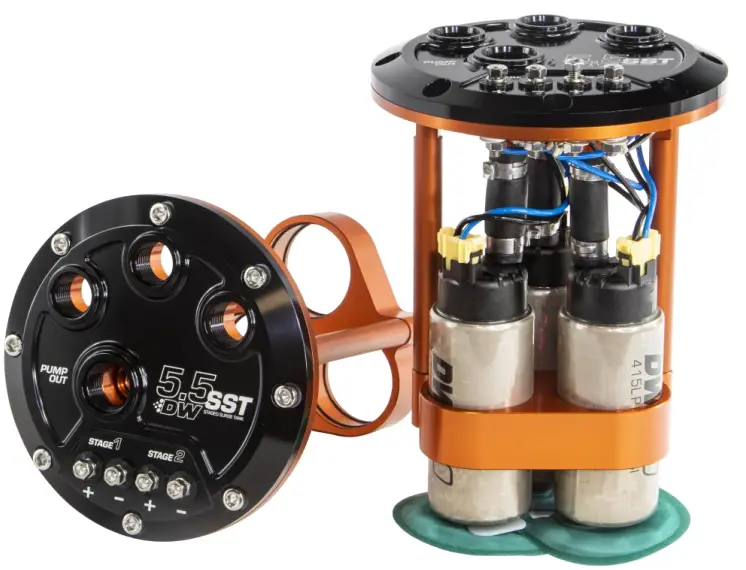
Note The 5.5 Liter Staged Surge Tank is designed to use 39mm or 46mm Deatschwerks Universal fuel pumps and may be incompatible with other brand fuel pumps. Compatible DW Fuel Pumps Included
- DW100 (PN# 9-101-1000)
- DW200 (PN# 9-201-1000)
- DW300 (PN# 9-301-1000)
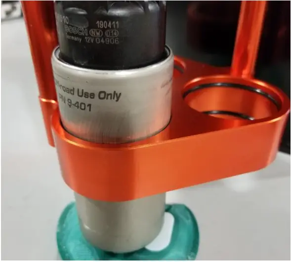
- DW400 (PN# 9-401-1001)
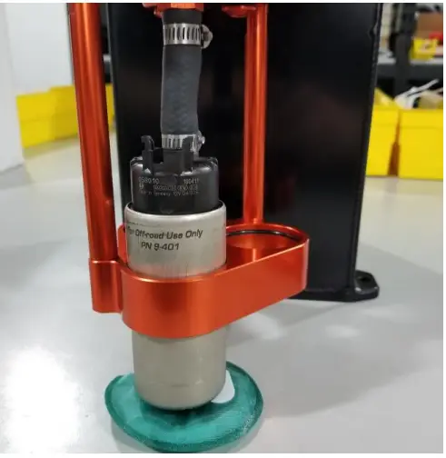
39mm Pump Installation (DW100, 200, or 300)
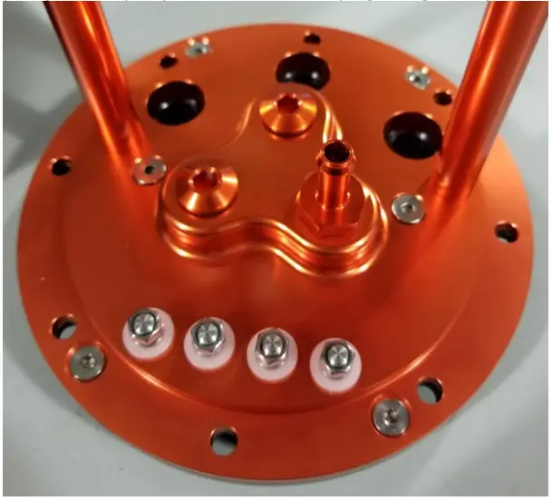
- Install the 5/16” hose barb fitting into the hanger assembly, if only using one or two pumps be sure to place the fitting in the hole that lines up with the main pump outlet, this is the “Primary Stage1” fuel pump location. Place the plug fittings in any unused ports.

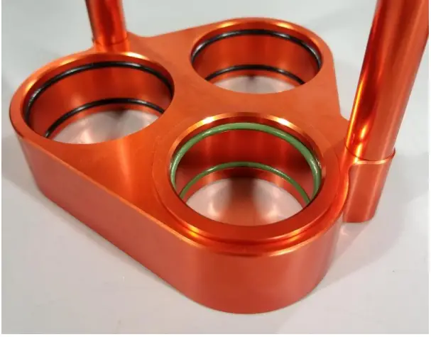
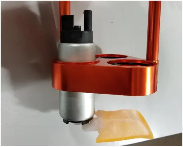
- Insert the 39mm adapter sleeves into the pump holder.

- Install the pump into the pump holder and adapter sleeve, lubrication can ease installation if installation becomes difficult.

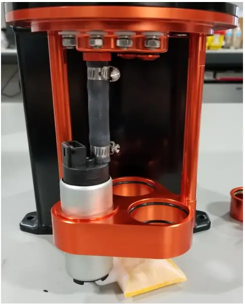
- Install the supplied 3-inches of 5/16” rubber hose and hose clamps between the pump and hose barb fitting.

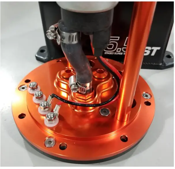
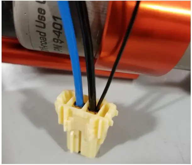
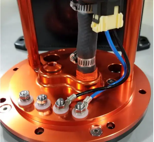
- Cut the included connector harness down to approx. 9-inches long, strip and crimp two of the supplied ring terminals onto the ends. Bolt the ring terminals to the corresponding positive and negative terminals of the stage you are installing, Stage1 (Primary pump) or Stage2 (Secondary pump/s).

- Install the filter sock onto the pump and secure it with the retaining washer. It may be necessary to rotate the pumps once installed to make room for the filter socks.
- Repeat process as needed for additional fuel pumps.
46mm Pump Installation (DW400)
- Install the 3/8” hose barb fittings into the bottom side of the pump hanger assembly to match the 3/8” outlet on the DW400 pump. (Reference Step1 of 39mm Install).
- 46mm pumps do not need the 39mm adapter sleeves, simply install the DW400 pump into the pump holder rings, again lube may be added for an easier install.

- Cut the supplied 3/8” rubber hose to 2.5-inches long and install it with the supplied hose clamps.

- Remove the small black static ground wire from the supplied connector. It is not needed for this application.

- Cut the included connector harness down to approx. 8-inches long, strip and crimp two of the supplied ring terminals onto the ends. Bolt the ring terminals to the corresponding positive and negative terminals of the stage you are installing, Stage1 (Primary pump) or Stage2 (Secondary pump/s).

- Install the filter sock onto the pump. It may be necessary to rotate the pumps once installed to make room for the filter socks.
- Repeat process as needed for additional fuel pumps
- Install the completed pump holder assembly back into the surge tank and tighten the eight M6x1.0 hex bolts in a star pattern. Do not over-tighten 8 ft/lbs max.

Plumbing the Surge Tank
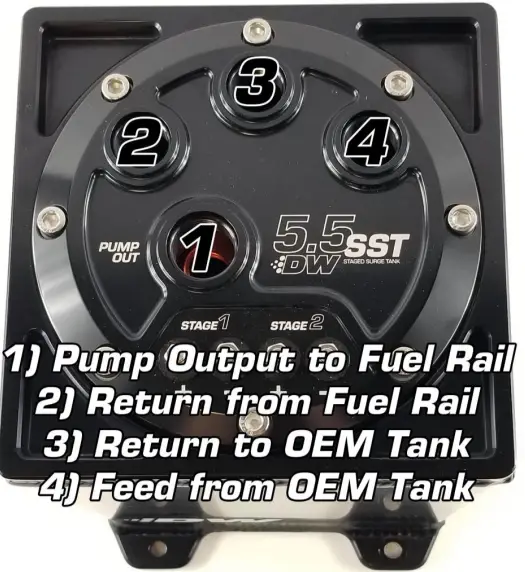
The DW 5.5SST Staged Surge tank has 4 ports on the top, the main pump outlet is labeled and uses a -10AN O-Ring style fitting, this may be adapted down to -8 or -6 with the use of additional fittings (PN# 6-02-0406 or 6-02-0407). The other 3 ports use a -8AN O-Ring style fitting and can be adapted down to -6 if necessary (PN# 6-02-0401). Plumbing of the surge tank is very important, incorrect plumbing can cause a buildup of pressure inside the surge tank and lead to a fuel leaks. All 4 ports on the surge tank must be plumbed none can be blocked off. The ports labeled 2, 3, and 4 can be interchanged if necessary, but port number 1 will always need to go to the feed side of the fuel rail.
- Port #1 will be the high-pressure feed to the fuel rail and injectors.
- Port #2 will be the low-pressure return side of the fuel rail/regulator and will always help keep the surge tank full.
- Port #3 will be a low-pressure return from the surge tank back to the OEM fuel tank, when the surge tank is completely full this hose will allow the excess fuel to flow back
- to the OEM tank.
- Port #4 will be a low-pressure feed from the OEM in-tank feeder fuel pump to the surge tank. (See below for feeder pump suggestions)

Wiring the Surge Tank
The 5.5L Staged Surge tank is designed so you have the ability to turn 1, 2, or 3 pumps on in stages. Running all 3 pumps at the same time is not necessary for light throttle driving or cruising or idling a car, doing so will add excess heat to the fuel system. By running a single pump for 90% of the driving until you need more fuel flow you can lessen the heat and load on the fuel system. Our 5.5SST is designed with 2 stages in mind. Stage 1 for your primary pump to carry the load of idle, cruising and daily driving, and Stage 2 for up to two additional pumps to carry the load of extreme boost or race applications.
NOTE It is possible to run a smaller lower flowing pump as your Stage 1 Primary pump, and a larger higher flowing pump/s as your Stage2.
Wiring
- Stage 1 (Primary) This pump should be wired to activate along with the OEM in-tank feeder pump. It is recommended you use a hardwire kit for this, using the OEM in-tank pump to trigger the Primary Stage 1 pump.
- Stage 2 (Secondary) This stage can be triggered in several different ways depending on your vehicle’s setup. Boosted applications can trigger the second stage with a Hobb-type switch that activates at a low boost pressure typically 0-5psi. This stage can also be triggered with a WOT switch for a Naturally Aspirated setup, or a window switch for a nitrous setup. The best solution if you are running a standalone style ECU would be to set up a second pump output and use that wire to trigger the stage. Using the standalone setup should give access to safety features and other options to trigger like RPM, Load, Injector Duty, etc. It is imperative that Stage 2 be wired with a hardwire kit (PN# FPHWK) due to the current draw of two pumps.
Feeder Pumps
Due to the nature of the surge tank, the in-tank feeder pump sees little to no pressure so even a small OEM fuel pump see’s an increase in flow. Calculating the flow rate of a feed pump for your surge tank can be difficult, due to the increased flow of the feed pump and the returning flow of unused fuel from the rail. We have the following suggestions for feeder pumps with our DW 5.5SST Tank.
- DW100 x 3 inside the 5.5SST, Suggested feeder pump is a single DW100
- DW200 x 3 inside the 5.5SST, Suggested feeder pump is a single DW200
- DW300 x 3 inside the 5.5SST, Suggested feeder pump is a single DW300
- DW300 x1, DW400 x2 inside the 5.5SST, Suggested feeder pump is a DW400
- DW400 x 3 inside the 5.5SST, Suggested Feeder pump is a DW400.
Support
For additional technical support please contact us at: [email protected] or 405.233.3991
FAQs
There are two typical scenarios in which a surge tank is a wise choice for your fuel system…
A surge tank provides a “reserve” supply of fuel to your automobile when it will be subjected to high G-forces at the track in order to prevent fuel starvation. Most cars used for drifting, drag racing, and road racing make excellent candidates for surge tanks.
An extremely adaptable and simple-to-install auxiliary fuel supply can be provided by a surge tank when you need to add more fuel but do not want to replace the OE fuel tank or in-tank pump.
The 2.5L pump holds 2.31L with one pump and 2.13L with two pumps. The 3.5L holds 2.98L with two pumps and 3.25L with one pump. For further details, see our surge tank technology page.
The DW Modular Surge Tanks do not include fittings in order to keep costs down and provide flexibility.
More than 15 psi of pressure cannot be held in the surge tank. As per installation instructions, a vent line from the surge tank to the OE gasoline tank must always be used. The surge tank won’t function properly and could leak if it is compressed.
A great fuel cell substitute is a surge tank. Always double-check your local racing laws.
With each application, a surge tank’s ideal mounting locations change. The frame rail and trunk are two common mounting places. When selecting a location for installation, be sure to give safety plenty of thought. Choose a spot that won’t be subject to high heat, is safe from bodily harm, and is simple to get there.
There is no doubt that installing a tank in the engine compartment is not a good idea. It is not advisable to place fuel reservoirs close to ignition sources. In addition, hotter engine bay temperatures can heat the fuel in the surge tank, which can limit the life of the fuel pump and result in an engine explosion.
In many cases, a surge tank is less expensive and easier to install than a multiple-pump hanger. The surge tank will also get rid of gasoline slosh and low tank pick-up problems.
High power pumps are not required because the surge tank feeder pumps (in-tank) will essentially operate at 0 psi. The OE pump is frequently all that is needed. The quantity and part number of installed in-line pumps will determine the size of the feeder pump that is needed. For a specific power level, the DW Modular Surge Tank Tech documents on the website list the most common configurations.
Surge tanks are used to gauge the flow rate of liquids as well as the total shrinkage and metre factor. The automatic pressure control valve on the gas outlet allows them to maintain a constant back pressure even when being employed as a second-stage separator. Storage is also done with surge tanks.
The most popular method of defense against severe water hammer pressure is surge tanks. These are vertical columns of water, and the air is able to see the water’s surface. They are typically utilized in the penstock upstream of the turbine, however only as close as the conditions permit.
The surge tank functions as a stabilizer by delivering or releasing water during hydraulic transients to minimize damage from the water hammer in the pipeline.
When the cooling system, including the coolant surge tank pressure cap, is warm, never turn the cap. If you ever need to turn the pressure cap, wait until the cooling system and coolant surge tank have cooled. It can be hazardous to fill the cooling system with nothing but water or another liquid.
When the gas springs and pressure rise are known, determine the volume that the gas spring rods will displace when they are retracted using the formulas VDisplaced = Displaced Volume, Vrod = Rod Volume Adder, T = Travel, and N = Number of Gas Springs per Surge Tank. This will allow you to determine the proper surge tank.
A vessel that is positioned in a flowline and through which liquids or gases are pumped to counteract pressure fluctuations.


