 DMX512 Ultra-Pro 5CH RDM Decoder
Instruction Manual
Important: Read All Instructions Prior to Installation
Function introduction
Product Data
| Input Voltage | Output Current | Output Power | Remarks | Size(LxWxH) | Protection |
| 12-24VDC | 5x8A | 5x(96-192)W | Constant voltage | 164x73x38mm | Short circuit |
| 12-4BVDC | 5x350mA | 5x(4.2-16.B)W | Constant current | 164x73x38mm | Short circuit |
| 12-48VDC | 5x700mA | 5x(8.4-33.6)W | Constant current | 164x73x38mm | Short circuit |
- Master & decoder mode, RDM function
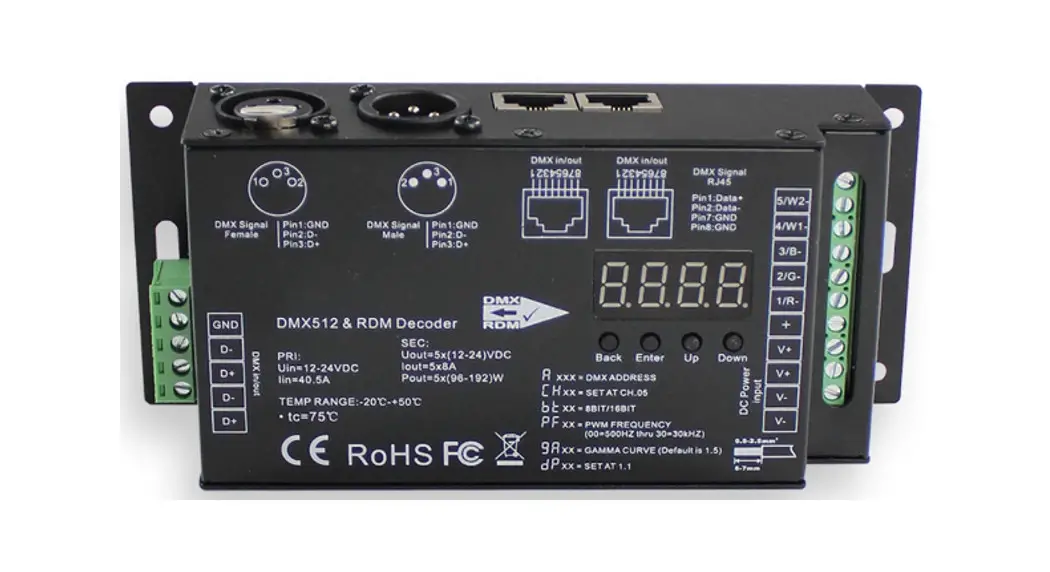
- Metal housing, digital display to show data directly, easy to set and show DMX address.
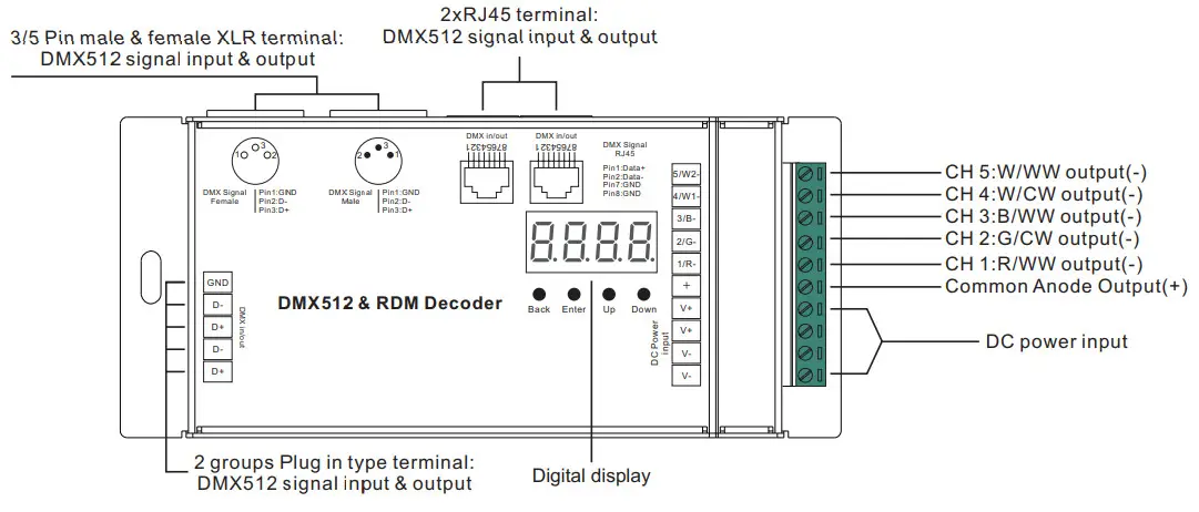
- With multiple kinds of DMX in/out ports: RJ 45, XLR, and normal screws.
- Total 5 PWM output channels, common anode. DMX channel quantity from 1CH~5CH settable
- PWM output resolution ratio 8bit, 16bit settable.
- Output PWM frequency from 500HZ ~ 35K HZ settable.
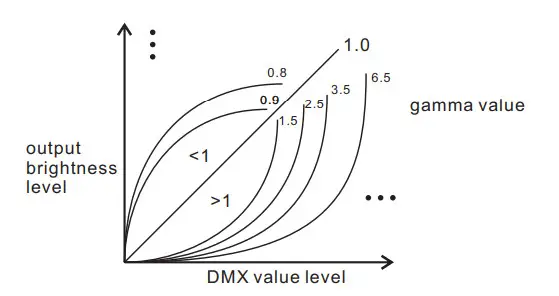
- Output dimming curve gamma value from 0.1 ~ 9.9 settable.
- The decoding mode is settable.
- Galvanic isolation
Safety & Warnings
- DO NOT install with power applied to the device.
- DO NOT expose the device to moisture.
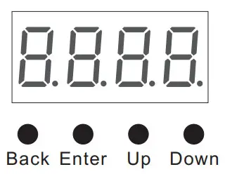
Operation
Before you do other settings, please set the device to Master or Decoder mode.![]() = DMX Decoder mode ,
= DMX Decoder mode , ![]() = DMX Master mode(stand alone).
= DMX Master mode(stand alone).
Keep on clicking the Down button, to get run1 or run2, then click Enter, then click the Down button to choose 1 or 2, then click the Back button.
I. For run2 DMX Master mode: Keep on clicking the Up button, and you will find the following menus on display:
![]() This means brightness for each output PWM channel. First 1 means PWM output channel 1 and it is selectable from 1 to 5 by clicking the “UP” or “Down” button. Second 01 means brightness level, click the “Enter” button, and the display flashes, then click the “UP” or “Down” button to select from 00-99-FL, which means 0%-99%-100% brightness, then click the “Back” button to confirm.
This means brightness for each output PWM channel. First 1 means PWM output channel 1 and it is selectable from 1 to 5 by clicking the “UP” or “Down” button. Second 01 means brightness level, click the “Enter” button, and the display flashes, then click the “UP” or “Down” button to select from 00-99-FL, which means 0%-99%-100% brightness, then click the “Back” button to confirm.
![]() XXX Means programs, a total of 1~31 programs.
XXX Means programs, a total of 1~31 programs.![]() XX Means RGB running effect’s brightness, total of 1~8 levels of brightness
XX Means RGB running effect’s brightness, total of 1~8 levels of brightness![]() X Means effect play speed. total 1~9 levels speed.
X Means effect play speed. total 1~9 levels speed.
P-XX means RGB color-changing modes, total of 31 programs:
00- RGB off
01- Static red
02- Static green
03- Static Blue
04- Static yellow (50% red+50% green)
05- Static orange (75% red+25% green)
06- Static cyan (50% green+50% blue)
07- Static purple (50% blue+50% red)
08- Static white (100% red+100% green+100% blue)
09- Any two colors of RGB mix fade, changing diagram as follow: 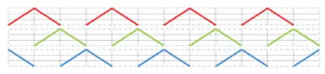 11- RGB FADE OUT & FADE IN, changing diagram as follow:
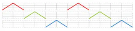 13- RGB FADE IN, changing diagram as follow:
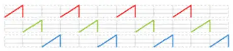 10- RGB colors mix fade, changing diagram as follow:
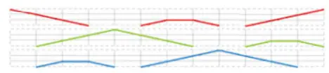 12- RGB jump changing, changing diagram as follow:
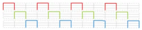
14- RGB FADE OUT, changing diagram as follow: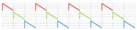 15- RGB 3 colors strobe
16- White color strobe (100% red+100% green+100% blue)
17- 7 colors FADE OUT & FADE IN (red, orange, yellow, green, cyan, blue, purple FADE OUT & FADE IN)
18- 7 colors jump changing (red, orange, yellow, green, cyan, blue, purple jump changing)
19- 7 colors strobe (red, orange, yellow, green, cyan, blue, purple strobe)
20- Red-white (100% red+100% green+100% blue) circle gradual changing
21- Green-white (100% red+100% green+100% blue) circle gradual changing
22- Blue-white (100% red+100% green+100% blue) circle gradual changing
23- Red-orange circle gradual changing
24- Red-purple circle gradual changing
25- Green-yellow circle gradual changing
26- Green-cyan circle gradual changing
27- Blue-purple circle gradual changing
28- Blue-cyan circle gradual changing
29- Red-yellow-green circle gradual changing
30- Red-purple-blue circle gradual changing
31- Green-cyan-blue circle gradual changing
II. For run1 DMX decoder mode: Keep on clicking the Up button, and you will find the following menus on display:
DMX signal indicator:: • When DMX signal input is detected, the indicator on the display following ![]() turns red
turns red![]() XXX
XXX
![]() XXX Means DMX address. fa ctory defaults setting is 001.
XXX Means DMX address. fa ctory defaults setting is 001.![]() XX Means DMX channels quantity. factory defaults setting is Ch05
XX Means DMX channels quantity. factory defaults setting is Ch05![]() XX Means Bit (8bit or 16bit). factory defaults setting is 16bit
XX Means Bit (8bit or 16bit). factory defaults setting is 16bit![]() XX Means output PWM frequency. factory defaults setting is 1K HZ
XX Means output PWM frequency. factory defaults setting is 1K HZ![]() XX Means output dimming curve gamma value, factory defaults setting is ga 1.5
XX Means output dimming curve gamma value, factory defaults setting is ga 1.5![]() XX Means Decoding mode, factory defaults setting is dp1.1
XX Means Decoding mode, factory defaults setting is dp1.1
By holding the button Back + Enter together at the same time for over 5 seconds until the display goes off, it will restore to default settings.
Wiring diagram
- Work as Master mode

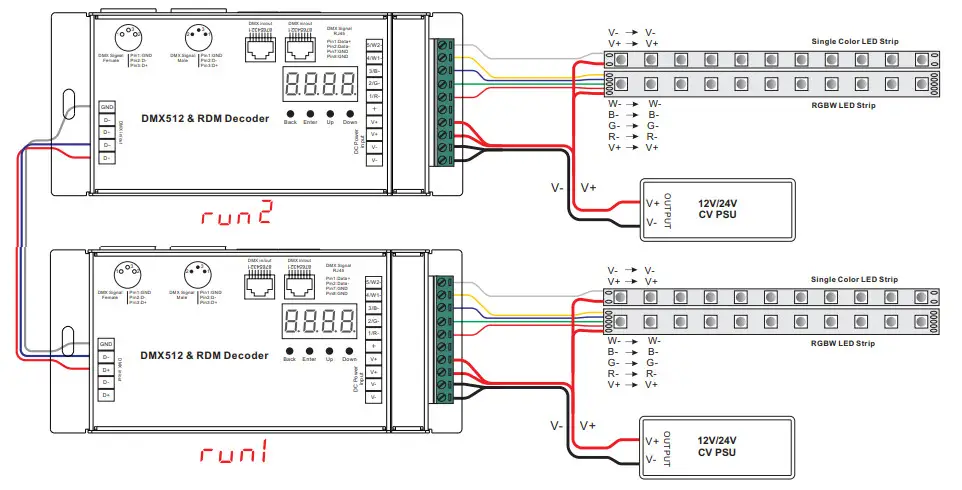
Work as Decoder mode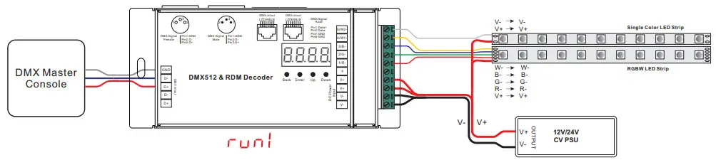
Note: the terminal blocks used for the input have two spaces for Voltage + and two spaces for GND which allow for the huge current capability this unit has 5 X 8A = 40 AMPS of power!
2) Please make sure that the stripped wires are fully inserted into the terminal blocks and screws are tightened!
1. DMX address setting:
select menu ![]() XXX, click the button “Enter”, display flashes, then click or hold the button “Up” / “Down” to set the DMX address (click is slow, the hold is fast.), then click the button“Back” to confirm.
XXX, click the button “Enter”, display flashes, then click or hold the button “Up” / “Down” to set the DMX address (click is slow, the hold is fast.), then click the button“Back” to confirm.
2. DMX channel quantity setting:
Select menu ![]() XX, click the button “Enter”, display flashes, then click the button “Up” / “Down” to set DMX channel quantity, then click the button“Back” to confirm.
XX, click the button “Enter”, display flashes, then click the button “Up” / “Down” to set DMX channel quantity, then click the button“Back” to confirm.
For example, the DMX address is already set to 001.
CH01=1 DMX address for all the output channels, which are all address 001.
CH02=2 DMX addresses, output 1&3 is address 001, output 2,4&5 is address 002
CH03=3 DMX addresses, output 1, 2 is address 001,002, output 3,4&5 is address 003
CH04=4 DMX addresses, output 1,2,3 is address 001,002,003, output 4&5 is address 004
CH05=5 DMX addresses, output 1,2,3,4,5 is address 001,002,003,004,005.
3. PWM output resolution Bit setting:
select menu![]() XX, click the button “Enter”, display flashes, then click the button “Up” / “Down” to choose 08 or 16 bit, then click the button“Back” to confirm.
XX, click the button “Enter”, display flashes, then click the button “Up” / “Down” to choose 08 or 16 bit, then click the button“Back” to confirm.
4. output PWM frequency setting:
select menu ![]() XX, click the button “Enter”, display flashes, then click the button “Up” / “Down” to choose 00~35, then click the button“Back” to confirm. 00=500HZ, 01=1kHZ, 02=2kHZ…..25=25kHZ, 35=35kHZ.
XX, click the button “Enter”, display flashes, then click the button “Up” / “Down” to choose 00~35, then click the button“Back” to confirm. 00=500HZ, 01=1kHZ, 02=2kHZ…..25=25kHZ, 35=35kHZ.
5. output dimming curve gamma value setting:
select menu![]() XX, click the button “Enter”, display flashes, then click or hold the button “Up” / “Down” to choose 0.1~9.9, then click the button“Back” to confirm.
XX, click the button “Enter”, display flashes, then click or hold the button “Up” / “Down” to choose 0.1~9.9, then click the button“Back” to confirm.
6. DMX decoding mode setting:
Select menu ![]() XX, click the button “Enter”, display flashes, then click or hold the button “Up” / “Down” to choose the decoding mode, then click the button“Back” to confirm. “dPxx” means the DMX address quantity used for control of corresponding PWM output channel quantity. 1st “x” is DMX address quantity, 2nd “x” is PWM channel quantity.
XX, click the button “Enter”, display flashes, then click or hold the button “Up” / “Down” to choose the decoding mode, then click the button“Back” to confirm. “dPxx” means the DMX address quantity used for control of corresponding PWM output channel quantity. 1st “x” is DMX address quantity, 2nd “x” is PWM channel quantity.
Fine dimming: the fine dimming effect can only be visible when the dimming curve gamma value is set lower than 1.4, and the lower the value is, the more visible the fine dimming effect will be.
DMX address is 001, CH01
| DMX Console Slider number | dp1.1 | dp2.1 |
| DMX channel | ||
| 1 | for all output dimming | for all output dimming |
| 2 | No use | for all output fine dimming |
DMX address is 001, CH02
| DMX Console Slider number | dp1.1 | dp2.1 | dp3.2 |
| DMX channel | |||
| 1 | for output 1&3 dimming | for output 1&3 dimming | for output 1 &3 dimming |
| 2 | for output 2,4 &5 dimming | for output 1&3 fine dimming | for output 2,4 &5 dimming |
| 3 | for output 2,4 &5 dimming | for all output dimming | |
| 4 | for output 2,4&5 fine dimming |
DMX address is 001, CH03
| DMX Console Slider number | dp1.1 | dp2.1 | dp4.3 | dp5.3 |
| DMX channel | ||||
| 1 | for output 1 dimming | for output 1 dimming | for output 1 dimming | for output 1 dimming |
| 2 | for output 2 dimming | for output 1 fine dimming | for output 2 dimming | for output 2 dimming |
| 3 | for output 3,4 &5 dimming | for output 2 dimming | for output 3,4&5 dimming | for output 3,4&5 dimming |
| 4 | for output 2 fine dimming | for all output master dimming | for all output master dimming | |
| 5 | for output 3,4 &5 dimming | strobe effects | ||
| 6 | for output 3,4&5 fine dimming |
DMX address is 001, CH04
| DMX Console Slider number DMX channel | dp1.1 | dp2.1 | dp5.4 | dp6.4 |
| 1 | for output 1 dimming | for output 1 dimming | for output 1 dimming | for output 1 dimming |
| 2 | for output 2 dimming | for output 1 fine dimming | for output 2 dimming | for output 2 dimming |
| 3 | for output 3 dimming | for output 2 dimming | for output 3 dimming | for output 3 dimming |
| 4 | for output 4&5 dimming | for output 2 fine dimming | for output 4&5 dimming | for output 4&5 dimming |
| 5 | for output 3 dimming | for all output master dimming | for all output master dimming | |
| 6 | for output 3 fine dimming | strobe effects | ||
| 7 | for output 4 &5 dimming | |||
| 8 | for output 4&5 fine dimming |
DMX address is 001, CH05
| DMX Console Slider number DMX channel | dp1.1 | dp2.1 | dp6.5 | dp7.5 |
| 1 | for output 1 dimming | for output 1 dimming | for output 1 dimming | for output 1 dimming |
| 2 | for output 2 dimming | for output 1 fine dimming | for output 2 dimming | for output 2 dimming |
| 3 | for output 3 dimming | for output 2 dimming | for output 3 dimming | for output 3 dimming |
| 4 | for output 4 dimming | for output 2 fine dimming | for output 4 dimming | for output 4 dimming |
| 5 | for output 5 dimming | for output 3 dimming | for output 5 dimming | for output 5 dimming |
| 6 | for output 3 fine dimming | for all output master dimming | for all output master dimming | |
| 7 | for output 4 dimming | strobe effects | ||
| 8 | for output 4 fine dimming | |||
| 9 | for output 5 dimming | |||
| 10 | for output 5 fine dimming |
The data definitions for the strobe channel are as follows:
{0, 7},//undefined
{8, 65},//slow strobe–>fast strobe
{66, 71},//undefined
{72, 127},//slow push fast close
{128, 133},//undefined
{134, 189},//slow close fast push
{190, 195},//undefined
{196, 250},//random strobe
{251, 255},//undefined
The supported RDM PIDs are as follows:
DISC_UNIQUE_BRANCH
DISC_MUTE
DISC_UN_MUTE
DEVICE_INFO
DMX_START_ADDRESS
IDENTIFY_DEVICE
SOFTWARE_VERSION_LABEL
DMX_PERSONALITY
DMX_PERSONALITY_DESCRIPTION
SLOT_INFO
SLOT_DESCRIPTION
MANUFACTURER_LABEL
SUPPORTED_PARAMETERS
MODULATION_FREQUENCY
MODULATION_FREQUENCY_DESCRIPTION CURVE
CURVE_DESCRIPTION
RDM Discovery Indication:
When using RDM to discover the device, the digital display will flash and the connected lights will also flash at the same frequency to indicate. Once the display stops flashing, the connected light also stops flashing.
Restore to Factory Default Setting
Press and hold down both “ ” and “Enter” keys Back
until the digital display turns off, then release the keys, the system will reset and the digital display will turn on again, all settings will be restored to factory default.
Default settings are as follows:
DMX Address Code: a001
DMX Address Quantity: SW1=0: ch05, SW1=1: ch04
PWM Resolution Mode: bt16
PWM Frequency: pf01
Gamma: ga1.5
Decoding Mode: dp1.1
Product Dimension
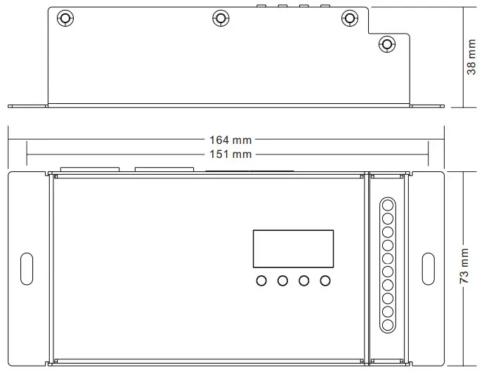
![]()


