

LANZAR VIBEX6 3-Way Electronic Audio Crossover
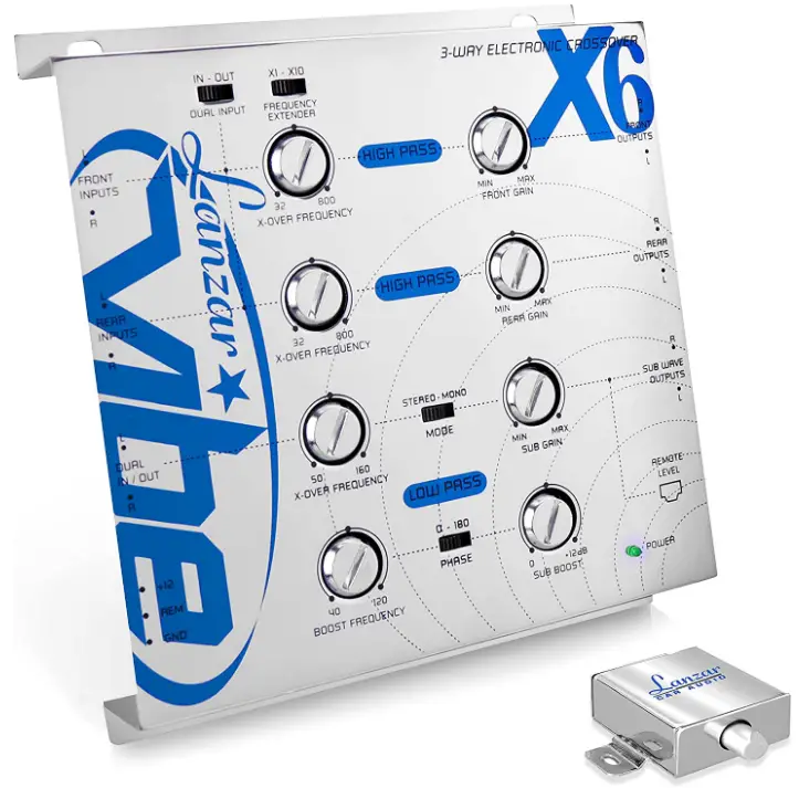
FEATURES
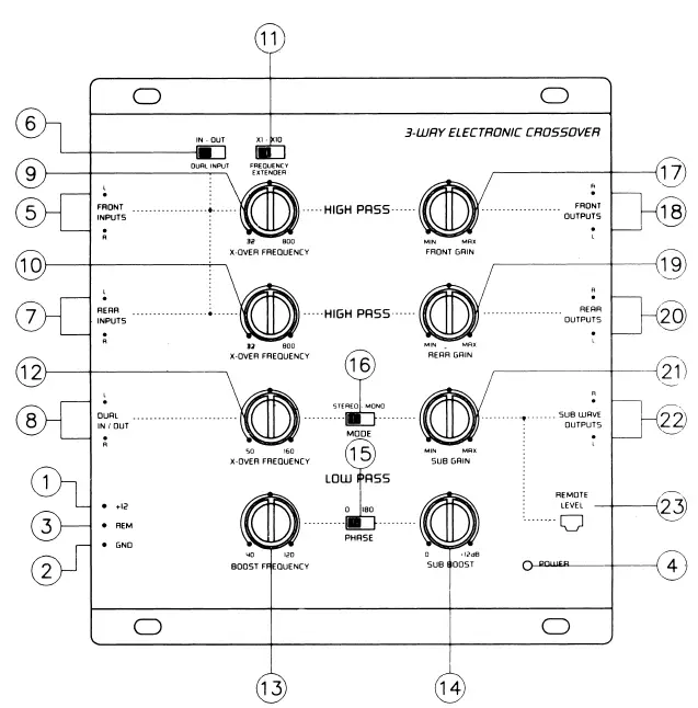
FUNCTIONS
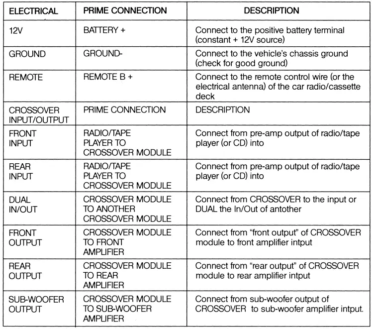
- POWER INPUT TERMINAL (12V)
To be connected to the positive terminal of your vehicle battery or other constant+ 12V source. - GROUND INPUT TERMINAL
To be wired to the vehicle’s chassis ground. - REMOTE TURN-ON INPUT TERMINAL (REMOTE)
To be connected to the remote control wire or antenna lead of the source unit for remote ON/OFF. - POWER INDICATOR
This indicator lights up when the internal switching power supply is activated and the unit is operational. - LEFT /RIGHT FRONT CHANNEL SIGNAL INPUTS
To be connected to the front channel output of the source unit. - DUAL INPUT SWITCH
“IN”: When the parallel input is at the “IN” position, the input signals coming in through the front channel signal inputs are split and directed to the front and rear channels simultaneously. (T his feature is to be engaged where the source unit has no separate front, rear or subwoofer channel outputs.)
“OUT”: If the source unit has independent front and rear channel outputs, disengage the parallel input by sliding the switch to the “OUT” positiion. - LEFT/RIGHT REAR CHANNEL SIGNAL INPUTS
To be connected to the rear channel outputs of the source unit. BUT MAKE SURE THAT THE DUAL INPUT SWITCH IS AT THE “OUT” POSITION. - LEFT /RIGHT DUAL IN/OUT TERMINALS
As Input Terminal: To be connected to the subwoofer output of the source unit.
As output Terminal: To be connected to the front channel input terminal of another electronic crossover in a multi-crossover system. - FRONT CHANNEL HIGH-PASS FREQUENCY SELECTOR
For selection of front channel high-pass crossover frequency between 32 Hz and 800 Hz (or 320 Hz and SK Hz when its frequency multiplier is at “x10” position). - REAR CHANNEL HIGH-PASS FREQUENCY SELECTOR
For selection of rear channel high-pass crossover frequency between 32 Hz and 800 Hz. - FRONT CHANNEL HIGH-PASS FREQUENCY EXTENDER
Positioning this switch at the “x10” position changes, the range of selectable crossover frequency for the front channel high-pass from 32 Hz – 800 Hz to 320 Hz – 8K Hz. - SUBWOOFER FREQUENCY SELECTOR
For selection of the low-pass crossover frequency for the subwoofer channel between 50 Hz and 160 Hz. - BASS-BOOST FREQUENCY CONTROL
For setting the frequency (from 40 Hz to 120 Hz) at which the BASS-BOOSf circuitry generates frequency boost to equalize the woofer enclosure. - BASS-BOOST LEVEL CONTROL
For selection of the boost level (from Oto +12 dB). - PHASE INVERTER
Positioning the switch to the “180” positiion shifts the subwoofer output signals 180 degrees out-of-phase relative to the front and rear output signals. - SUBWOOFER STEREO/MONO SWITCH
For selection of stereo or mono mode subwoofer output. - FRONT CHANNEL OUTPUT GAIN CONTROL
For adjusting the front channel output signal level. - LEFT/RIGHT FRONT CHANNEL OUTPUT TERMINALS
To be connected to the front channel amplifier left/right inputs. - REAR CHANNEL OUTPUT GAIN CONTROL
For adjusting the rear channel output signal level. - LEFT/RIGHT REAR CHANNEL OUTPUT TERMINALS
To be connected to the rear channel amplifier left/right inputs. - SUBWOOFER OUTPUT GAIN CONTROL
For adjusting the subwoofer channel output signal level. - LEFT/RIGHT SUBWOOFER OUTPUT TERMINALS
To be connected to the subwoofer channel amplifier left/right inputs. - SUBWOOFER OUTPUT LEVEL REMOTE CONTROL TERMINAL
To be connected to the remote control for exclusive maneuver of the subwoofer output level, and the subwoofer output level control on the unit (“21 ” above) is by-passed.
ELECTRICAL & AUDIO CONNECTIONS
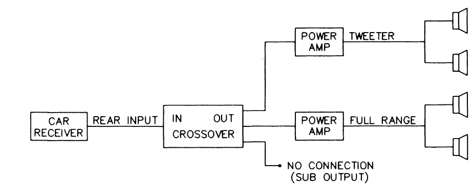
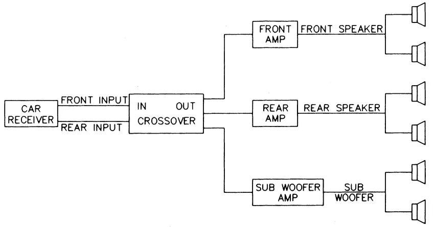
(A) 2-Channel Two-Way System
(tweeter + full range)
(B) 2-Channel Two-Way System
(tweeter + woofer)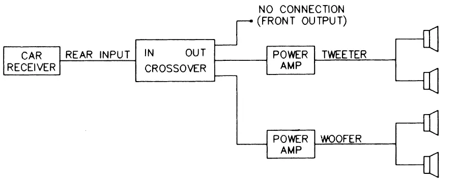
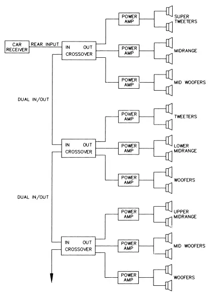
(C) 4-Channel TRI-AMP System
(D) 2-Channel multiple purpose system
ELECTRICAL & AUDIO CONNECTIONS
Precautions
- To prevent short circuits, be sure to disconnect the negative battery ground lead before wiring the system up.
- When you finish the installation, be sure to make one more check to be sure everything is done correctly.
- Reinstate all car parts theat were removed.
- Reconnect the negative battery ground lead.
Primary Wiring Descriptions
NOISE CHECK & SYSTEM ADJUSTMENT
NOISE CHECK
Check the entire audio system for noise before permanently securing the CROSSOVER mounting
- Start the engine.
- Turn the audio system on.
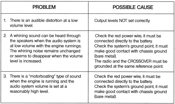
- Rev the engine and vary the VOLUME of the audio system to determine if there is any unwanted noise. If so, turn both the audio system and the engine off. Do not secure the CROSSOVER mopunting screws. Refer to the “Trouble Shooting Guide” at this manual.
- If the audio system does not have any noise, securely tighten the CROSSOVER mounting screws and double check the wiring cables for safe placement.
SYSTEM ADJUSTMENT
Prelimnary Adjustments
Pre-setting the system provides a necessary starting point for fine-tuning the entire audio system to maximum performance.
NOTE: DO NOT MOUNT CROSSOVER UNTIL THE FOLLOWING PROCEDURES HAVE BEEN COMPLETED.
- Preset each amplifier input gain adjustment at the amplifier to half of maximum.
- Before turning the audio system on, preset-adjust the front, rear and sub-woofer output level controls, as well as the front channel high-pass and sub-woofer channel low-pass crossover points.
- Slowly turn the volume up and listen carefully for: Obvious trouble in sound (distortion, no sound, no hiss, total silence). Turn the system off refer to “Trouble Shooting Guide” at this manual.
Caution
DO NOT ROUTE AUDIO CABLES AND POWER CABLES TOGETHER! THIS CAN CAUSE ENGINE NOISE IN YOUR AUDIO SYSTEM. ALWAYS DISCONNECT THE SYSTEM FROM THE BATTERY BEFORE ATTEMPTING TO MAKE OR ALTER ANY CONNECTIONS. THIS PRODUCT IS DESIRED FOR USE IN ANY 12 VOLTS NEGATIVE GROUND ELECTRICAL SYSTEM ONLY. INSTALLING THIS PRODUCT IN ANY POSITIVE GROUND ELECTRICAL SYSTEM COULD SERIOUSLY DAMAGE THE AUDIO SYSTEM.
TROUBLESHOOTING GUIDE
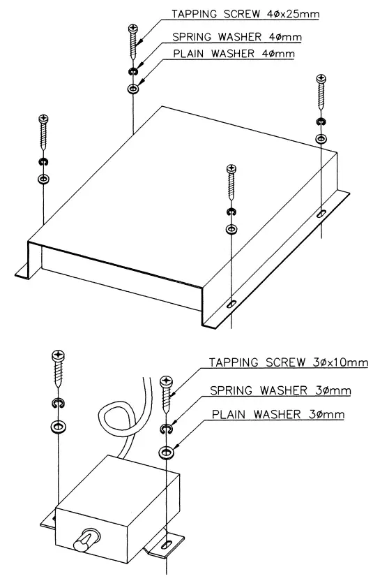
INSTALLATION
SPECIFICATIONS
- POWER SOURCE:4 volts DC negative ground
- INPUT CURRENT:5 amp max
- DISTORTION:01 % THO at 1 V output level
- FREQUENCY RESPONSE: 10Hz-30KHz ± 3dB
- SIN ratio (A weighted): > 95 dB
- SEPARATION: 60 dB
Crossover frequencies (continuously variable):
- Front High-pass: (x1): 32 – 800 Hz; (x10): 320- SK Hz
- Rear High-pass: 32 – 800 Hz
- Subwoofer: 50 -160 Hz
- Crossover slope rate: 12 dB per octave 2nd Order Butterworth
- Subwoofer boost: Single octave 0 dB to 12 dB (variable) at 40t o 12 0 Hz(variable)
- Input impedance: > 10KOhms
- Output impedance: < 1 K Ohms
- Output gain: + 3dB
- Output voltage level: 5 volts max.
- Dimensions: 6-7/S”W x 7- 1 /2 “Lx 1- 3/8″H( 1 75mm x 191mm x 35mm)
FEATURES AND SPECIFICATIONS SUBJECT TO C HANGE AND / OR IMPROVEMENT WITHOUT
FAQs
In order to create a 3-way crossover, low-pass, band-pass, and high-pass filters are combined (LPF, BPF and HPF respectively). The HPF and LPF sections are combined to form the BPF part.
By acting as a filter, a crossover keeps undesirable frequencies from reaching a speaker or group of speakers. This is really helpful since it enables us to send each speaker a specified frequency range that will allow for the most effective and efficient playback.
It is split between the midrange/high frequency drivers and the low-frequency driver (subwoofer) for a three-way speaker (tweeter). A proper crossover is essential because it must deliver an even signal to the speakers without introducing distortion.
Yes. Sound quality is mostly dependent on crossover design. Low quality sound will be produced by even the greatest speaker drivers with subpar crossover designs and voicing. The greatest sound will always be produced by a system that combines high-quality speaker drivers, expertly designed crossovers, and optimum cabinet geometry and design.
First, they can employ a crossover network or just a number of capacitors. When maintained, capacitors have a maximum lifespan of about 30 years before they begin to deteriorate. This degradation could happen more quickly due to heavy use or defective parts, which would lower the speaker’s ability to deliver high-quality sound.
Crossovers typically provide a smoother, more comfortable ride, handle better, are simpler to manoeuvre and park, and have a tendency to stop faster than standard SUVs because they are constructed on unibody frames like road vehicles.
They are referred to as “active” since they require power to operate. Unlike active crossovers, passive (speaker) crossovers don’t need a power source to operate. Instead, they are positioned between the amplifier and the speakers, filtering out undesirable frequencies. Built-in speakers are a common form of passive crossovers.
It raises the overall volume for all input frequencies. To make REL volume equal to the speaker, the Level control should be modified (s). A tuneable electrical circuit called the crossover in a REL filters out frequencies above the range of the sub bass system’s operation.
Using a speaker crossover in an audio system has a number of benefits. Clarity is the primary and most obvious factor. More accurate sounds will result by separating the bass from the treble and sending those frequencies to three different speaker drivers with expertise in those frequencies.
The crossover frequencies for three drivers, not two, are used in three-way crossovers. You would have to choose between giving up treble, bass, or midrange in order to use it as a two-way system; you couldn’t have all three. Options
A crossover is required for sound to be sent to the proper driver in any audio system, including the one in your car. High, midrange, and low frequencies should be delivered to tweeters, woofers, and subs, accordingly. The interior of every full-range speaker is a crossover network.
As long as the sine wave is within the frequency range that the crossover itself lets through, an ideal crossover has no losses and has no impact on the power delivered to the speaker. Real crossovers experience a little degree of power loss as a result of the inductor’s resistance.
Your speakers can handle cleanly if you set the crossover point approximately 10 Hz above the lowest frequency and are aware of the frequency range of your speakers. The THX standard and the most popular crossover frequency is 80 Hz.
The frequency at which sound switches from one speaker to another is known as the crossover frequency. Where the sound transitions from the speaker channels to a subwoofer is determined by the electrical crossover components in a passive speaker.
Film capacitors with low dielectric absorption and corresponding series resistance are frequently employed for a crossover network’s best performance. The best option for audio applications is film capacitors because of its properties.
A type of distortion called crossover distortion results from switching between motors driving a load. Although it occasionally occurs in other kinds of circuits as well, it is most frequently encountered in complementary, or “push-pull,” Class-B amplifier stages.


