
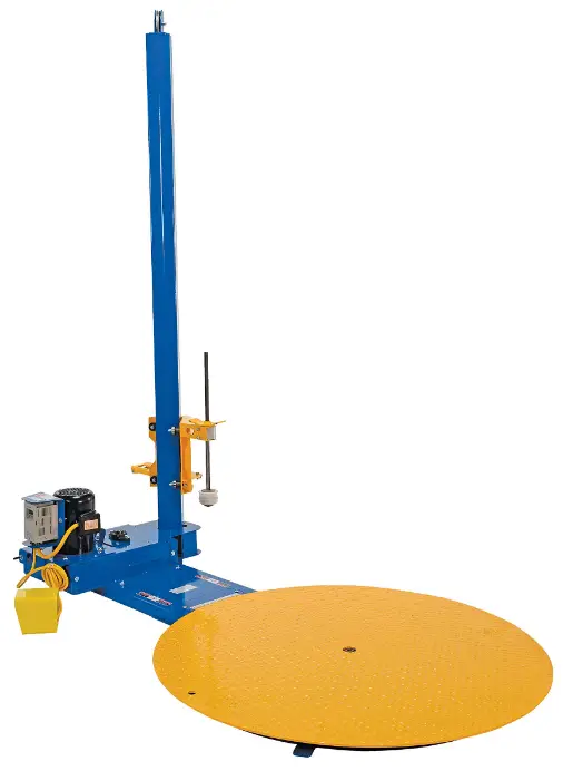
Vestil SWA-50 50 Inch Semi-Automatic Stretch Wrap Machine
Receiving Instructions
After delivery, remove the packaging from the product. Inspect the product closely to determine whether it sustained damage during transport. If damage is discovered, record a complete description of it on the bill of lading. If the product is undamaged, discard the packaging.
NOTE: The end-user is solely responsible for confirming that product design, use, and maintenance comply with laws, regulations, codes, and mandatory standards applied where the product is used.
Technical Service & Replacement Parts
For answers to questions not addressed in these instructions and to order replacement parts, labels, and accessories, call our Technical Service and Parts Department at (260) 665-7586. The department can also be contacted online at https://www.vestil.com/page-parts-request.php.
Electronic copies of Instruction Manuals
Additional copies of this instruction manual may be downloaded from https://www.vestil.com/page-manuals.php.
SPECIFICATIONS
Thank you for purchasing a semi-automatic stretch wrap machine made by Vestil Manufacturing Company (“Vestil”). Our wrapping machines are designed for dependability and incorporate numerous safety-enhancing features. Although use and maintenance procedures are relatively intuitive, all persons who might use or maintain this product must familiarize themselves with the instructions provided in this manual.
Notable features of standard models include
- Carousel rotation controlled by a (foot) pedal switch connected to an 8 foot cord. The standard 115V, variable AC motor allows adjustable rotation speeds of 3-12 rpm and includes soft-starting and stopping capability.
- Adjustable stretch-wrap tension controlled by a friction-brake assembly. Film placement is controlled manually by moving the carriage assembly up and down on the vertical mast. An easy-to-release, hand operated carriage-brake allows the carriage to move freely making film application fast and simple.
- Adaptability to use stretch wrap rolls 10″-20″ long.
- Minimal assembly is necessary. Each wrapping machine is shipped with the mast disconnected. Assembly simply requires raising the mast and bolting it in place.
- The stretch-wrap delivery mechanism can be upgraded to a 115V, single phase, AC-powered mast option (PMO).
- Ability to be used in conjunction with an optional ramp, which allows the operator to load and unload the machine with a pallet truck.
Dimensions and other product specifications of standard wrapping machine models appear in the following tables
| Model | Turntable diameter | Maximum service height | Turntable height | Uniform capacity | Net weight | ||||
| SWA-50 | 50in. (127cm) | 82in. (208.3cm) | 2in. (5cm) | 4,000lb. (1,818kg) | 499lb. (~226.8kg) | ||||
| SWA-70 | 70in. (178cm) | 82in. (208.3cm) | 21/4in. (5.7cm) | 4,000lb. (1,818kg) | 926lb. (~420.9kg) | ||||
| SWA-51-LP | 51in. (129.5cm) | 83in. (211cm) | 1in. (2.5cm) | 4,000lb. (1,818kg) | 470lb. (~214kg) | ||||
| Optional equipment | |||||||||
| Model | Description | Weight in pounds (~kg) | |||||||
| SWA-5070LP-PMO | Powered mast option (50in. and 70in. diameter) | 400lb. (~181.8kg) | |||||||
| SWA-50-R-4848 | Approach ramp: 48in. x 48in. x 2in. (W x L x H) | 150lb. (~68.2kg) | |||||||
| SWA-70-R-4848 | Approach ramp: 48in. x 48in. x 2in. (W x L x H) | 268lb. (~121.8kg) | |||||||
| SWA-50-SCALE | Digital scale (50in. diameter) | 680lb. (~309.1kg) | |||||||
| SWA-70-SCALE | Digital scale option (70in. diameter) | 884lb. (~401.8kg) | |||||||
| SWA-50-R-4860-SCL | Approach ramp for scale option | 346lb. (~157.3kg) | |||||||
| SWA-70-R-4860-SCL | Approach ramp for scale option | 335lb. (~152.3kg) | |||||||
SIGNAL WORDS
- SIGNAL WORDS appear in this manual to draw the reader’s attention to important safety-related messages. The following are signal words used in this manual and their definitions.
- DANGER: Identifies a hazardous situation which, if not avoided, WILL result in DEATH or SERIOUS INJURY. Use of this signal word is limited to the most extreme situations.
- WARNING: Identifies a hazardous situation which, if not avoided, COULD result in DEATH or SERIOUS INJURY.
- CAUTION: Indicates a hazardous situation which, if not avoided, COULD result in MINOR or MODERATE injury.
- NOTICE: Identifies practices likely to result in product/property damage, such as operation that might damage the product.
SAFETY INSTRUCTIONS
Vestil strives to identify foreseeable hazards associated with the use of its products, but no manual can address every conceivable risk. Minimize the likelihood of injury by observing the hazards identified below and by inspecting and maintaining the product as instructed in INSPECTIONS & MAINTENANCE.
WARNING
Risks of serious personal injuries or death.
- Read and understand the entire manual before assembling, using or servicing the device. Read the manual to refresh your understanding of proper use and maintenance procedures whenever necessary.
- DO NOT modify the product in any way UNLESS you first obtain written approval from Vestil. Unauthorized modifications automatically void the Limited Warranty and might make the product unsafe to use.
- Read the manual to refresh your understanding of proper use and maintenance procedures.
- DO NOT exceed the maximum rated load. See Label 1153 in LABELING DIAGRAM on p. 17.
- DO NOT stand or sit on the turntable or on the load at any time.
- Loads must not extend over the edge of the turntable.
- DO NOT pick up the unit (with a forklift, for example) unless the entire frame is supported. The frame might bend if it is inadequately supported.
- Install the machine ONLY on even, level surfaces where the machine will not be exposed to the outdoor environment.
- Keep hand, clothing, etc. out of contact with all moving parts of the machine.
- BEFORE using the wrapping machine, instruct all bystanders to stand away from the machine and the item to be wrapped.
- The person operating the turntable should stand where the mast is between him and the turntable.
- DO NOT activate the turntable UNLESS the load is centered on it and stable. Be prepared to stop the turntable, because rotation can cause the load to shift and become unstable. Because an unstable load might topple during the wrapping process, EVERY person involved should remain far enough away from the machine to avoid contact with the load if it falls. Higher rotation speeds can cause an unstable load to be flung from the turntable.
- DO NOT continue to use the machine if you observe abnormal motion or noise. Immediately tag the unit “Out of service” and report the problem to maintenance personnel.
- DO NOT attempt to resolve any problem(s) with the product unless you are both authorized to do so and certain that it will be safe to use afterwards.
- Inspect the product before each use:
- DO NOT use this product if the inspection reveals structural damage. Examples of structural damage include, but are not limited to, the following: 1) Cracked, broken or significantly deformed frame, mast or turntable; 2) cracked welds; 3) corrosion, severe wear, or other condition that affects the ability of the product to support weight. Replace each part that fails to pass an inspection, and DO NOT use the product until it is fully restored to normal condition.
- DO NOT use the product if any unusual noise or movement is observed. If a malfunction occurs, remove the unit from service and notify your supervisor & maintenance personnel about the issue.
- DO NOT use this device UNLESS all product labels are in place, readable, and undamaged. See the LABELING DIAGRAM.
NOTICE
- Proper use and maintenance are essential for this product to function properly. Inspect the unit as instructed in the INSPECTIONS & MAINTENANCE section on p. 16-17.
- Only install the device indoors in a dry location.
- Always use this product in accordance with the instructions in this manual and consistently with your training to use machines, devices, etc. in conjunction with this product.
- Periodically lubricate the chain.
- Keep the product clean & dry.
- Vestil uses quality parts to make its equipment. Vestil bears no responsibility for problems that result as a consequence of using unapproved replacement parts. To order replacement or spare parts for this equipment, contact the TECHNICAL SERVICE AND REPLACEMENT PARTS department.
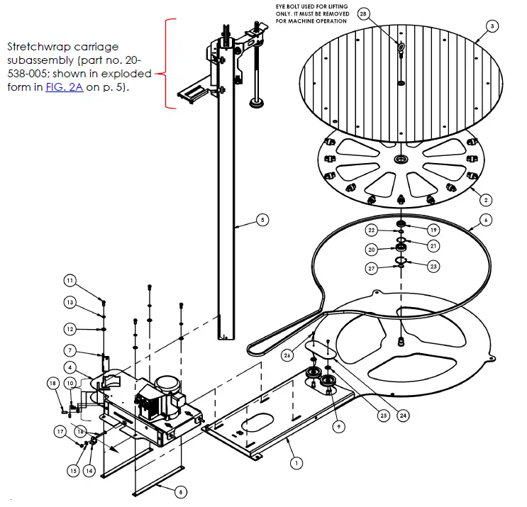
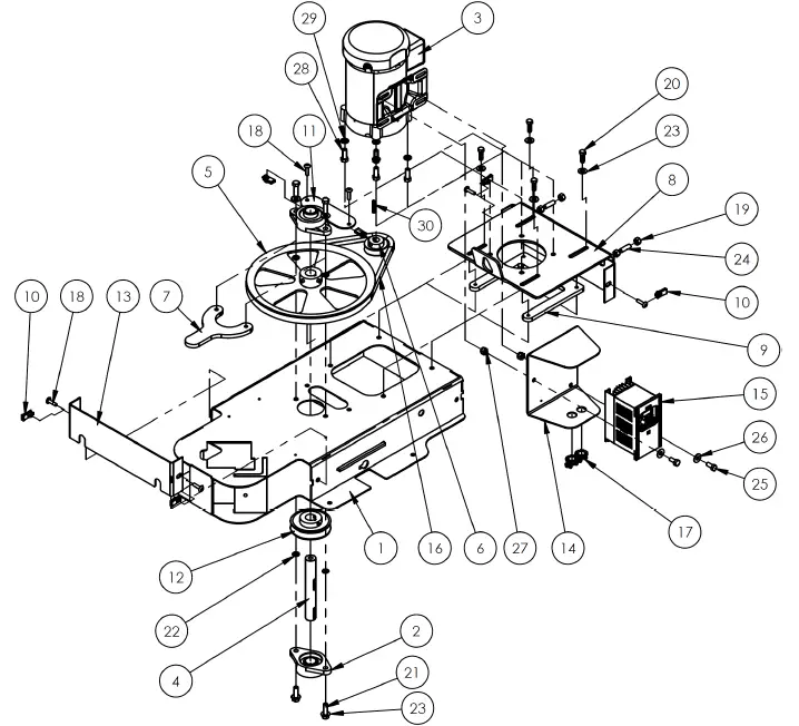
SWA-50 EXPLODED VIEW & BILL OF MATERIALS (20-006-116)
| Item | Part no. | Description | Qty. | Item | Part no. | Description | Qty. |
| 1 | 20-514-078 | WELDMENT, BASE FRAME | 1 | 15 | 33006 | FLAT WASHER,ZINC PLATED,USS, Ø5/16″ | 1 |
| 2 | 20-610-001 | SUB-ASSEMBLY, THRUST BEARING | 1 | 16 | 21265 | BOLT, CARRIAGE, GRADE A, 5/16-18UNC x 3 LG. ZINC PL | 1 |
| 3 | 20-513-098 | WELDMENT, DECK | 1 | 17 | 37021 | NYLON INSERT LOCK NUT, GRADE 2, ZINC FINISH, 5/16″-18 | 1 |
| 4 | 20-160-001 | SUB-ASSEMBLY, POWER-UNIT W/ SHEAVE | 1 | 18 | 25544 | POINT SOCKET SET SCREW, Ø3/8-16 x 1 1/4 LG. | 2 |
| 5 | 20-514-084 | SUB-ASSEMBLY, COUNTERBALANCED MAST, MANUAL | 1 | 19 | 20-110-001 | SINGLE ROW BALL BEARING, SHIELDED | 1 |
| 6 | 20-027-007 | BELT, B190 | 1 | 20 | 20-110-022 | BEARING, 6206 | 1 |
| 7 | 20-014-117 | FRAME, BAR, SQUEEZE | 1 | 21 | 20-117-001 | INTERNAL RETAINING RING, Ø 2″ | 1 |
| 8 | 20-113-024 | SPACER, PLATE | 2 | 22 | 20-117-003 | EXTERNAL RETAINING RING, 1″ DIA SHAFT | 1 |
| 9 | 20-027-012 | BELT IDLER | 2 | 23 | 20-117-005 | INTERNAL RETAINING RING, Ø2-7/16″ | 1 |
| 10 | 36106 | HEX NUT, GRADE A, ZINC PLATED, 3/8-16 | 4 | 24 | 20-024-025 | COVER PLATE, IDLER ACCESS | 1 |
| 11 | 11105 | HEX BOLT, GRADE A, ZINC PLATED, 3/8″-16X1″ | 4 | 25 | 33090 | WASHER, FLAT, SAE, 5/8 | 2 |
| 12 | 33008 | FLAT WASHER, LOW CARBON, USS, ZINC PLATED, 3/8″ | 4 | 26 | 11001 | HEX BOLT, GRADE A, ZINC PLATED, 1/4″-20 X 1/2″ | 2 |
| 13 | 33622 | SPLIT LOCK WASHER, CARBON STEEL, MEDIUM ZINC FINISH, 3/8″ | 4 | 27 | 68021 | EXTERNAL RETAINING RING, PHOSPHATE FINISH, 1-1/8″ | 1 |
| 14 | 20-016-096 | BRACKET TENSIONING FORMED | 1 | 28 | 99-145-190 | SPECIALTY HARDWARE, EYE BOLT, 1/2″ DIA. X | 1 |
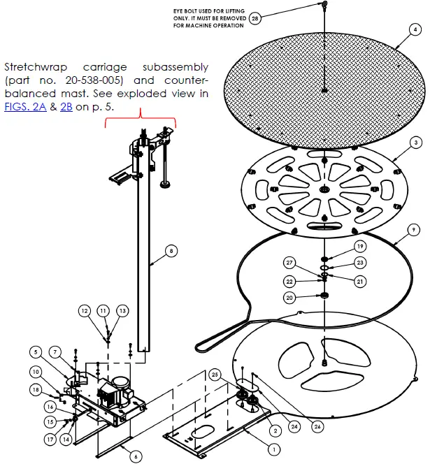
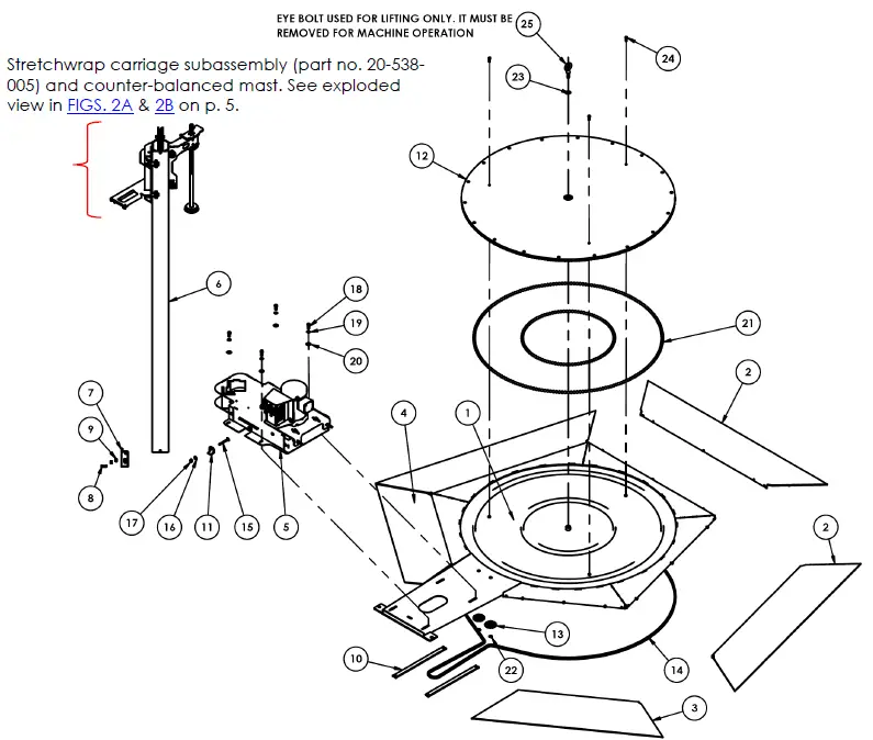
STRETCHWRAP CARRIAGE SUBASSEMBLY EXPLODED VIEW & BILL OF MATERIALS
| Item | Part no. | Description | Qty. |
| 1 | 20-514-080 | Weldment, carriage frame | 1 |
| 2 | 20-145-010 | Specialty hardware, clamp, wrap, mounting | 1 |
| 3 | 21-113-021 | Spacer, bearing shaft | 8 |
| 4 | 20-110-006 | Roller bearing | 8 |
| 5 | 11109 | 3/8in. – 16 x 11/2in. HHCS #2 zinc— plated bolt | 4 |
| 6 | 11111 | 3/8in. – 16 x 2in. HHCS #2 zinc—plated bolt | 4 |
| 7 | 20-040-001 | Lever, brake release, formed | 1 |
| 8 | 21-113-020 | Spacer, bearing | 4 |
| 9 | 20-113-023 | Spacer | 1 |
| 10 | 20-146-008 | Spring, compression spring | 1 |
| 11 | 99-112-006 | Pin, clevis | 1 |
| 12 | 33008 | 3/8in. USS zinc-plated flat washer | 10 |
| 13 | 37024 | 3/8in. Nylock insert nut | 9 |
| 14 | 64076 | 1/8in. x 1in. zinc-plated cotter pin | 1 |
| 15 | 20-537-018 | Brake pad assembly | 1 |
| 16 | 11105 | 3/8in. – 16 x 1in. HHCS #2 zinc-plated bolt | 1 |
| 17 | 33622 | 3/8in. zinc-plated lock washer | 1 |
| 18 | 65078 | 1/8in. x 11/2in. zinc-plated cotter pin | 1 |
MANUAL COUNTERBALANCED MAST SUBASSEMBLY EXPLODED VIEW & BILL OF MATERIALS (20-514-084)

| Item | Part no. | Description | Qty. |
| 1 | 20-538-005 | Subassembly, carriage | 1 |
| 2 | 20-514-082 | Subassembly, mast, manual | 1 |
| 3 | 26333 | Shoulder screw 0.375in. x 1.5in. | 1 |
| 4 | 33008 | 3/8in. USS zinc-plated flat washer | 2 |
| 5 | 37024 | 3/8in. Nylock insert nut | 1 |
| 6 | 20-027-001 | Pulley, counterweight | 1 |
| 7 | 20-145-019 | Specialty hardware, swage sleeve | 2 |
| 8 | 20-145-018 | Specialty hardware, cable | 1 |
| 9 | 28-014-179 | Cast, counterweight (SWA-48) | 1 |
| 10 | 20-620-001 | Weldment, specialty hardware, rod tension wing nut | 1 |
| 11 | 20-113-003 | 7/8in. fiber washer | 2 |
| 12 | 20-014-005 | Frame, tube retainer, (top) | 1 |
| 13 | 68061 | 15/8in. retainer ring | 1 |
| 14 | 20-014-006 | Tube, retainer, (bottom) | 1 |
| 15 | 20-110-002 | Bearing, ball, 3/4 bore, metal shield | 1 |
| 16 | 20-014-116 | Frame, rod, wrap retainer | 1 |
| 17 | 20-113-022 | Spacer, lock | 1 |
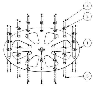
THRUST BEARING SUBASSEMBLY EXPLODED VIEW & BILL OF MATERIALS (20-610-001)
| Item | Part no. | Description | Qty. |
| 1 | 20-610-003 | Weldment, thrust bearing plate | 1 |
| 2 | 20-027-011 | Load roller | 16 |
| 3 | 26327 | Shoulder screw 0.375in. x 0.5in. | 32 |
| 4 | 37021 | 5/16in. – 18 zinc-plated #2 nylon lock nut | 32 |
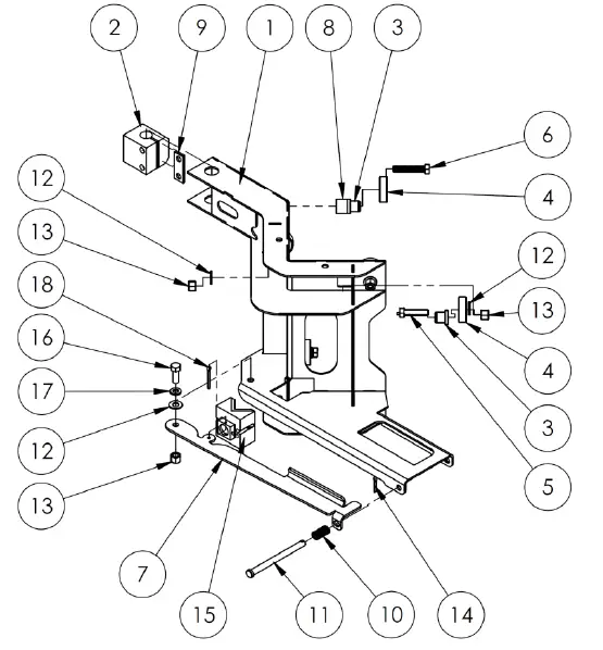
POWER UNIT SUBASSEMBLY WITH SHEAVE EXPLODED PARTS DIAGRAM & BILL OF MATERIALS (20-160-001)
| Item | Part no. | Description | Qty | Item | Part no. | Description | Qty |
| 1 | 20-514-099 | Weldment, frame, subassembly | 1 | 16 | 20-027-008 | Belt, B40 | 1 |
| 2 | 20-110-014 | Flange, 2 bolt, 1in. inner diameter | 2 | 17 | 99-034-037 | Accessories, electrical, Romex 0.375in. | 2 |
| 3 | 20-135-004 | Motor 1/2 HP, 3 PH, 1725 RPM, 230/460V, 60 Hz | 1 | 18 | 29185 | Screw, machine, truss head | 6 |
| 4 | 20-112-015 | Shaft pin, 1in. outer diameter | 1 | 19 | 36106 | 3/8in. – 16 zinc-plated hex nut | 4 |
| 5 | 20-027-010 | Sheave, 12in., 1in. hub | 1 | 20 | 11055 | 5/16in. – 18 x 1in. HHCS zinc-plated #2 bolt | 4 |
| 6 | 20-027-009 | Sheave 5/8in. inner diameter x 2 in. outer diameter | 1 | 21 | 11107 | 3/8in. – 16 x 11/4in. HHCS zinc-plated #2 bolt | 4 |
| 7 | 20-110-013 | Bearing, mount, upper | 1 | 22 | 33620 | 5/16in. zinc-plated lock washer | 4 |
| 8 | 20-016-085 | Bracket, motor, mounting plate | 1 | 23 | 33008 | 3/8in. USS zinc-plated flat washer | 8 |
| 9 | 20-016-084 | Bracket, motor, mounting plate | 1 | 24 | SSFLATSKT 0.375-16×1.25-HX-N | 2 | |
| 10 | 0162854 | U-spring, threaded nut | 6 | 25 | 11052 | 5/16in. – 18 UNC x 3/4in. HHCS screw | 2 |
| 11 | 20-024-023 | Plate cover, bearing | 1 | 26 | 33006 | 5/16in. USS zinc-plated flat washer | 2 |
| 12 | 20-042-019 | Sheave, drive | 1 | 27 | 37021 | 5/16in. – 18 #2 zinc-plated Nylon lock nut | 2 |
| 13 | 20-024-022 | Guard, end, formed | 2 | 28 | 11105 | 3/8in. – 16 x 1in. HHCS #2 zinc-plated bolt | 4 |
| 14 | 20-016-053 | Bracket, mounting | 1 | 29 | 33622 | 3/8in. zinc-plated lock washer | 4 |
| 15 | 20-029-006 | Accessories, electrical, delta controller | 1 | 30 | 99-130-001 | Pin, keystock | 1 |
SWA-70 EXPLODED VIEW (20-006-118)
| Item | Part no. | Description | Qty. | Item | Part no. | Description | Qty. |
| 1 | 20-514-079 | WELDMENT, BASE FRAME | 1 | 15 | 33006 | FLAT WASHER,ZINC PLATED,USS, Ø5/16″ | 1 |
| 2 | 20-027-012 | BELT IDLER | 2 | 16 | 21265 | BOLT, CARRIAGE, GRADE A, 5/16-18UNC x 3 LG. ZINC PL | 1 |
| 3 | 20-610-002 | SUB-ASSEMBLY, THRUST BEARING | 1 | 17 | 37021 | NYLON INSERT LOCK NUT, GRADE 2, ZINC FINISH, 5/16″-18 | 1 |
| 4 | 20-513-100 | WELDMENT, DECK | 1 | 18 | 25544 | POINT SOCKET SET SCREW, Ø3/8-16 x 1 1/4 LG. | 2 |
| 5 | 20-160-001 | SUB-ASSEMBLY, POWER-UNIT W/ SHEAVE | 1 | 19 | 20-110-001 | SINGLE ROW BALL BEARING, SHIELDED | 1 |
| 6 | 20-113-024 | SPACER, PLATE | 2 | 20 | 20-110-022 | BEARING, 6206 | 1 |
| 7 | 20-014-117 | FRAME, BAR, SQUEEZE | 1 | 21 | 20-117-001 | INTERNAL RETAINING RING, Ø 2″ | 1 |
| 8 | 20-514-084 | SUB-ASSEMBLY, COUNTERBALANCED MAST, MANUAL | 1 | 22 | 20-117-003 | EXTERNAL RETAINING RING, 1″ DIA SHAFT | 1 |
| 9 | 20-027-014 | BELT, B245 | 1 | 23 | 20-117-005 | INTERNAL RETAINING RING, Ø2-7/16″ | 1 |
| 10 | 36106 | HEX NUT, GRADE A, ZINC PLATED, 3/8-16 | 4 | 24 | 20-024-025 | COVER PLATE, IDLER ACCESS | 1 |
| 11 | 11105 | HEX BOLT, GRADE A, ZINC PLATED, 3/8″- 16 X 1″ | 4 | 25 | 33090 | WASHER, FLAT, SAE, 5/8 | 2 |
| 12 | 33008 | FLAT WASHER, LOW CARBON, USS, ZINC PLATED, 3/8″ | 4 | 26 | 11001 | HEX BOLT, GRADE A, ZINC PLATED, 1/4″-20 X 1/2″ | 2 |
| 13 | 33622 | SPLIT LOCK WASHER, CARBON STEEL, MEDIUM ZINC FINISH, 3/8″ | 4 | 27 | 68021 | EXTERNAL RETAINING RING, PHOSPHATE FINISH, 1-1/8″ | 1 |
| 14 | 20-016-096 | BRACKET, TENSIONING, FORMED | 1 | 28 | 99-145-190 | SPECIALTY HARDWARE, EYE BOLT, 1/2″ DIA. X 1 1/2″ SHANK | 1 |
SWA-51-AR5 EXPLODED VIEW (20-006-188)
| Item | Part no. | Description | Qty. | Item | Part no. | Description | Qty. |
| 1 | 20-514-135 | WELDMENT, FRAME | 1 | 14 | 20-042-034 | #35 CHAIN | 1 |
| 2 | 20-514-136 | WELDMENT, APPROACH RAMP | 3 | 15 | 21265 | BOLT, CARRIAGE, GRADE A, 5/16-18UNC x 3 LG. ZINC PL | 1 |
| 3 | 20-514-137 | WELDMENT, APPROACH RAMP | 1 | 16 | 33006 | FLAT WASHER,ZINC PLATED,USS, Ø5/16″ | 1 |
| 4 | 20-514-138 | WELDMENT, APPROACH RAMP | 1 | 17 | 37021 | NYLON INSERT LOCK NUT, GRADE 2, ZINC FINISH, 5/16″-18 | 1 |
| 5 | 20-160-002 | SUB-ASSEMBLY, POWER-UNIT W/ SPROCKET | 1 | 18 | 11105 | HEX BOLT, GRADE A, ZINC PLATED, 3/8″- 16 X 1″ | 4 |
| 6 | 20-514-084 | SUB-ASSEMBLY, COUNTERBALANCED MAST, MANUAL | 1 | 19 | 33622 | SPLIT LOCK WASHER, CARBON STEEL, MEDIUM ZINC FINISH, 3/8″ | 4 |
| 7 | 20-014-117 | FRAME, BAR, SQUEEZE | 1 | 20 | 33008 | FLAT WASHER, LOW CARBON, USS, ZINC PLATED, 3/8″ | 4 |
| 8 | 25544 | POINT SOCKET SET SCREW, Ø3/8-16 x 1 1/4 LG. | 2 | 21 | 20-110-004 | BEARING, BALL | 300 |
| 9 | 36106 | HEX NUT, GRADE A, ZINC PLATED, 3/8-16 | 4 | 22 | 68013 | Ø5/8 EXTERNAL RETAINING RING | 2 |
| 10 | 20-113-024 | SPACER, PLATE | 2 | 23 | 20-117-003 | EXTERNAL RETAINING RING, 1″ DIA SHAFT | 1 |
| 11 | 20-016-096 | BRACKET, TENSIONING, FORMED | 1 | 24 | 11005 | BOLT, GRADE A, Ø1/4-20 UNC x 1 LG, HHCS #2 Z-PLATED | 3 |
| 12 | 20-513-052 | WELDMENT, DECK AND SPROCKET | 1 | 25 | 99-145-190 | SPECIALTY HARDWARE, EYE BOLT, 1/2″ DIA. X 1 1/2″ SHANK | 1 |
| 13 | 20-042-033 | SPROCKET, IDLER ASSEMBLY | 2 |
ELECTRICAL SYSTEM DIAGRAM
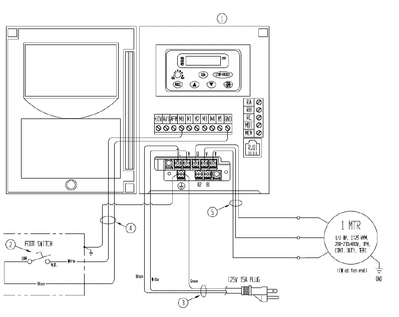
| Item | Part no. | Description | Quantity |
| 1 | VFD004S11B | Delta control, freq. variable, AC | 1 |
| 2 | 20-522-001 | Switch, single foot, 108in. cord | 1 |
| 3 | 01-033-015 | Cord, 14/3, 9in. with 15A molded plug | 1 |
| 4 | N/A | Cable, 18/3, pltc gray | 1 |
| 5 | N/A | Cable, 14/3, sjtd, yellow | 1 |
Static electricity is produced when items are stretch wrapped. The static effect can intensify in dry air. To reduce the effects of static electricity on the wrapping machine, always ground the control to the frame of the machine. If significant static electricity is experienced, bond the frame of the machine to a driven ground rod (see National Electrical Code for details of driven grounding electrodes).
POWERED MAST ELECTRICAL CIRCUIT DIAGRAM

DELTA MOTOR SPEED CONTROLLER
To change the controller parameters, use the buttons on the keypad to select the desired settings (see “Speed controller parameter settings” table below)
- PROG/DATA: press the “PROG DATA” button to initiate program mode; then the following screen will appear

- This screen indicates which parameter number is selected (see table below), which in this case is parameter 0. Press the up or down arrow button to select the desired parameter number (0; 1; 2; 6; or 7). Press the PROG/DATA button again to reveal the second set of numbers (on the right side of the dash in the “parameter” column of the table below). Use the arrow buttons to select the desired number. After completing the desired combination of numbers, press the MODE button twice to return to the home screen.
- MODE: press the MODE button to display information about the status of the drive. Successively pressing the MODE button displays different information. For example, pressing the MODE button 3 times displays the current speed (in rpm’s) of the turntable. (E.g. 12rpm displays as “u 12”.)
- Arrow keys: press the up or down buttons to scroll through different parameters. Press the up or down arrow key quickly to change parameter settings in single unit increments.
- The following table indicates the controller settings for each model that are required to achieve a minimum rotation speed of 3rpm and an upper rotation speed of 12rpm:
| Model | Parameter | Setting | Parameter | Setting |
| SWA-50 | 1-08 | d10 | 1-07 | d40 |
| SWA-70 | 1-08 | d8 | 1-07 | d35 |
| SWA-51-AR5 | 1-08 | d20 | 1-07 | d65 |
Speed controller parameter settings
| Parameter | Description of parameter | Setting | Description of setting |
| 0-03 | Start-up display selection | d2 | Display the content of user-defined unit |
| 0-05 | User defined coefficient K | d0.3 | Scales frequency so display shows approximate turntable rpm |
| 1-02 | Maximum output voltage | d255 | Sets maximum voltage to motor |
| 1-07 | Upper bound of frequency | d65 | Sets maximum rotation speed with speed knob turned fully clockwise (~11 rpm) |
| 1-08 | Lower bound of frequency | d15 | Sets minimum rotation speed with speed knob turned fully counterclockwise (~3 rpm) |
| 1-09 | Acceleration time | d10* | Time to accelerate motor to maximum output frequency in seconds |
| 1-15 | Auto accelerate/decelerate | d0* | Allows for linear acceleration of motor |
| 1-16 | S-curve in acceleration | d 7 | Determines how smoothly drive accelerates |
| 2-00 | Source of frequency command | d 3 | Allows turntable speed to be controlled by knob on keypad |
| 2-01 | Source of operation command | d 1 | Makes drive turn on external foot switch |
| 2-02 | Stop method | d 1 | Allows turntable to coast to stop |
| 6-02 | Over-current stall prevention limit | d 150 | Sets maximum motor current as percentage of rated output |
| 6-03 | Over-torque detection mode | d3 | Detection enabled during acceleration & continues until Continuous Output Time Limit |
| 6-04 | Over-torque detection level | d 200 | Sets maximum output torque as percentage of rated output |
| 6-05 | Continuous output time limit | d10 | Determines how long (in seconds) drive runs after over-torque detected |
| 7-00 | Motor rated current | d 120 | Establishes maximum output current as percentage of rated output |
| 7-01 | Motor no-load current | d 75 | Sets motor slip compensation |
| 7-02 | Torque compensation | d 10 | Sets maximum startup torque |
INSTALLATION
NOTE: Record the maximum turntable rotation speed when the machine is first installed.
To install a ramp
- Position it as desired in relation to the wrapping machine. The ramp should not interfere with the turntable as it rotates;
- Fasten it to the ground with hardware as described in step 5 below through each anchor tab.
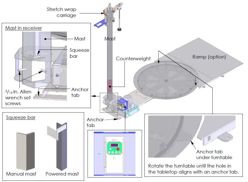
- Move the machine to the desired installation location. Install the machine only on an even, level surface.
- Lift the mast into the upright position. Insert the mast through the mast sockets with the stretch wrap carriage pointing towards the turntable.
- Insert the squeeze bracket into the gap between the mast and the socket as shown below; then tighten the set screws against it using a 3/16in. Allen wrench. [NOTE: The mast will wobble due to plate flexion during use even with the squeeze angle firmly secured against the mast.]
- [Manual models] Manual wrapping machines counterbalance the combined weight of the wrapping material and the material carriage with a counterweight inside the mast. The machine is shipped with the carriage raised to the top of the mast and the counterweight at the bottom of the mast. The retaining screw (through the mast) prevents the counterweight from sliding inside the mast during the shipping process, but must be removed now. The head of the screw is located approximately 12 inches from the base of the mast.
- Fasten the machine to the floor with anchor bolts. There are 4 anchoring points: 2 in back and 2 under the turntable. Each of the 4 anchor tabs has a 5/8 in. hole for an anchor bolt. Your building engineer should evaluate the installation site and select 3/8 in. anchor bolts of a length appropriate for the location.
- Shim and grout under the frame.
- Connect the wrapping machine to an AC power source: Insert the turntable power cord into a 15A, 115 VAC receptacle.
- [Powered mast models] Powered mast models have 2 power cords: one for the turntable and another for the wrapping carriage. The 2 cords can either both be plugged into a power outlet, or be connected and plugged into an outlet. To connect the cords, plug the turntable power cord into the pigtail cord of the mast control enclosure; then plug the power cord for the mast into a 115 VAC receptacle.
- Test the powered functions
- Turntable rotation: press the foot pedal to initiate rotation. The turntable will rotate as long as the pedal is pressed.
- Delta speed controller: refer to the Delta operation manual.
- Powered mast models: raise and lower the stretch wrap carriage with the UP and DOWN buttons on the pendant (hand) controller. Confirm that the carriages moves smoothly and that both the upper and lower travel limit switches function properly.
STRETCH WRAP HOLDER ASSEMBLY
The wrap holder accommodates 10-20 inch rolls of stretch wrap.
Loading stretch wrap
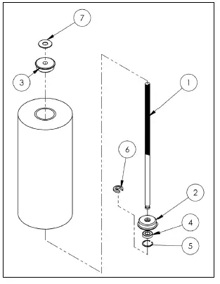
- Unwind the wing nut (A) sufficiently to remove the lock spacer (6) underneath the bottom retainer (2).
- Remove the lock spacer.
- Remove the retainer (5) and bearing (4).
- Remove the spent roll of stretch wrap and install a new roll.
- Reinstall the retainer (5) and secure it in place with the lock spacer (6).
- Tighten the wing nut (A) until the roll is snugly grasped between the tube retainers (2) and (3). Adjust the tightness of the wing nut to achieve the desired degree of material stretch—the material will stretch more the more tightly the roll is grasped.
Assembled stretch wrap holder
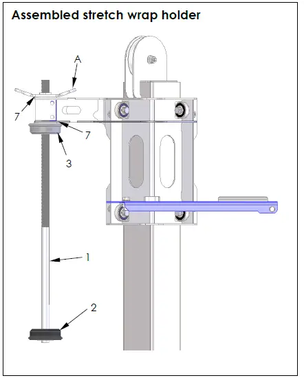
| Item | Part no. | Description | Quantity |
| 1 | 20-014-116 | Frame, rod, wrap retainer | 1 |
| 2 | 20-014-006 | Tube retainer (bottom) | 1 |
| 3 | 20-014-005 | Tube retainer (top) | 1 |
| 4 | 20-110-002 | Bearing, ball, 3/4 in., shield | 1 |
| 5 | 68061 | 15/8 in. retainer ring | 1 |
| 6 | 20-113-022 | Spacer, lock | 1 |
| 7 | 20-113-003 | 7/8 in. fiber washer | 1 |
| *8 | SRF-18 | 20in. plastic wrap (not included) | 1 |
BELT TENSIONING PROCEDURE
The wrapping machine uses 2 belts to rotate the turntable and the tension of each belt occasionally requires adjustment. For instance, if the turntable vibrates or rattles, the tension of the lower belt needs to be adjusted. Similarly, if the turntable drive motor (or the metal box that supports the motor) vibrates, the tension of the upper belt should be increased.
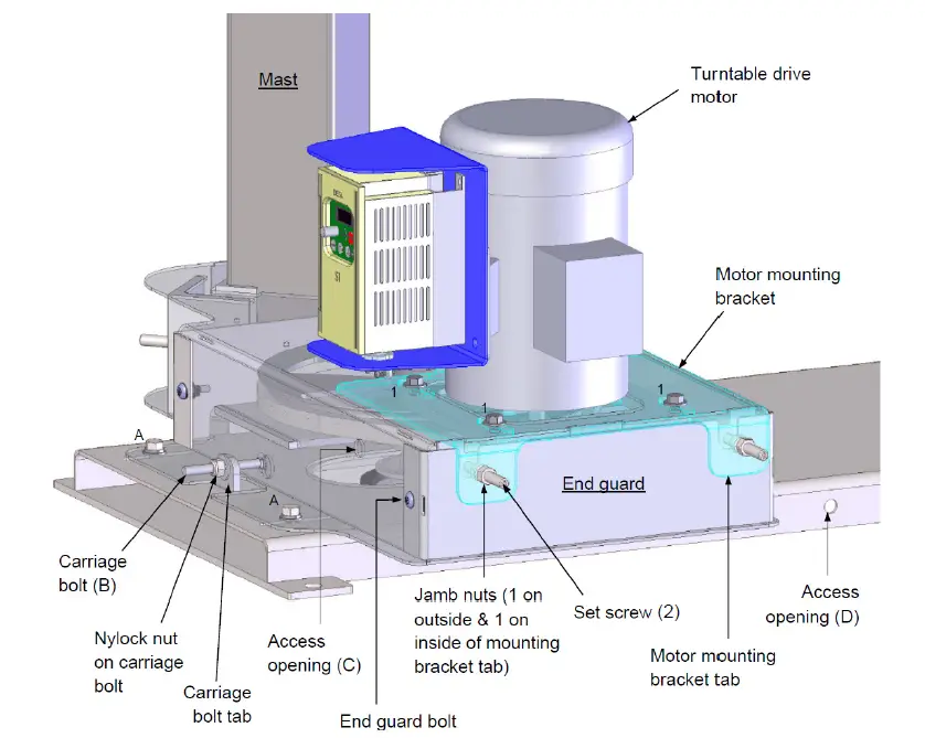
- Adjust the tension of the upper (small) belt.
- Loosen all four bolts (1) adequately to allow the motor mounting bracket to slide. [NOTE: Only three bolts are shown in the diagram above.]
- Loosen the jamb nuts on the set screws (2).
- Remove the end guard by removing both end guard bolts.
- Assess the adequacy of belt tension by doing the following:
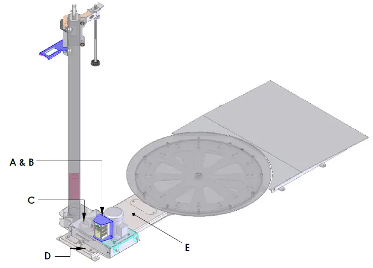
- Locate the access opening (C); then insert a metal rod approximately 3/8” x 10” long, into the access opening. The rod must have a smooth, flat end without sharp projections that might damage the belt.
- Locate the belt with the end of the rod. Lightly contact the belt at the point approximately halfway between the two pulleys. The rod should be perpendicular to the belt. Do not press the rod into the belt. Make a first mark on the rod that is flush with the top of the access opening (C). Make a second mark 1/8 in. above the first mark.
- Using a “pencil type” compression spring scale, measure the force required to push the rod 1/8 in., that is, the force required to move the rod inwardly so that the second mark is flush with the top of the opening (C).
- If necessary, adjust the tension of the belt. If the belt is new, the force measured by the spring scale should equal 16 lbs. After a belt is broken in, the force required should be between 8-12 lbs. To adjust belt tension, use a 3/16 in. Allen wrench to turn the set screws (2). To increase tension, turn the screws clockwise. To decrease tension, turn the screws counterclockwise. Turn both set screws the same amount.
- When belt tension is proper, retighten the jamb nuts on both set screws firmly against the bracket tabs; then reinstall the end guard and tighten all four of the motor mounting bracket bolts (1).
- Adjust the tension of the lower (large) belt.
- Loosen all 4 power unit subassembly bolts (A). [NOTE: Only 2 bolts are shown in the diagram; the other bolts are on the opposite side of the subassembly.]
- Locate the access opening (D); then insert a metal rod approximately 3/8” x 10” long, into the access opening. The rod must have a smooth, flat end without sharp projections that might damage the belt.
- Locate the belt with the end of the rod. Lightly contact the belt at the point approximately halfway between the two pulleys. The rod should be perpendicular to the belt. Do not press the rod against the belt. Make a first mark on the rod that is flush with the top of the access opening (D). Make a second mark 3/8 in. above the first mark.
- Using a “pencil type” compression spring scale, measure the force required to push the rod 3/8 in., that is, the force required to move the rod inwardly so that the second mark is flush with the top of the opening (D).
- If necessary, adjust the tension of the belt. If the belt is new, the force measured by the spring scale should equal 16 lbs. After a belt is broken in, the force required should be between 8-12 lbs. To increase tension, use a 9/16 in. wrench to turn the lock nut on carriage bolt (B) clockwise. To decrease tension, turn the nut counterclockwise.
- When belt tension is proper, retighten the lock nut firmly against the carriage bolt tab; then tighten all 4 power unit subassembly bolts (A).
- Loosen all 4 power unit subassembly bolts (A). [NOTE: Only 2 bolts are shown in the diagram; the other bolts are on the opposite side of the subassembly.]
USE INSTRUCTIONS
Standard SWA-50 and -70 wrapping machines must be used indoors. They are designed for moderate duty, intermittent cycling and will wrap loads weighing up to 4,000 pounds (1,818.2kg). The net weight of the pallet or skid and the items stacked on the pallet must not exceed 4,000 pounds. The load rating appears on Label 287, which is affixed to the machine as shown in the Labeling diagram. Place a load on the turntable
NOTICE: DO NOT drop loads onto the turntable, because shock loading will cause the load bearings to fail prematurely. DO NOT exceed the load rating; the drive system might be damaged or fail prematurely. To protect the load bearings, be careful when loading the turntable and slowly apply loads to the turntable. In particular, take care to not drop items on the table or to slam the tines of your fork lift on it.
Wrap the load
Standard model wrapping machines are equipped with a constant-pressure (dead man style) foot pedal control. As long as the pedal is pressed, the table will rotate. When the pedal is released, the turntable will coast to a stop.
Turntable rotation speed is adjustable. To increase or decrease the speed, turn the knob on the Delta controller (see p. 11) clockwise or counterclockwise, respectively. The number displayed on the screen of the control is the approximate number of revolutions per minute. The tension applied to the roll of stretch wrap determines how much the material stretches as it wraps around a load. Tension is also adjustable. To increase tension, turn the rod tension wing nut (item no. 1, on p. 13) clockwise. To decrease tension, turn the wing nut counterclockwise. To begin wrapping a load, set the tension to allow the wrap to easily pull off of the roll. Fix the end of the wrap to the load, for example by tying it to the pallet; then press the pedal control to rotate the turntable. Next, tighten the wing nut to achieve the desired material tension after wrapping the material around the load once or twice to prevent it from coming loose. To wrap the load, move the wrap holder assembly up and down as necessary to achieve the coverage desired for the load. Cover the entire load with 2-3 layers of wrapping material. To complete the wrapping process, cut (or tear) the material and press the end against the side of the load.
INSPECTIONS & MAINTENANCE
WARNING: DO NOT use the wrapping machine until all problems discovered during an inspection have been resolved.
Before each use, inspect the listed components
- Wiring: examine the wires for fraying and damage.
- Mast, turntable, and frame: Handrails: check each structure for bends, warps and cracks.
- Power transmission and control equipment (particularly the foot pedal): inspect each component and associated guards and cords for damage.
- Operate the wrapper: observe and listen to the machine as it operates for unusual noise or movement, or binding.
- Product labels: all labels should be readable and located as shown in the “Labeling diagram” on p. 17. If a label(s) is unreadable or missing, order a replacement.
NOTE: Label appearance and content is subject to change over time, and consequently, replacement labels might differ from labels shown in the manual supplied with the unit.
At least 1 time per month, inspect
- Electrical wiring: closely inspect wiring for regions of significant wear, cuts, frays, and other damage.
- Fasteners (hardware): check fasteners for looseness and damage. Tighten all loose fasteners; replace any that are damaged: Bolts, nuts, washers;
- Turntable drive belt: inspect the drive belt for significant wear and looseness. If the belt is significantly worn, replace the belt. Operate the turntable and compare the current maximum rotation speed with the speed recorded when the machine was first installed. If the top rotation speed is slower than the initial figure, adjust the tightness of the belt. See Belt tensioning procedure.
- Motor speed control: if the speed control enclosure is broken, then the drive should be replaced.
- Turntable: examine the turntable for significant wear and impact damage. Sharp projections might develop along the edge of the turntable. Sand or grind off all projections, burrs, etc.
- Load bearings: operate the turntable and listen for scraping sounds. If the turntable is noisy while it rotates, replace the load bearings.
- Turntable main bearing: the top of the turntable should be parallel to the supporting frame; it should not wobble (press down and pull up on the edge of the turntable).
- Carriage slides: inspect the slides for excessive wear.
- Fiber washer (see item no): check the fiber washer of the (shrink wrap) material holder. Make sure that it is not significantly worn.
- Anchoring points: check each of the anchor bolts and the concrete. The machine should be solidly fixed to the floor. Tighten bolts, if necessary. Also inspect the concrete around each bolt. It should not be cracked, chipped, etc.
- Labels: confirm that all labels are in place, undamaged, and readable. See Labeling diagram on p. 17
- Overall condition of wrapping machine: the structure should be clean, square and rigid, and free of rust and corrosion. Remove dirt and debris. Do not use the machine if the base is excessively rusted or corroded.
LABELING DIAGRAM
Label content and location are subject to change so your product might not be labeled exactly as shown. Replace all labels that are damaged, missing, or not easily readable (e.g. faded). To order replacement labels, contact the technical service and parts department online at http://www.vestilmfg.com/parts_info.htm. Alternatively, you may request replacement parts and/or service by calling (260) 665-7586 and asking the operator to connect you to the Parts Department.
(Label 221)
DANGER: ELECTRICAL SHOCK
- Shut power off and consult owners manual before working on this equipment.
(Label 325)
NOTICE
- POWER SUPPLY: 115 V/1 Phase/60 HZ
- CONTROL VOLTAGE: 115V AC
(Label 1153)
- MODEL: ……………………………
- WEIGHT: ……………………………
- CAPACITY: ……………………………
- SERIAL: ……………………………
(Label 204)
WARNING: SECURE FRAME TO FLOOR
(Label 824)
DANGER: To avoid bodily injury stand clear while in motion.
TROUBLESHOOTING
| Issue | Possible Cause | Corrective Action |
| 1) Turntable does not rotate | No power supply voltage | Check outlet for 115V power. If outlet lacks |
| power, determine cause of power loss before | ||
| restoring power to the wrapping machine. | ||
| [NOTE: If turntable power cord is plugged into | ||
| the pigtail cord of the powered mast, | ||
| confirm that powered mast cord is plugged | ||
| into a wall socket.] | ||
| Speed control on lowest | Increase turntable speed using knob on | |
| setting | Delta motor speed controller. | |
| No signal from pedal control | Check continuity of foot pedal and the | |
| cable connected to it. | ||
| Motor controller fault or | Check the display on the Delta motor speed | |
| defective motor controller | controller for a fault code. If a fault code is | |
| displayed, contact Vestil Manufacturing | ||
| (phone number on cover of this manual). | ||
| Belt is broken or slipping | If fan of drive motor spins but table does not | |
| rotate, release the foot pedal; then inspect | ||
| the belts. | ||
| Turntable cannot | Belt is broken or slipping | If fan of drive motor spins but table does not |
| rotate without assistance, | rotate, release the foot pedal; then inspect | |
| rotates more slowly while | the belts. | |
| loaded, or does not | ||
| achieve set speed | ||
| Mast motor or control | Excessive voltage drop to | Check power supply for adequacy. Check |
| enclosure hums, chatters, | motor due to: | incoming voltage while motor runs. If the |
| or buzzes, and the stretch | voltage is too low, correct by | |
| wrap holder moves slowly |
|
|
| or not at all. |
|
|
|
| |
| Damaged mast or stretch | Examine mast and holder for damage or | |
| wrap holder | excessive wear. | |
| Low control voltage or bad | Confirm 24VAC at transformer secondary. | |
| connection in control circuit | Examine all wiring and connections in the | |
| mast for looseness, etc. | ||
| Powered stretch wrap | Low control voltage or bad | Confirm 24VAC at transformer secondary. |
| holder does not respond | connection in control circuit | Examine all wiring and connections in the |
| to commands (UP and | mast for looseness, etc. | |
| DOWN) | Blown transformer fuse | Test with meter; replace if bad (replace with |
| same fuse type and ampere rating) | ||
| No power supply voltage | Check outlet for 115V power. If outlet lacks | |
| power, determine cause of power loss before | ||
| restoring power to the wrapping machine. | ||
| [NOTE: If turntable power cord is plugged into | ||
| the pigtail cord of the powered mast, | ||
| confirm that powered mast cord is plugged | ||
| into a wall socket.] | ||
| Mast limit switch engaged or | Inspect and test switch, Replace if bad. | |
| malfunctioning | ||
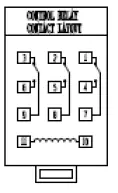
| Control relay 1 CR contact is | Examine contact. Clean contact or replace | |
| burnt | relay as necessary. | |
| Control relay 1 CR is loose | Verify that the relay is firmly in place. | |
| Powered mast stretch | Control relay 2 CR is loose | Confirm that the relay is firmly in place |
| wrap holder rises on | CR 2 is defective | Examine and test 2 CR. Replace if necessary. |
| command but does not | Bad connection in control | Test all parts of circuit with meter |
| lower | circuit | |
| Physical blockage in mast | Determine cause of blockage and remove it | |
LIMITED WARRANTY
Vestil Manufacturing Corporation (“Vestil”) warrants this product to be free of defects in material and workmanship during the warranty period. Our warranty obligation is to provide a replacement for a defective, original part covered by the warranty after we receive a proper request from the Warrantee (you) for warranty service.
Who may request service?
Only a warrantee may request service. You are a warrantee if you purchased the product from Vestil or from an authorized distributor AND Vestil has been fully paid.
Definition of “original part”?
An original part is a part used to make the product as shipped to the Warrantee.
What is a “proper request”?
A request for warranty service is proper if Vestil receives: 1) a photocopy of the Customer Invoice that displays the shipping date; AND 2) a written request for warranty service including your name and phone number. Send requests by one of the following methods
US Mail
- Vestil Manufacturing Corporation
- 2999 North Wayne Street, PO Box 507 Angola, IN 46703
- Fax: (260) 665-1339
- Phone: (260) 665-7586
- Email: [email protected]
Enter “Warranty service request” in subject field.
In the written request, list the parts believed to be defective and include the address where replacements should be delivered. After Vestil receives your request for warranty service, an authorized representative will contact you to determine whether your claim is covered by the warranty. Before providing warranty service, Vestil will require you to send the entire product, or just the defective part (or parts), to its facility in Angola, IN.
What is covered under the warranty?
The warranty covers defects in the following original, dynamic parts: motors, hydraulic pumps, motor controllers, and cylinders. It also covers defects in original parts that wear under normal usage conditions (“wearing parts”), such as bearings, hoses, wheels, seals, brushes, and batteries.
How long is the warranty period?
The warranty period for original dynamic components is 1 year. For wearing parts, the warranty period is 90 days. Both warranty periods begin on the date Vestil ships the product to the Warrantee. If the product was purchased from an authorized distributor, the periods begin when the distributor ships the product. Vestil may, at its sole discretion, extend a warranty period for products shipped from authorized distributors by up to 30 days to account for shipping time.
If a defective part is covered by the warranty, what will Vestil do to correct the problem?
Vestil will provide an appropriate replacement for any covered part. An authorized representative of Vestil will contact you to discuss your claim.
What is not covered by the warranty?
The Warranty (you) are responsible for paying labor costs and freight costs to return the product to Vestil for warranty service.
Events that automatically void this Limited Warranty
- Misuse;
- Negligent assembly, installation, operation or repair;
- Installation/use in corrosive environments;
- Inadequate or improper maintenance;
- Damage sustained during shipping;
- Collisions or other accidents that damage the product;
- Unauthorized modifications: Do not modify the product IN ANY WAY without first receiving written authorization from Vestil.
Do any other warranties apply to the product?
Vestil Manufacturing Corp. makes no other express warranties. All implied warranties are disclaimed to the extent allowed by law. Any implied warranty not disclaimed is limited in scope to the terms of this Limited Warranty. Vestil makes no warranty or representation that this product complies with any state or local design, performance, or safety code or standard. Noncompliance with any such code or standard is not a defect in material or workmanship.
Vestil Manufacturing Co.
- 2999 North Wayne Street, P.O. Box 507, Angola, IN 46703
- Telephone: (260) 665-7586
- Toll-Free: (800) 348-0868
- Fax: (260) 665-1339
- Web: www.vestilmfg.com
Copyright 2021 Vestil Manufacturing Corp.


