![]() CR50 Thermostat Controller
CR50 Thermostat Controller
 Instruction Manual
Key to symbols and safety instructions
Explanation of symbols
Warning symbols
Keywords at the start of a warning indicate the type and seriousness of the ensuing risk if measures to prevent the risk are not taken.
The following keywords are defined and can be used in this document:
DANGER:
DANGER indicates a situation that will result in severe injury or death.
WARNING:
WARNING indicates a situation that could result in severe injury or death.
CAUTION:
CAUTION indicates a situation that could result in minor to medium injury.
NOTICE:
NOTICE indicates a situation that could result in damage to property or equipment.
Important information
The info symbol indicates important information where there is no risk to people or property.
General safety instructions
Notice for the target group
These installation instructions are intended for plumbers, heating engineers and electricians. All instructions must be observed. Failure to comply with instructions may result in material damage and personal injury, including possible loss of life.
- Read the installation instructions (heat source, heating controller, etc.) before installation.
- Observe the safety instructions and warnings.
- Observe national and regional regulations, technical rules and guidelines.
Determined use
- Only use the product to control solar heating systems in single-family homes or apartment buildings.
Any other use is considered inappropriate. We take no responsibility for damage caused through incorrect use.
Electrical work
Electrical work must only be carried out by a qualified electrician.
- Before starting electrical work:
– Isolate the mains electrical supply and secure against reconnection.
– Using suitable means, test that the mains voltage is disconnected. - Never connect the product to mains voltage.
- Also observe the connection diagrams of other system components.
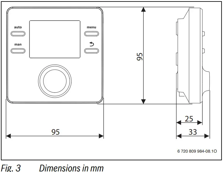
Product information
The CR 50 user interface is a control unit without an outdoor temperature sensor.
Information on energy efficiency (ERP Directive) can be found in the operating instructions.
Product description
The user interface is used to control a heating circuit without mixer and a DHW tank charging circuit for water heating directly at the heat source.
The user interface is not suitable for connecting the DHW cylinder behind a low loss header.
The user interface is installed in a suitable living space.
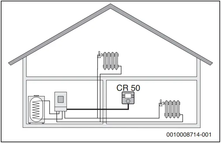
Fig. 1 Example of a heating system with one heating zone and a CR50 as controller (single-family home)
Scope of delivery
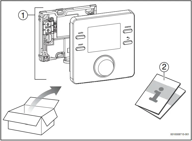
Fig. 2 Scope of delivery
- User interface
- Technical documentation
Technical data
| Rated voltage | 8 … 16 V DC (2-wire BUS/EMS 2 and Open Them) |
| Rated current | 5 … 23 mA (2-wire BUS/EMS 2 and Open Term) |
| BUS interface | 2-wire BUS, EMS 2, Panther |
| Control range | 5 … 30 °C |
| permissible ambient temperature | 0 °C … 50 °C |
| Power reserve | ³ 4 h |
| Protection class | III |
| IP-Rating | IP20 |
Table 1 Technical data
Temperature sensor characteristics
| °C | Ω | °C | Ω | °C | Ω | °C | Ω |
| 8 | 25065 | 32 | 9043 | 56 | 3723 | 80 | 1704 |
| 14 | 19170 | 38 | 7174 | 62 | 3032 | 86 | 1421 |
| 20 | 14772 | 44 | 5730 | 68 | 2488 | – | – |
| 26 | 11500 | 50 | 4608 | 74 | 2053 | – | – |
Table 2 Resistance values for flow and hot water temperature sensors
2.5 Applicability of the technical documentation
Information in the technical documentation about heat sources, heating controllers or the BUS apply also to the present user interface.
2.6 Additional accessories
No other BUS modules and user interfaces are possible in the system with the CR 50.
Combination is not possible with the following products: FR…, FW…, TR…, TF…, TA…
Installation
DANGER:
Life-threatening danger from electrical shock!
- Before installing this product:
Disconnect the heat source and all other BUS nodes from the mains voltage across all poles.
Installation location
This user interface is intended only for wall-mounted installation.
Do not install in the heat source or in wet areas.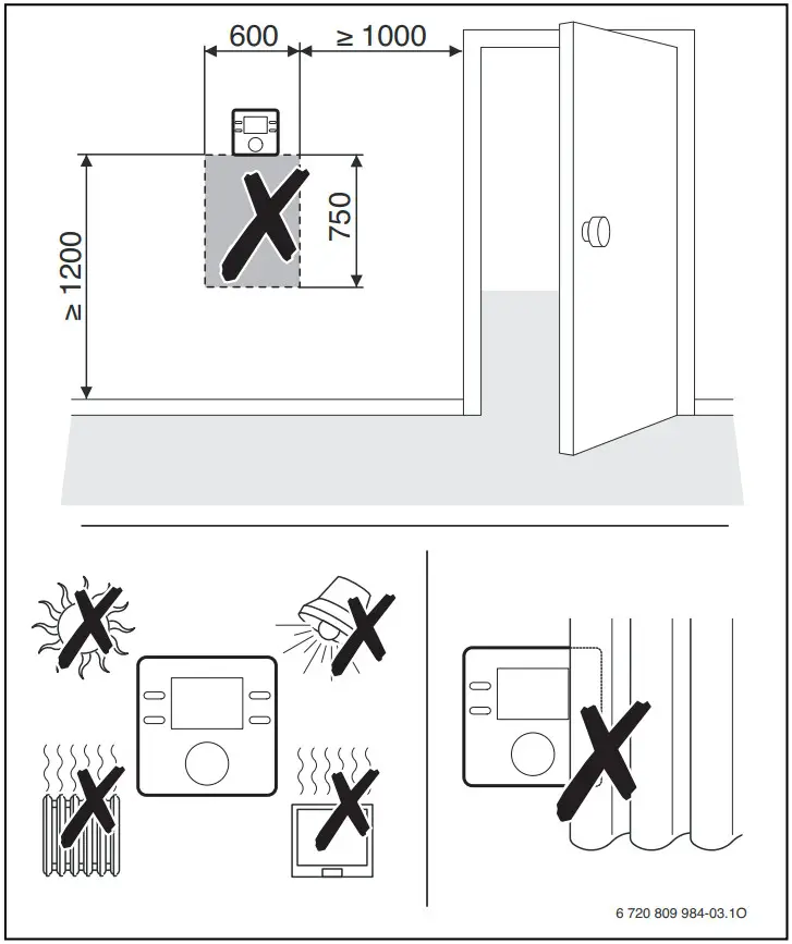
Fig. 4 Installation location in the reference room
Installation
Electrical connection
Power is supplied to the user interface via the BUS cable. The wires are insensitive to polarity.
If the maximum total length of the BUS interfaces between all BUS nodes is exceeded or the BUS system has a ring structure, commissioning of the system is not possible.
Maximum total length of BUS interfaces:
- 50 m at 0.50 mm conductor cross-section 2
- 300 m at 1.50 mm conductor cross-section.
- To avoid inductive interference: Make sure all low-voltage cables are routed separately from mains voltage cables (min. clearance 100 mm).
- In the case of external inductive interferences (e.g. from photovoltaic systems), use shielded cables (e.g. LIYCY) and earth the shield on one side. Connect the shield to the building’s earthing system, such as to a free earth conductor terminal or water pipe.
- Establish a BUS connection to the heat source.
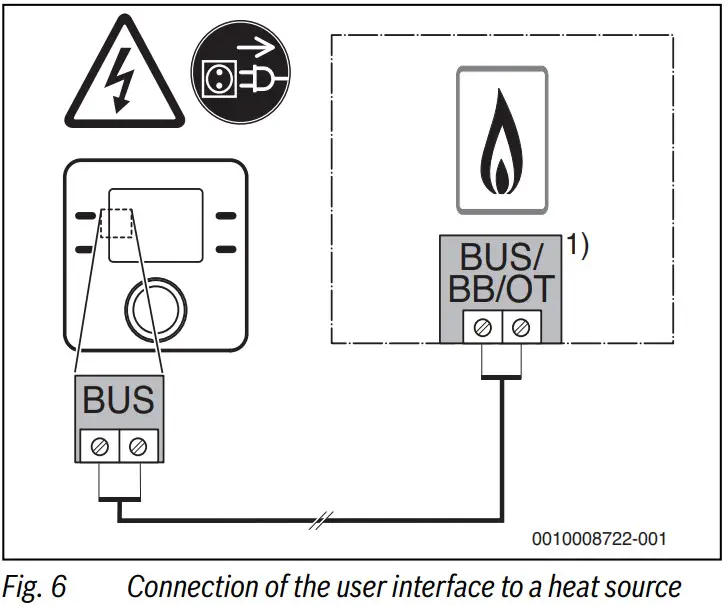
1) Terminal identification:
On heat sources with an Open Term BUS system: OT
On heat sources with a BUS system EMS 2 ABBAS
On heat sources with a 2-wire BUS: BB
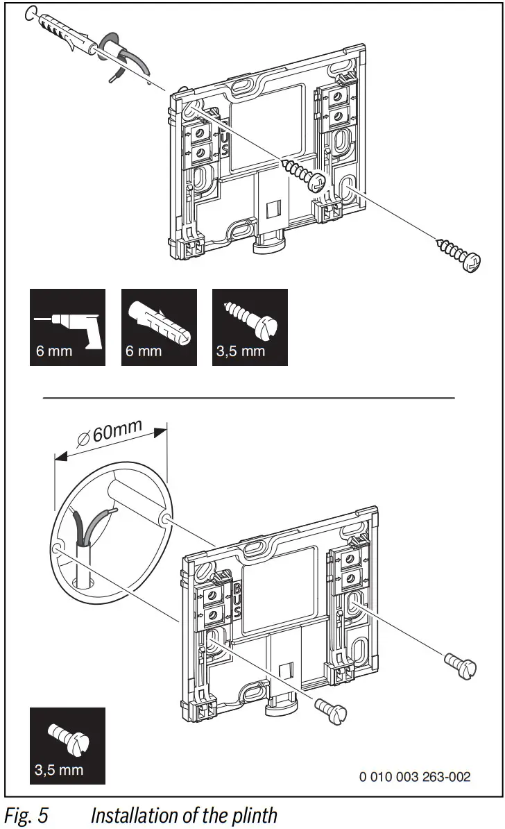
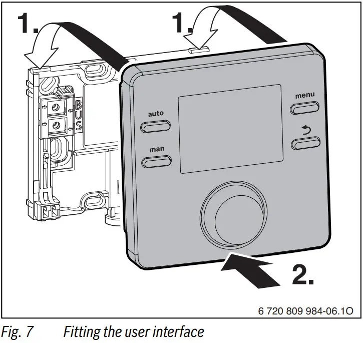
Hooking in or removing the user interface
Fitting the user interface
- Hook in the user interface at the top.
- Click in the user interface at the bottom.
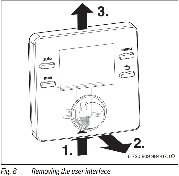
Removing the user interface
- Press the button on the underside of the plinth.
- Pull the bottom of the user interface away from the plate.
- Remove the user interface by lifting upward.
Commissioning
- First make all electrical connections and then carry out commissioning.
- Follow all installation instructions for all components and assemblies in the system.
- Turn on the mains power supply.
- Set the heat source to the maximum flow temperature needed and activate the automatic operation for water heating.
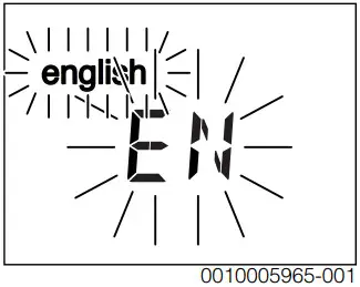
Once the user interface is connected to the power supply, the language selection appears on the display. - Make adjustments by turning and pressing the selector.
- Set the language.
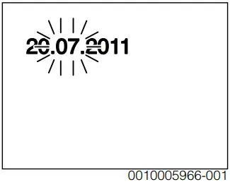
The display switches to the date setting.
- Set the date.
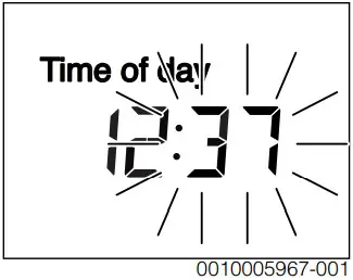
The display switches to the time setting.
- Set the time.
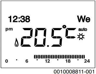
The CR 50 is now set up as a controller and the display automatically changes to the standard display. The heating system and DHW heating are operating (continuous hot water, heating according to the heating program).
The manual adaptation to the individual heating system can be performed in the service menu.
- Make the corresponding system settings, such as Control type, Max. Split., PID char act., Opt. pump run, Frost protect, Max. DHW temp
5 Shutdown / switching off
The user interface is powered via the BUS interface and is always switched on. The system should only be switched off for maintenance work, for example.
- Disconnect power from the entire system and all BUS nodes.
After a prolonged power failure or extended period of idleness, the date and time may need to be reset. All other settings are retained permanently.
- If the standard display is active, press and hold the menu key for about three seconds until the service menu appears in the main menu is displayed.
- Press the selector to open the highlighted service menu.
- Turn the selector to select a menu item or change the value of a setting.
- Press the selector to open the selected menu item, activate the input field for a setting or confirm a setting.
Depending on the control device for the heat source and BUS system employed, some menu items are displayed and cannot be adjusted using the user interface.
Service menu overview
In this menu, monitor and individually reconfigure the entire system with respect to the automatic settings.
| Menu item | Control range: Function description |
| User intern. | Controller: Use as a controller |
| HC assignment | 1 |
| Pump conn. | Heat sources: Heating pump connected to heat source |
| Heat. System | High Temp Low Temp.: Assign the heating system to the heating circuit |
| Control type | Room supply Room output: Choose the room control as either a flow temperature control or output control (output control only available with 2- wire BUS/EMS 2-BUS). |
| Config. HC1 | Hydraulic and electrical connection of heating circuit 1 to heat source (only with the EMS 2) |
| Own pump: Heating circuit pump electrically connected to the heat source | |
| P. after header: Low-loss header installed, heating circuit pump connected to heat source | |
| DHW | No: No DHW system installed |
| Yes, 3-wy valve: Existing hot water system is supplied via 3-way valve | |
| Yes, pr. pump: Existing hot water system is supplied via cylinder primary pump | |
| LLH sensor | No: No low-loss header installed |
| Yes, on appl.: Low-loss header installed, temperature sensor connected to heat source |
| Menu item | Control range: Function description |
| Recirculation | NO: The DHW circulation pump cannot be controlled by the heat source. |
| YES: The DHW circulation pump can be controlled by the heat source. | |
| Reset all | NO: The current settings have been retained. |
| YES: The factory settings are being restored (except time and date). |
Table 3 Settings in the system data menu
Settings for the heating zone are made in this menu.
NOTICE:
Risk of damaging or destroying the screed!
If an underfloor heating system is installed, observe the maximum flow temperature recommended by the manufacturer.
| Menu item | Control range: Function description |
| Max. Split. | 30 … 48 … 60 °C (example of underfloor heating system): Maximum flow temperature |
| PID char act. | Fast: Fast control characteristic, such as when there is a small heating water quantity in the air heating |
| Medium: Medium control characteristics, for example with radiator heating | |
| Slow: Slow control characteristics, for example with underfloor heating system | |
| Opt. pump run | ON: The heating pump runs as little as possible on the basis of the flow temperature |
| OFF If the system has more than one heat source installed or a buffer cylinder is installed, this function must be deactivated. | |
| Frost protect (only available with 2-wire BUS/EMS 2- BUS) | OFF: Frost protection off |
| by room temp: Frost protection is deactivated/activated on the basis of the temperature selected here | |
| DHW priority | ON: DHW heating is activated, the heating is interrupted |
| OFF: DHW heating is activated, parallel operation with heating |
Frost protection
The setting by room temp offers sufficient frost protection only if all the piping in the insulated building envelope is run in the “warm area” (no reliable frost protection if the piping is run in façades, for example).
6.3 DHW menu
Settings for water heating are made in this menu. A contractor can set a hot water temperature higher than 60 °C. Only available with EMS 2-BUS.
WARNING:
Risk of scalding from hot water!
If thermal disinfection has been set to avoid legionella (the DHW is heated once Thursday night at 02:00 to 70 °C), or the maximum storage temperature has been set to above 60 °C:
Inform all people concerned and make sure that a mixer is installed.
| Menu item | Control range: Function description |
| Max. DHW temp | 60 … 80 °C: The set value is the upper limit for the desired hot water temperature |
Table 5 Settings in the hot water menu
The system pump can be tested using this menu.
| Menu item | Control range: Function description |
| Activation | NO: All actuators return to the same position as before activating the test. |
| YES: All actuators in the system switch to the test mode. | |
| System pump | 0 (in %): Heating pump not running (switched off). |
| 100 (in %): Heating pump running at maximum speed. |
Table 6 Settings in the function test menu
Heating system settings and measurements are displayed in this menu. Changes are not possible.
| Menu item | Possible values: Description |
| Appl. oper. | ON: Burner in operation |
| Off: Burner not operating | |
| Appl.set flow | 20 … 90 °C: Flow temperature required at the heat source (set temperature) |
Troubleshooting
| Menu item | Possible values: Description |
| Appl.act.flow | 20 … 90 °C: Flow temperature measured at the heat source (actual temperature) |
| Appl.max.flow | 35 … 90 °C: Maximum flow temperature set at the heat source |
| LLT temp. | 20 … 90 °C: Current hot water temperature in the low-loss header |
| HC operation | OFF: No operation Heating: Heating mode active | Setback: Setback mode active | Manual: Manual operation active Current operating mode in heating zone. |
| HC set splay. | 20 … 90 °C: Required flow temperature in heating zone |
| Set room temp | OFF: Heating switched off, e. g. in the summer |
| 5.0… 30.0 °C: Desired room temperature | |
| Room Temp. | 5.0… 30.0 °C: Measured room temperature |
| DHW operation | ON: DHW heating active |
| OFF: Water heating not active | |
| Set DHW temp | 15 … 80 °C: Desired DHW temperature |
| Act. DHW temp | 15 … 80 °C: Measured DHW temperature |
| Max. DHW temp | 15 … 80 °C: Maximum hot water temperature set on the user interface |
Table 7 Information menu
Service-relevant settings are made in this menu, e. g. deleting the list of faults after all faults have been rectified in the course of service.
| Menu item | Control range: Function description |
| Maint.message | OFF: No service display appears on the user interface. |
| ON: A service display appears on the display of the user interface on the set date. | |
| Maint. date | 2012-01-01 – 2099-12-31: Date for next heating system maintenance. |
| Reset maint. | NO: The service display is not reset. |
| YES: The service display is reset. | |
| Current fault | such as 2012-09-29 A11/802: All current faults are displayed, arranged in order of fault severity: the date is displayed, the fault code and sub-code flash alternately in the value display. |
| Menu item | Control range: Function description |
| Fault history | such as 2012-07-31 A02/816: The last 20 faults are displayed, arranged in order of the time of occurrence. The date appears in the text line, the fault code and sub-code flash alternately. |
| Reset fault | NO: The fault history is retained. |
| YES: The fault history is deleted. |
Table 8 Settings in the Maintenance menu
Detailed information about the BUS nodes in the system can be queried in this menu. Changes are not possible.
| Menu item | Display example: Function description |
| Install.date | 2012-09-14: Date of first commissioning as a controller is automatically entered. |
| Control unit | XXXX.X: Designation of the heat source controls |
| Control SW | 1.xx.xx: Software version of the heat source controls |
| SW controller | X.xx.xx: Remote control software version |
A fault appears on the display of the user interface. The cause can be a fault on the user interface, in a component, in an assembly or on the heat source. The service manual with detailed fault descriptions contains additional information on troubleshooting.
Structure of table headers: Fault code – sub-code – [cause or fault description].
A01 – 808 – [DHW heating: hot water temperature sensor 1 faulty – replacement mode active]
| Test procedure/cause | Corrective measure |
| No hot water system installed | Deactivate hot water system in the service menu |
| Check connecting lead between controller and hot water temperature sensor | If there is a defect, replace the sensor |
| Check the electrical connection of the connecting lead in the controller | If a screw or plug is loose, rectify the contact problem |
A01 – 808 – [DHW heating: hot water temperature sensor 1 faulty – replacement mode active]
| Test procedure/cause | Corrective measure |
| Check the hot water temperature sensor according to table | If values do not match, replace the sensor |
| Check the voltage at the connecting terminals of the hot water temperature sensor in the controller according to table | If the sensor values matched, but the voltage values do not match, replace the controller |
A01 – 810 – [hot water remains cold]
| Test procedure/cause | Corrective measure |
| If the DHW priority was deselected and heating and DHW are running in parallel, the boiler’s performance may not be not sufficient | Set water heating to “priority” |
| Check the hot water temperature sensor according to table | Replace the sensor if there are deviations from the table values |
A11 – 1000 – [System configuration not confirmed]
| Test procedure/cause | Corrective measure |
| System configuration not completed | Configure system completely and confirm |
A11 – 1010 – [No communication via BUS interface EMS 2]
| A11 – 1010 – [No communication via BUS interface EMS 2] Test procedure/cause Corrective measure | |
| Check whether BUS cable was connected incorrectly | Rectify wiring faults and switch controller off and on again |
| Check whether BUS cable is defective. Turn the controller off and on again. | • Repair or replace the bus cable • Replace defective user interface |
| A11 – 1038 – [Invalid time/date] Test procedure/cause Corrective measure | |
| Date/time not yet set | Set date/time |
| Prolonged loss of power supply | Set date/time |
| A31 – 3021 – [Heating circuit flow temperature sensor faulty – standby mode active] Test procedure/cause Corrective measure | |
| Check configuration. The selected setting requires a flow temperature sensor | Change configuration |
| Check flow temperature sensor according to table | If values do not match, replace the sensor |
| A61 – 1010 – [No communication via BUS interface EMS 2] Test procedure/cause Corrective measure | |
| Check whether BUS cable was connected incorrectly | Rectify wiring faults and switch controller off and on again |
| Check whether BUS cable is defective. Turn the controller off and on again. | • Repair or replace the bus cable • Replace defective user interface |
A61 – 3091 – [Room temperature sensor faulty]
| Test procedure/cause | Corrective measure |
| User interface faulty | Restart autoconfiguration. All users must be on the BUS. Replace user interface |
Hex – … – […]
| Test procedure/cause | Corrective measure |
| For instance, service interval of heat source elapsed. | Service required; see documents for the heat source. |
Old electrical and electronic appliances
 Electrical or electronic devices that are no longer serviceable must be collected separately and sent for environmentally compatible recycling (in accordance with the European Waste Electrical and Electronic Equipment Directive).
To dispose of old electrical or electronic devices, you should use the return and collection systems put in place in the country concerned.
The menu items are displayed in the sequence below.
Service
System Data
– User interf. (as a controller)
– HC assignment (HK1)
– Pump conn. (pump connection to the heat source)
– Heat. System
– Control type
– Ext. Room Sens. (external room temperature sensor)
– Config. HC11) (Configuration of heating circuit 1)
– DHW
– LLH sensor (low loss header)
– Recirculation (DHW circulation pump)
– Reset all (restoration of default setting)
Heat. Circuit
– Max. Split. (maximum flow temperature)
– PID char act.
– Opt. pump run (optimum heating circuit pump operation)
– Frost protect2)
– DHW priority (DHW heating prioritized)
DHW
– Max. DHW temp (maximum DHW temperature)
Function test
– Activation
– System pump
Info
– Appl. oper. (burner in operation)
– Appl. set flow (required flow temperature)
– Appl.act.flow (measured flow temperature)
– Appl.max.flow (maximum flow temperature)
– LLT temp. (low loss header temperature)
– HC operation (heating circuit operation)
– HC set sly. (required flow temperature in heating zone)
- Available only when using heat sources with EMS 2.
- Only available with 2-wire BUS/EMS 2-BUS.
– Set room temp (desired room temperature)
– Room Temp. (measured room temperature)
– DHW operation (DHW heating operation)
– Set DHW temp (desired DHW temperature)
– Act. DHW temp (measured DHW temperature)
– Max. DHW temp (maximum DHW temperature)
Maintenance
– Maint.message (maintenance message)
– Main. date
– Reset main. (reset the service display)
– Current fault (active faults)
– Fault history (of the last 20 faults)
– Reset fault (reset fault history)
System info
– Install. date (date of installation)
– Control unit
– Control SW (software version of the control device)
– SW controller (programming unit software version)
![]() Middle East and Caucasian Area
Middle East and Caucasian Area
Bosch Thermotechnik Ishita vex Klima Tricare A.S.
Aydınevler Mahi. Inonu Cad. No:20
Küçükyalı Of spark A Blok
34854 Küçükyalı / Maltese – İSTANBUL
Tel: +90 216 432 08 00
Products manufactured by
Bosch Thermotechnik GmbH
Junkers Strasse 20-24
D-73249 Werner
www.bosch-thermotechnology.com


