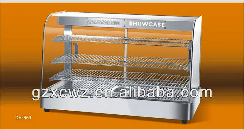
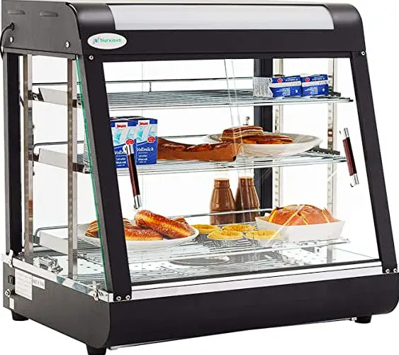
NordCap Regler ST501-LC3JAR.XXF Hot Display Case
Controller
Product description
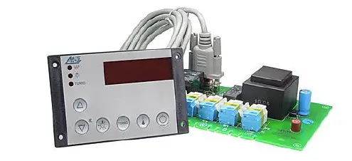
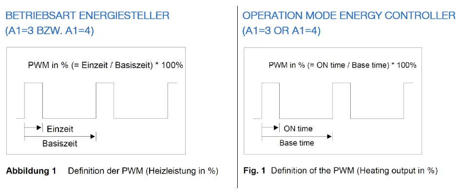
The Controller ST501-LC3JAR.XXF come with a cycling output (PWM) and works as energy regulator for infrared heaters. This controller has 2 regulated output connections, is supplied with 230V AC and offers following features:
- Providing heating power via Pulse-width modulation
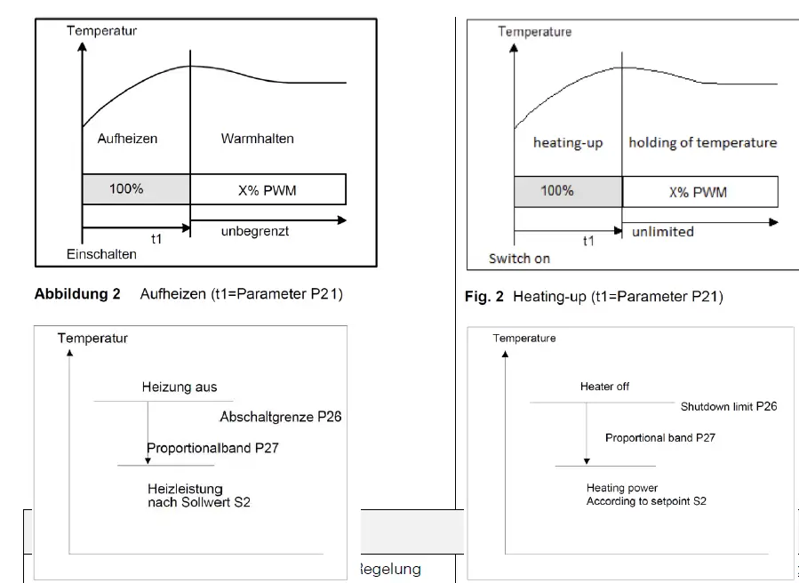
- Heat-up phase with full heating power
- Cut-off at over temperature
- Reduction of heating power at approximation to the cut-off temperature (Proportional band).
By changing the parameter „A1“ the energy regulator can be used as standard thermostat relay
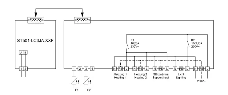
Connecting diagram
Keys
- Key UP:
Pressing this key you can increase the parameter or parameter value. - Key DOWN:
Pressing this key you can decrease the parameter or parameter value.
At alarm the buzzer function can be switched off with this key. - Key A:
Pressing this key executes the function referring to parameter A85. - Key B:
Pressing this key executes the function referring to parameter A86. - Key SET:
While this key is pressed, the setpoint is indicated. In addition, this key is used for setting parameters. - Key Standby:
Standby is used for switching the controller on or off. After power interruption, the controller function returns to its previous condition.
First control level
PARAMETER SETTING OF THE SETPOINT
The setpoint is regulated in different ways, depending on the mode defined by parameter A1:
| A1 | Function | Setpoint | Mode (nach A1) / Mode (referring A1) |
| 0 | Heating | S1 bzw./or S1‘ (A33) | T: Thermostat |
| 1 | Cooling | S1 bzw./or S1‘ (A33) | T: Thermostat |
| 2 | Alarm | S1 | T: Thermostat |
| 3 | Energy regulator | S2 | E: Energy cycling |
| 4 | Energy regulator with temperature | S2 | E:Energy cycling |
Depending on the operating mode (A1), not all shown parameters are active. The following descriptions and tables show Mode T for operation mode as thermostat (A1=0-2) and Mode E for operation mode as energy regulator (A1=3-4).
Pressing the SET key shows the value of the respective parameter. Additionally pressing the UP or DOWN key adjusts the value.
In operating mode A1=0 and A1=1 a setpoint
change-over (function “Setpoint S1′ enable ‘) can
be performed at corresponding parameter settings in A81/A82 with the switching input E1/E2 .
At closed inputs E1 or E2 the controller regulates to the modified setpoint S1′ and by pushing the SET button setpoint S1′ is shown.
S1’ can be defined as difference to setpoint S1 or as an absolute Setpoint (see parameter A33).
In operating mode A1=2 the relay is operated according to the parameter settings A30, P30, P31 and P32 in case of an alarm.
In operating mode A1=3 the relay is operated according to the setting in S2 and P20. The maximum output signal is adjusted by the setting in P29 and the display shows the value of P25.
The minimum output signal is adjusted by the setting in P28. The corresponding display is specified in P24. When Turbo mode is activated the maximum output signal is set to P29 for the time in P22. After this the setting according to S2 takes effect automatically.
In operating mode A1=4 an upper temperature limit
(P26) is set by using sensor F1. The energy level is reduced proportionally in the area (P26-P27). Power supply is stopped at temperatures higher than P26 (display 0).
| Para- meter | Mode | Description of function | Setting range | W G, W KO, W BO, W A | heating plate | SNACK- Line |
| S1 | T | Setpoint control contact 1 | P4…P5 | 0,0°C | 0,0°C | 0,0°C |
| S1‘ | T | Difference to setpoint S1; Absolute Setpoint S1’ | -99…+99,9K (A33=1) P4…P5 (A33=2) | 0,0°C/K | 0,0°C/K | 0,0°C/K |
| S2 | E | Setpoint Energy level | P24…P25 | 7 | 8 | 8 |
Second control level (P-parameters)
SETTING OF CONTROL PARAMETERS
Simultaneously pressing the UP and DOWN key for at least 4 seconds opens a parameter list containing control parameters (starting at P0).
With the UP and DOWN keys the list can be scrolled in both directions.
Pressing the SET key will give you the value of the respective parameter. Additionally pressing the UP or DOWN key adjusts the value.
After releasing all keys, the new value is saved permanently.
Return to the initial display is performed automatically, if no key is pressed for 60 seconds, or by simultaneously pressing the UP and DOWN keys for approx. 4 seconds.
The column “Mode” shows the parameters in reference to operation Mode A1.
Applies for: A1=0-2 in Mode T, A1=3-4 in Mode E
| Para- meter | Mod e | Description of function | Setting range | W Ge n closed | W KO / W BO offen open | heating plate | SNACK- Line |
| P0 | TE | Actual measuring value | – | – | – | – | – |
| P2 | T | Hysteresis contact K1 | 0,1…99,9K | 1,0 K | 1,0 K | 1,0 K | 1,0 K |
| P4 | T | minimum setpoint limitation | -99°C…P5 | 20°C | 20°C | 30°C | 20°C |
| P5 | T | maximum setpoint limitation | P4…999°C | 85°C | 75°C | 120°C | 85°C |
| P6 | TE | Actual value correction | -20,0…+20,0K | 0,0K | 0,0K | 0,0K | 0,0K |
| P19 | TE | Key-lock | no key-lock key-lock | 0 | 0 | 0 | 0 |
| P20 | E | PWM basis time | 10…900 sec | 60 sec | 60 sec | 60sec | 60sec |
| P21 | E | Heating-up time (100% heating power) | 0…90 min | 0 min | 0 min | 0min | 0min |
| P22 | E | Time limitation for Turbo | 0…90 min | 30 min | 30 min | 30min | 30min |
| P24 | E | Heat levels: lower setpoint limitation | 0…P25 | 1 | 1 | 1 | 1 |
| P25 | E | Heat levels: lupper setpoint limitation | P24…100 | 10 | 10 | 10 | 10 |
| P26 | E | heating temperature limit (switch- off) | 0…999°C | 80°C | 80°C | 80°C | 80°C |
| P27 | E | Proportional band | 1…99K | 10 K | 10 K | 10 K | 10 K |
| P28 | E | Min. Output–PWM–signal | 0…P29 | 30 % | 30 % | 30 % | 30 % |
| P29 | E | Max. Output–PWM–signal | P28…100 | 90 % | 90 % | 90 % | 90 % |
| P30 | T | Lower alarm value | -99…999°C | 0°C | 0°C | 0°C | 0°C |
| P31 | T | Upper alarm value | -99…999°C | 95°C | 95°C | 100°C | 95°C |
| P32 | T | Hysteresis alarm function | 0,1…99,9K | 1,0 K | 1,0 K | 1,0 K | 1,0 K |
| d0 | T | Defrosting interval | no defrost | 8 | 8 | 8 | 8 |
| d2 | T | Defrosting temperature limit | -99,0…999,9°C | 10,0°C | 10,0°C | 10,0°C | 10,0°C |
| d3 | T | Defrosting time limit | no time limit | 30 min | 30 min | 30min | 30min |
PARAMETER DESCRIPTION
P0: current actual value sensor F1
Here the actual value of sensor F1 is displayed. This parameter is useful to make an offset correction by parameter P6.
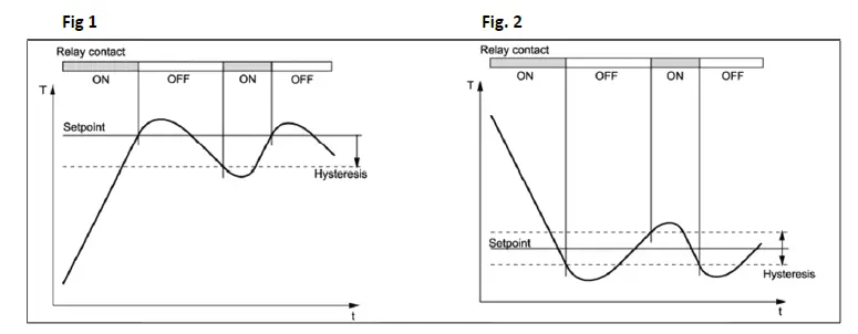
- P2: Hysteresis contact K1 (only for mode T)
The hysteresis can be set symmetrically or one-sided at the setpoint (see A40).
At one-sided setting, the hysteresis works downward with heating contact and upward with cooling contact. At symmetrical hysteresis, half of the hysteresis’ value is effective below and half of the value above the switching point (see fig. 1 and 2).
- P4: Setpoint S1: lower limitation (only for mode T) P5: Setpoint S1: upper limitation (only for mode T) The adjustment range of the setpoint can be limited in both directions.
This is to prevent the end user of a unit from setting inadmissible or dangerous setpoints. - P6: Process value correction
This parameter allows the correction of actual value deviations caused for example by sensor tolerances or extremely long sensor lines. The regulation measure value is increased or decreased by the here adjusted value. - P19: Key-lock
The key-lock allows blocking of the control keys. In locked condition parameter adjustments with keys are not possible. At the attempt to adjust the parameters despite key-lock the message “—” appears in the display. - P20: Cycle time (only for mode E)
This time ist he sum of an „ON time“ and an „OFF time“ in heating mode. (PWM base time) - P21: Heating-up time after Mains On (only for mode E) When controller is switched on, the heater is set to maximum power level for the time entered here. After expiry of the time energy level is switched to the value of Setpoint S2.
- P22: max. time for Turbo-mode (only for mode E) When the controller is switched to Turbo mode, the heater is set to maximum power level for the time entered here.
After expiry of the time energy level is switched to the energy level value of Setpoint S2. - P24: Setpoint S2: lower limitation (only for mode T) P25: Setpoint S2: upper limitation (only for mode T) The setting range of setpoint S2 can be limited downwards and upwards.
This will prevent an end customer to set forbiden or dangerous points.
The corresponding output signal is set in parameters P28 (min) and P29 (max). - P26: Switch-off temperature (only for mode E)
- P27: Switch-off temperature (only for mode E)
In operating mode A1=4, power controller with temperature limit, the energy of P26 to P27 is controlled proportionally. Above the temperature of P26, the energy supply is locked, i.e. 0. - P30: Lower alarm value (only for mode T)
- P31: Upper alarm value (only for mode T)
The output alarm is a boundary alarm or a range alarm with hysteresis (see parameter P32).
Both at the boundary alarm and the range alarm, limit values can be relative, i.e. going along with the setpoint, or absolute, i.e. independent of the setpoint.
At boundary alarm the hysteresis works one-sided inwardly, and at range alarm outwardly. - P32: Alarm hysteresis, one sided (only for mode T) Hysteresis is set one-sided at the adjusted limit value. It becomes effective depending on alarm definition.
- d0: Defrosting interval (only for mode T)
The “defrosting interval” defines the time, after which a defrosting process is started. After each defrosting start, this time is reset and runs the next interval. - d2: Defrosting temperature limit (only for mode T) This permits to terminate defrosting when the adjusted desired temperature value is reached. The defrosting time set with “d3” nevertheless runs at the same time, i.e. it functions as safety net to terminate the defrosting process in case the defrosting temperature is not reached.
- d3: Defrosting time limit (only for mode T)
After the here set time the defrosting process is terminated.
Third control level (A-parameters)
SETTING OF CONTROL PARAMETERS
Access to the third control level is granted when selecting the last P-parameter (d3) on the second control level. Continue to press the UP key for approximately 10 seconds until “PA” appears at the display.
Continue to press the UP key and additionally press the DOWN key for about 4 seconds and the first
A-parameter of the third control level is indicated.
With the keys UP and DOWN you can scroll the list in both directions.
Pressing the SET key will give you the value of the respective parameter.
Additionally pressing the UP or DOWN key adjusts the value.
By releasing all keys the new value is saved permanently.
Return to the initial position takes place, if no key is pressed for 60 seconds, or by simultaneously pressing the UP and DOWN key for approx. 4 seconds.
The column “Mode” shows the parameters in reference to operation Mode A1.
Applies for: A1=0-2 in Mode T, A1=3-4 in Mode E.
| Para- meter | Mode | Function description | Adjustment range | W G, W KO, W BO, W A | heating plate | SNACK- Line |
| A1 | TE | Switch function of control contact | 0: Heating contact 1: Cooling contact 2: Alarm function 3: Energy controller 4: Energy controller with temperature limit | 0 | 4 | 4 |
| A3 | T | Function at probe failure | 0: at failure: off 1: at failure: on | 0 | 0 | 0 |
| A8 | T | Display mode (parameter indications: 0,1K) | 0: integrals 1: decimals in 0.5K 2: decimals in 0.1K | 1 | 1 | 1 |
| A9 | TE | Weighting factor (probe) | 0,50…1,50 | 1,00 | 1,00 | 1,00 |
| A19 | TE | Parameter lock | 0: no locking 1: A-parameters locke 2: A– and P–parameters locked | 0 | 0 | 0 |
| A30 | T | Type of alarm function | 0: boundary alarm, relative 1: boundary alarm, absolute 2: range alarm, relative 3: range alarm, absolute 4: boundary alarm, relative, inverted 5: boundary alarm, absolute, inverted 6:range alarm, relative, inverted 7 range alarm, absolute, inverted | 0 | 0 | 0 |
| A31 | TE | Special function at alarm (Buzzer, Display) | 0: no special function 1: flashing display 2: buzzer 3: flashing display and buzzer 4: like 3, buzzer can be acknowledged 5: like 4, cancelled buzzer restarts after 10 min. 6: like 4, cancelled buzzer restarts after 30 min. | 0 | 0 | 0 |
| A32 | TE | Display mode | 0:actual value 1: setpoint | 0 | 0 | 0 |
| A33 | T | Type of setpoint S1‘ | 0: no function 1: relative to “Setpoint 1” 2: free adjustable | 0 | 0 | 0 |
| A40 | T | Hysteresis mode for heating and cooling mode | 0: symmetric 1: one-sided | 1 | 1 | 1 |
| A50 | T | Minimum action time controller contact „On“ | 0…600 s | 0 | 0 | 0 |
| A51 | T | Minimum action time controller contact „Off“ | 0…600 s | 0 | 0 | 0 |
| A54 | T | Delay controller contact after „Power On“ | 0…600 s | 0 | 0 | 0 |
| A56 | T | Alarm suppression after “Power-On” or setpoint modification | 0…60 min | 0 | 0 | 0 |
| A60 | TE | Sensor type | 11: Pt100-2 wire 21: PTC- 2-wire 22:Pt1000–2 wire | 21 | 11 | 21 |
| A70 | TE | Software filter | 1: not active 2..64: Average value by :meassuring values | 8 | 8 | 8 |
| A80 | TE | Temperature scale | 0: Fahrenheit (AUS) 1: Celsius (AUS) 2: Fahrenheit (OFF) 3: Celsius (OFF) | 1 | 1 | 1 |
| A81 | TE | Function E1 | 0: No function 1: Controller On/Off (Standby) 2: Activate Setpoint S1‘ | 0 | 0 | 0 |
| A82 | TE | Function E2 | 0: No function 1: Controller On/Off (Standby) 2: Activate Setpoint S1‘ | 0 | 0 | 0 |
| A85 | TE | Function key A (if present) | 0: no function 1: Display actual value (if A32=1) 2: Activate setpoint S1‘ 3: Relay direct (“Off” if Standby) 4: Relay direct 5: Turbo (Mode: E) / Turbo (Mode: E) |
4 | 0 |
4 |
| A86 | TE | Function key B (if present) | 0: no function 1: Display actual value (if A32=1) 2: Activate setpoint S1‘ 3: Relay direct (“off” if Standby) 4: Relay direct 5: Turbo (Mode: E) | 5 | 5 | 5 |
| A87 | TE | Funktion standby key | Controller On/Off (Standby) | 1 | 1 | 1 |
| L0 | TE | Own adress ST-Bus | deactivated 1 … 250 | 1 | 1 | 1 |
| Pro | TE | Program version | – | – | – | – |
PARAMETER DESCRIPTION
- A1: Operation mode
Depending on the operating mode, not all parameters are effective. In the descriptions and tables
mode T appears by specifying the thermostat operation type and mode E for the energy regulator.
The mode for the controller is adjustable as follows:A1 Function Setpoint Mode (referring A1) 0 Heating S1 bzw./or S1‘ (A33) T: Thermostat 1 Cooling S1 bzw./or S1‘ (A33) T: Thermostat 2 Alarm S1 T: Thermostat 3 Energy regulator S2 E:Energy regulator 4 Energy regulator with temperature S2 E:Energy regulator - A3: Function at sensor failure (only for mode T)
At sensor failure the controller contact is set to state of A3.
If an error in the parameter memory is detected
(display EP) and therefore the saved settings can not be used, all relays are set to deenergized state. - A8: Display mode (only for mode T)
The process value can be indicated in integrals or with decimals in 0,5°C or 0,1°C.
At indication in 0,5°C the value is rounded up or down.
In general, all parameter indications are presented at 0,1°C resolution.
In mode E the ressult always is indicated in integrals. - A19: Parameter lock
This parameter enables locking of each parameter level. If third level is locked, only parameter A19 may be changed.
This parameter enables locking of each parameter level. If third level is locked, only parameter A19 may be changed.
When attempting to adjust the parameters despite key lock, the message „—” appears on the display. - A30: Alarm mode (only for mode T)
The alarm output evaluates an upper and a lower limit value (see parameters P30 and P31), whereas a selection is possible as to whether the alarm is active if the temperature is inbetween these two limits, or whether the alarm is released if the temperature is beyond them. In the case of sensor error, the alarm is activated independently of this adjustment. - A31: Special function at alarm
Here can be selected whether, in the case of an alarm, the indication to flash and/or the buzzer is to start.
An alarm is acknowledged by pressing the DOWN key. The buzzer can be muted independently of a present alarm. - A32: Display mode
- A32=0 indicates the actual value, A32=1 statically indicates the setpoint S1 or S1’ in the display.
- A33: Mode of setpoint S1‘ (only for mode T)
The modified setpoint S1′ is either defined as difference to the setpoint S1 (relative to S1) and at change of S1 tracked at the same distance, or it is defined as the independent absolute value of S1. - A40: Hysteresis mode controller (only for mode T) This parameter allows to select whether the hysteresis value is set symmetrically or onesided at the respective switching point. At symmetrical hysteresis, half of the hysteresis’ value is effective below and half of the value above the switching point. The onesided hysteresis works downward with heating contact and upward with cooling contact.
- A50/A51: Minimum time controller contact „On“ and „Off“ (only for mode T)
These parameters permit a delay in switching on/off the relay in order to reduce the switching frequency.
The adjusted time sets the entire minimum time period for a switching-on or switching-off phase.
This time is effective even when configured as alarm contact. - A54: Delay after “Power-on” (only for mode T)
This parameter allows a switching-on delay of relays after switching-on the mains voltage.
Thus, an overload of the power supply by simultaneous switching of many consumers can be avoided. - A56: Alarm suppression after “Power-On” or change of setpoint (only for mode T)
After switching on the control a certain time passes until the operating temperature is reached, especially in cooling mode. It would cause an unwanted alarm.
This parameter allows a switching-on delay of the alarm contact after switching on the mains voltage or setpoint change-over. (S1 <-> S1′). - A60: Sensor type
Selection of sensors. In operation mode A1=3 this setting is ignored. - A70: Software filter
With several measuring values, it is possible to obtain an average value. - A80: Temperature scale
Indication can be switched between Fahrenheit and Celsius. At conversion, the parameters and
setpoints maintain their numerical value and adjustment range. (Example: A controller with the desired value of 0°C is switched to Fahrenheit. The new desired value is then interpreted as 0°F,
which corresponds to a temperature of -18°C). - A81: Function E1
- A82: Function E2
The function of the corresponding switching input is set in this parameter.
0: the switching input is not evaluated
- Via external contact E1 the control can be switched on or off (standby).
If at the same time also A81=1 AND A82=1 is set, then both functions are parallel and the last executed switch request is valid. - The external contact E1 switches from setpoint S1 to a modified setpoint S1′ (see A33)
- A85 Function key 4: Function key A A86 Function key 5: Function key B
- 0: no function
- actual value will be indicated if A32=1, otherwise no function
- Setpoint S1 is switched to setpoint S1’ (see A33)
- Relay direct (example: for light), at Standby relay is off
- Relay direct (example: for light), independent from Standby
- Turbo, only in Mode E, der controller iss et to max. energy level. The maximum time can be set in parameter P22.
The maximum energy level is given by the parameter P25 and the output signal by the parameter of P29.
Note: Is a setting other than 3 or 4 selected, K2 switches together with the controller on/off. - A87: Function standby key
The function of the Standby key (if present) is adjusted in this parameter. - L0: Adress in the ST-Bus-Net
With this parameter, the address of the device is set. Therewith the regulator can be responsed in the ST-bus network.