NordCap ST200 Cooling Zone Controller
Programming instructions circuit diagram
Product and programming description
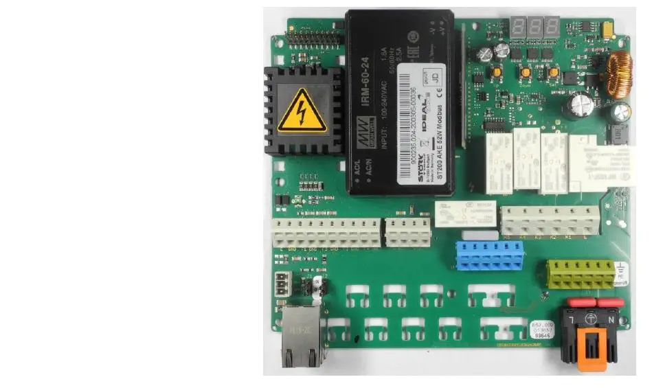
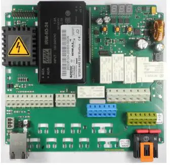
Cooling zone controller ST200
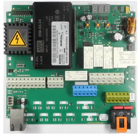
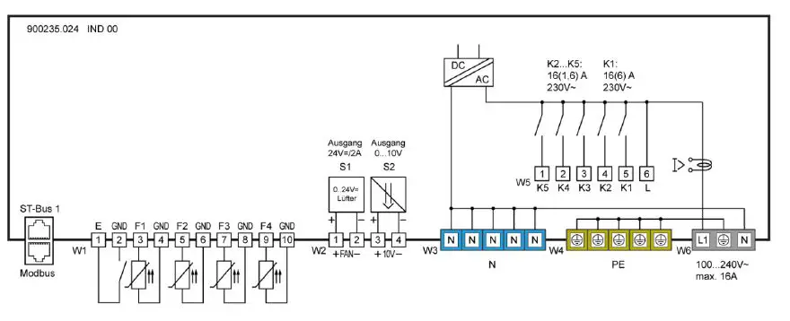
Circuit diagram
Product description
The ST200 cooling zone controller is used for thermostatic temperature control. The controller can be supplied with 100..240 V AC 50/60 Hz and has five output relays that can be freely programmed for controlling a compressor, evaporator fan, lighting or other necessary outputs. It is operated either directly on the box or via a separate, connectable display. The controller has a three-digit display and three control buttons. Parameterisation is handled in different operating levels in which access becomes increasingly difficult for security reasons. The controller is networked by means of an ST bus or Modbus interface respectively.
- Sensors: Pt100, Pt1000, PTC
- Connector: WAGO connector + spring loaded terminals
Pressing this button increases the parameter or parameter value. Pressing the button for 10 seconds triggers an unscheduled defrosting of the refrigeration system.
Pressing this button decreases the parameter or parameter value.
Pressing the SET button displays the set-point value. Pressing the button for 10 seconds switches the controller to stand by mode. The refrigeration controller is generally operated with the buttons UP and DOWN and SET. The default display shows the temperature of the cooling chamber (actual temperature value. When the SET button is pressed, the display changes to the cooling chamber temperature desired by the user (set-point temperature value. It is only possible to change the set-point temperature value by simultaneously pressing the SET and UP or alternatively SET
und DOWN buttons. While pressing the buttons, you can read the changed set-point value in the display. After changing the set-point temperature value and releasing the buttons, the actual temperature value appears in the display again. This is the standard value setting method.
SETTING THE MAIN SET POINT VALUE
Pressing the SET button will show the set-point value in the display. If the set point value needs to be changed, the SET button must remain pressed for the duration of the setting, while the UP or DOWN buttons are used to set the desired value. After selecting the setting, the UP or DOWN button must always be released first and then the SET button. You will notice that the set-point value can only be changed within the set-point value limits that have been set.
PARAMETERISATION
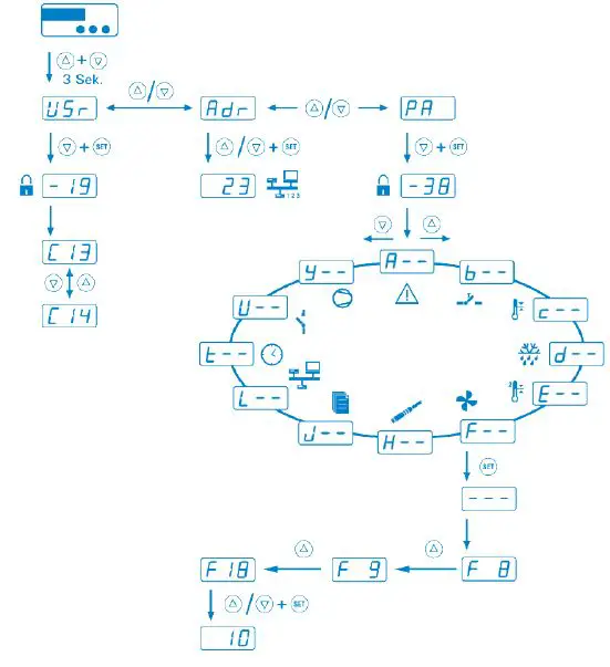
Parameterisation of the cooling zone controller is carried out at the factory or by specialists when a cooling system is put into operation. Incorrect or improper parameterisation can lead to malfunctions and thus to damage to the refrigerated product. The parameters can only be set by means of one or more passwords. Parameterisation can be carried out at any time. The regulation is not interrupted by the parameterisation, but it can directly affect it. If no button is pressed for 2 minutes, then the process is aborted and the actual value is shown again. Parameterisation can be accessed by simultaneously pressing the UP and DOWN buttons. After approximately 3 seconds, the code word appears in the display. By pressing the UP or DOWN button respectively, you can change between the code words. All other settings or default values in the parameterisation level are carried out using the general method for setting values, in other words by simultaneously pressing the SET and UP or DOWN buttons. You can use the UP and DOWN buttons to scroll within the parameter group or to change individual parameter values using the standard value setting method. By pressing the UP and DOWN buttons simultaneously, it is possible to exit a parameter group and return to the list of parameter groups. It is possible to exit from the list of parameter groups into the default level by simultaneously pressing the UP and DOWN buttons. A special case is blocking a specific parameter group with a password. In this case just as when entering the parameterisation level – you are first of all expected to input a specific password for the parameter group.
USER LEVEL
By selecting the code word US and entering the password 19 you will directly reach a list with predefined parameters.
| C13 | Lower set-point value limit | JI | Predefined parameter sets |
| C14 | Upper set-point value limit | L0 | ST-Bus 1 address (own address) |
| C21 | Sensor for actual value | U4 | Relay K4 |
| C25 | Hysteresis | U5 | Relay K5 |
| F1 | Speed of evaporator fan in normal operation | b60 | Digital input E1 |
| F5 | Speed of evaporator fan during defrosting | d0 | Type of defrosting |
| F50 | PID function mode | d1 | Defrosting interval |
| F62 | Shut-off delay, comp. fan | d2 | Defrosting time limit |
| H11 | Calibration, sensor F1 | d8 | Draining time |
| H13 | Sensor type F1 | d11 | Sensor for actual value, evaporator |
| H16 | Calibration, sensor F2 | d13 | End of defrosting |
| H18 | Sensor type F2 | d20 | Function end condition |
| H21 | Calibration, sensor F3 | d21 | Sensor for actual value – end condition |
| H23 | Sensor type F3 | 11 | Frame heater cycle behaviour |
| J12 | Display language | J13 | Units °C / °F |
ALARMS
After selecting a parameter group, it is normally sufficient to press the SET button appears in the display) and then release the button. After this, the first parameter of the parameter group appears for example in parameter group A, the parameter A0. You can use the UP and DOWN buttons to scroll within the parameter group or to change individual parameter values using the standard value setting method. By pressing the UP and DOWN buttons simultaneously, it is possible to exit a parameter group and return to the list of parameter groups. It is possible to exit from the list of parameter groups to the default level by simultaneously pressing the UP and DOWN buttons. A special case is blocking a specific parameter group with a password. In this case – just as when entering the parameterisation level – you are first of all expected to input a specific password for the parameter group.
Adr NETWORK ADDRESS
The possibility of setting a network address is found under the code wordAdr. This is mandatory when starting up networked systems.
The address of the responsible controller is found under .
Overview of the software function
Parameter levels
Alarms
 Keys and switch inputs
 Control loop 1
 Defrost Control loop 1
Fan Control loop 1
 L-Networking and display
- n- Switching cycles
- o-Special functions
- P-RPS level
- t-Operating times
- Network regulation
 L-Networking and display
 Relay contacts and lamps
Parameter
USEREBENE / USER LEVEL
| Para meter | Description of function | Einstellbereich Setting range | Wert value |
| J1 | 0 … 5 | 1 |
Networking and display
| Para meter | Funktionsbeschreibung Description of function | Setting range | Wert value |
| L0 | Own address in ST bus 1 | 1..250 | 1 |
Keys and switch inputs
| Para meter | Description of function | Setting range | value |
| b60 | Entrance E1 | Disabled | 0 |
Control circuit 1
| Parameter | Description of function | Setting range | value |
| c13 | Setpoint limitation | –199,0 °C…C14 | 2°C |
| c14 | Setpoint limitation | C13… 199,0°C | 15°C |
| c21 | Actual value sensor selection | F01 F02 F03 F04 F05 F06 VF1 VF2 VF3 VF4 | 1 |
| c25 | Hysterese ZP1 | 0,1..100,0 °C | 2,0°C |
Defrosting control circuit 1
| Para meter | Description of function | Setting range | value |
| d0 | Type of defrost circuit 1 | No defrost Compressor off Electric heating Hot gas | 1 |
| d1 | Defrost interval | No defrost after time interval Defrost interval | 3h |
| d2 | Defrost time limit | 1..99 min | 60min |
| d8 | Draining time | 0..15 min | 0min |
| d11 | Actual value evaporator circuit
| inactive F01 F02 F03 F04 F05 F06 VF1 VF2 VF3 VF4 | 2 |
| d13 | Stop at defrost temperature | -199,0°C..999,0°C | 6,0°C |
| d20 | Function condition 2 | 0 | |
| d22 | F01 F02 F03 F04 F05 F06 VF1 VF2 VF3 VF4 | 0 |
Fan control circuit 1
| Para meter | Description of function | Setting range | value |
| F1 | height 510-540 mm | 0,0..100,0 % |
55% 80% 85% |
| F5 | height 510-540 m | 0,0..100,0 % | 55% 80% 85% |
| F50 | Condenser 1 mode | Disabled
| 2 |
| F62 | Fan switch-off delay | 0..999 s | 120s |
Temperature sensors
| Para meter | Description of function | Setting range | value |
| H11 | Offset correction sensor F1 | -15,0…+15,0 K C | -2,0°C |
| H13 | Disabled PTC (KTY81-121) (°C) Pt1000 (2-Leiter) (°C) Pt100 (2-Leiter) (°C) | 2 | |
| H16 | Offset correction sensor F2 | -15,0…+15,0 K | 0,0K |
| H18 | Disabled PTC (KTY81-121) (°C) Pt1000 (2-Leiter) (°C) Pt100 (2-Leiter) (°C) | 2 | |
| H21 | Offset correction sensor F3 | -15,0…+15,0 K | 0,0K |
| H23 | Sensor selection F3 | Disabled PTC (KTY81-121) (°C) Pt1000 (2-Leiter) (°C) Pt100 (2-Leiter) (°C) | 0 |
Special functions
| Para- meter | Description of function | Setting range | value |
| 011 | Door frame heating day | 0..100,0 % | 50,0% |
Relay contacts and lamps
| Para meter | Description of function | Setting range | value |
| U4 | Function relay contact K4 |
Alarm/Warning A1L A1H A2L A2H Buzzer | 9 |
| U4 | Function relay contact K4 | Deactivated (relay OFF Relay ON no protection times | 9 |
|
| Circuit 1 (C) shut-off valve 1 [0/1] Defrosting 1 (d) or hot gas1 [0/1]
Evaporator 1 (F) evaporator 1 level 1 0/1, PWM Cooling network (Y) Condenser F condenser level 1 0/1, PWM Accessories
Alarm/Warning
| ||
| U5 | Function relay contact K4 | s
| 4 |
| Set point | U14 | 4 |
PAL LEVEL
| J12 | Display in standby mode | Disabled OFF AUS DP rechts | 1 |
| J13 | Display 1 unit | 0: °C 1: °F | 0 |
Status displays and error messages
| Message | Cause | Measure |
| Hi1 | Overtemperature alarm circuit 1 Temperature above the alarm limit | |
| Lo1 | Undertemperature alarm circuit 1 Temperature below the alarm limit | |
| Hi2 | Overtemperature alarm circuit 2 Temperature above the alarm limit | |
| Lo2 | Undertemperature alarm circuit 2 Temperature below the alarm limit | |
| F1L | Fault on sensor F1, short circuit | Check sensor F1 |
| F1H | Fault on sensor F1, break | Check sensor F1 |
| F2L | Fault on sensor F2, short circuit | Check sensor F2 |
| F2H | Fault on sensor F2, break | Check sensor F2 |
| F3L | Fault on sensor F3, short circuit | Check sensor F3 |
| F3H | Fault on sensor F3, break | Check sensor F3 |
| F4L | Fault on sensor F4, short circuit | Check sensor F4 |
| F4H | Fault on sensor F4, break | Check sensor F4 |
| F5L | Fault on sensor F5, short circuit | Check sensor F5 |
| F5H | Fault on sensor F5, break | Check sensor F5 |
| F6L | Fault on sensor F6, short circuit | Check sensor F6 |
| F6H | Fault on sensor F6, break | Check sensor F6 |
| dor | Door open too long | Close door |
| EP0 | Internal fault, control unit | Repair control unit |
| EP1 | Fault in parameter memory | Check all parameters |
| EP2 | Fault in the data memory | Repair control unit |
| Sr1 | Service interval 1 (see t30, t31 and t35 … t37) | Warning messages 1 by time |
| Sr2 | Service interval 2 (see t30, t31 and t40 … t42) | Warning messages 2 by time |
| Sr3 | Service interval 3 (see t30, t31 and t45 … t47) | Warning messages 3 by time |
| Sr4 | Service interval 4 (see t30, t31 and t50 … t52) | Warning messages 4 by time |
Errors EP0 and EP1 block the controller. The controller will only be enabled after the error has been remedied. Error EP0 and EP2 can only be remedied by repair. The errors are displayed alternately with the current measured temperature


