SUPERLIFT SSLG-2 800DC Sliding Gate Opener User Manual
Dear users,
Thank you for choosing this product. Please read this manual carefully before installation and use.
Please do not forget to include this manual if you send the product to a third party.
Safety Instruction
![]() Please make sure that the power voltage being used matches with the supply voltage of gate opener (AC110V or AC220V); kids are not allowed to touch the control devices or the remote-control uni
Please make sure that the power voltage being used matches with the supply voltage of gate opener (AC110V or AC220V); kids are not allowed to touch the control devices or the remote-control uni
The remote-control unit is single button mode or three button mode (please refer to the instructions of the remote control in accordance with the actual gate opener type). The indicator light on the remote-control unit will flicker when its button is pressed. Main engine and gate can be unlocked with a disengagement wrench and the gate can be manually operated after disengagement.
Please make sure that nobody is around the main engine or gate when the switch is operated.
Please temporarily stop using the product if the main engine needs to be repaired or regulated. The installation and maintenance of the product must be carried out by professionals.
![]() Please read this manual carefully before installing、using、maintaining or repairing it. Without following this manual, any injury or property losses caused by improper use or unauthorized modification is out of the responsibility of our company.
Please read this manual carefully before installing、using、maintaining or repairing it. Without following this manual, any injury or property losses caused by improper use or unauthorized modification is out of the responsibility of our company.
Packing List (standard)
| No. | Picture | Name | Quantity |
| 1 | 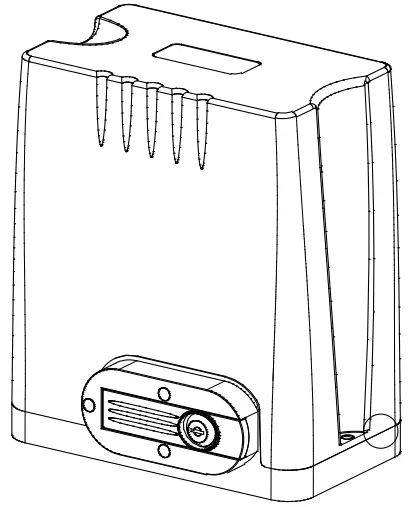 | Main engine | 1 |
| 2 |  | Manual release key | 2 |
| 3 | 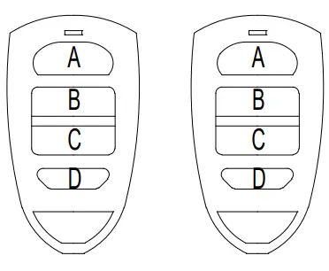 | Remote control | 2 |
| 4 | 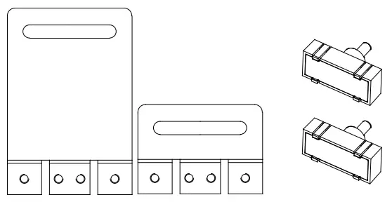 | Magnetic limit switch accessories box | 1 |
| 4-1 | 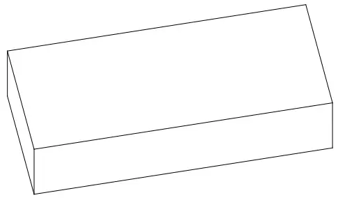 | Magnetic limit switch block | 1 |
| 4-2 | 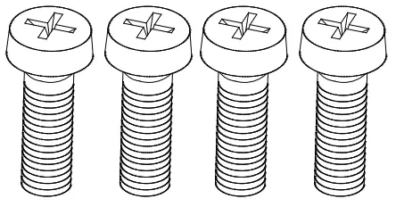 | Limit switch block mounting screw M6X18 | 4 |
| 4-3 | 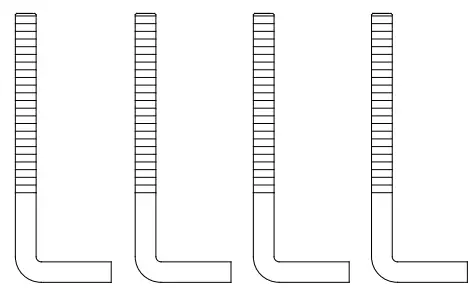 | Foundation bolt M8 | 4 |
| 4-4 | 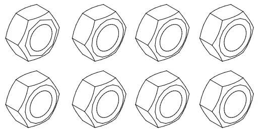 | Nut M8 | 8 |
| 4-5 | 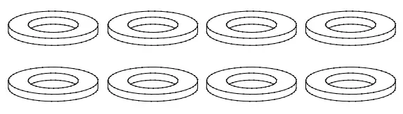 | Flat washer Ø8 | 8 |
| 4-6 | Spring washer Ø8 | 4 |
Packing List (optional)
| No. | Picture | Name | Quantity |
| 1 | 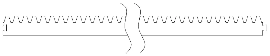 | Steel gear rack | 1m/pc |
| 2 | 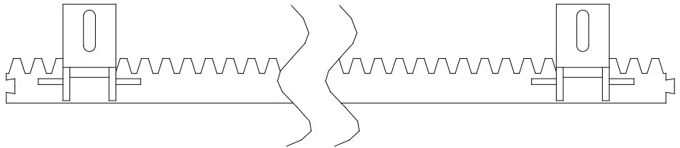 | Nylon gear rack | 1m/pc |
| 3 | 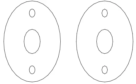 | Infrared sensor | 1 |
| 4 | 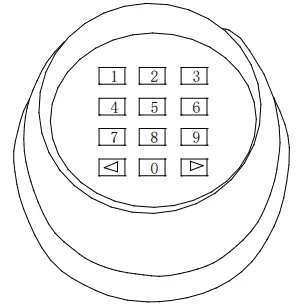 | Wireless keypad | 1 |
| 5 | 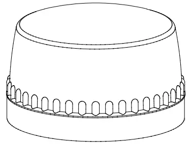 | Alarm lamp | 1 |
| 6 | 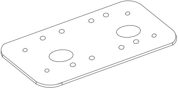 | Mounting plate | 1 |
| 7 | 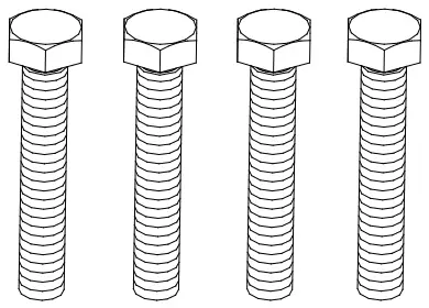 | Hexagon head bolt M8×60 | 4 |
Technical parameters
| Model | DKC500DC | DKC800DC |
| Power supply | 220V/50Hz;110V/60Hz | 220V/50Hz;110V/60Hz |
| Motor power | 150W | 170W |
| Gate moving speed | 11-13m/min | 16-18m/min |
| Maximum weight of gate | 500Kg | 800Kg |
| Remote control distance | ≥30m | ≥30m |
| Remote control mode | Single button mode / Three button mode | Single button mode / Three button mode |
| Limit switch | Magnetic limit switch | Magnetic limit switch |
| Noise | ≤58dB | ≤58dB |
| Working duty | S2, 20min | S2, 20min |
| Recording of up remote controls | 40 | 40 |
| Frequency | 433.92 MHz | 433.92 MHz |
| Working temperature | -20°C ~ +70°C | -20°C ~ +70°C |
| Package weight | 10Kg | 10Kg |
Installation
DKC500DC/DKC800DC sliding gate opener is applicable to gate weight less than 500kg/800kg, and length of the sliding gate less than 8m. The drive mode adopts the rack and gear transmission. This gate opener must be installed inside the enclosure or yard for protection.
Installation drawing
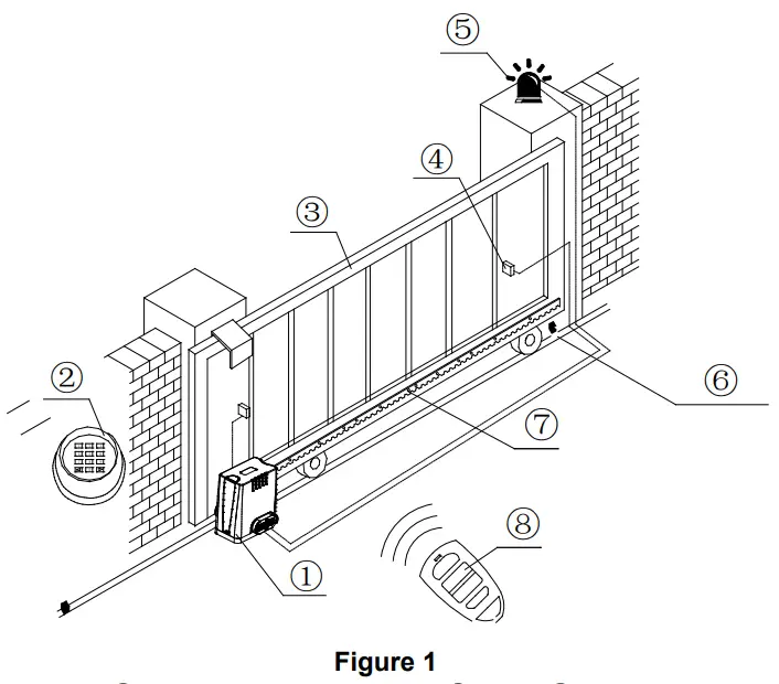
- Gate opener;
- Wireless keypad (optional);
- Gate;
- Infrared sensor (optional);
- Alarm lamp (optional);
- Safety stop block;
- Gear rack;
- Remote control;
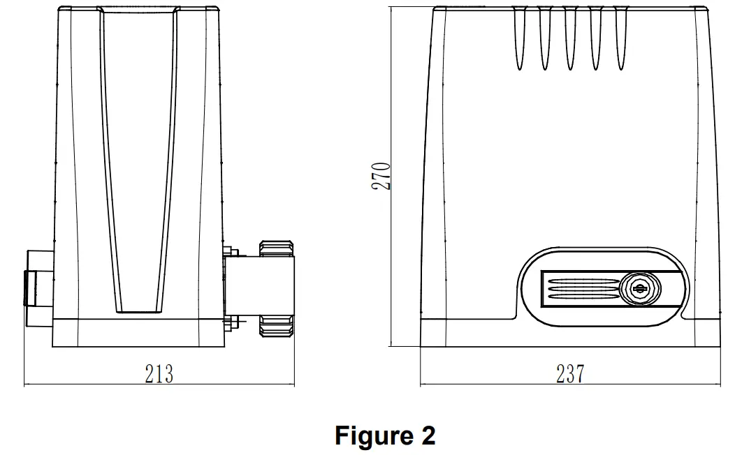
Size of main engine and accessories
Size of main engine
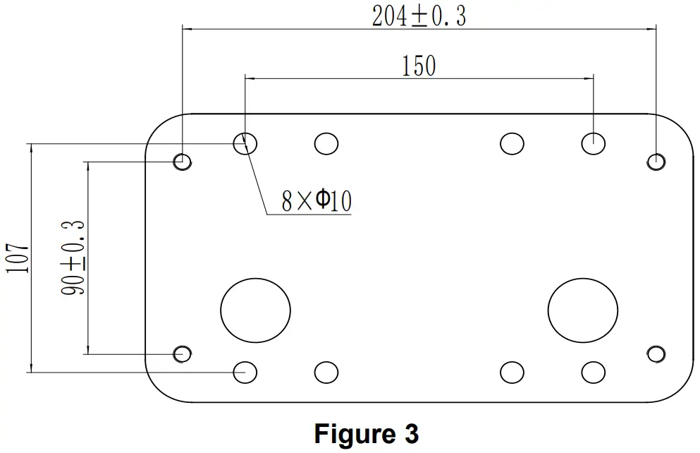
Size of mounting plate
Installation procedures
Preparation work before installation
Please make sure that the sliding gate is correctly installed, the gate rail is horizontal, and the gate can be manually moved smoothly before installing the gate opener.
Cable installation
In order to guarantee the normal operation of the gate opener and protect the cables from damages, please bury the motor & power cable and controlling cable separately with two PVC tubes.
Concrete pedestal
Please cast a concrete pedestal with the size can be 400mm x 250mm, depth be 200mm in advance, so as to firmly install DKC500DC/DKC800DC gate opener. Please make sure the distance between the gate and gate opener is appropriate before casting the pedestal.
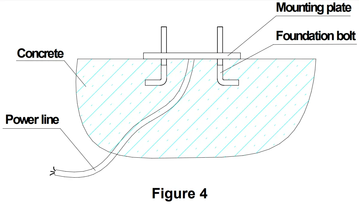
Embedded screws
Main engine installation
- Dismantle the plastic housing on the main engine before installation and keep relevant fasteners properly;
- Please prepare the power line for connecting the mounting plate to the main engine (the number of power supply cable cores should not be less than 3 PCS, the sectional area of cable core should be over 1.5mm² and the length should be determined by users according to the situation on installation spot)
- Please unlock the main engine before installation, the unlock method is: remove the rubber key cover, insert the key, and open the manual release bar till it rotates by 90° as shown in Figure 5.

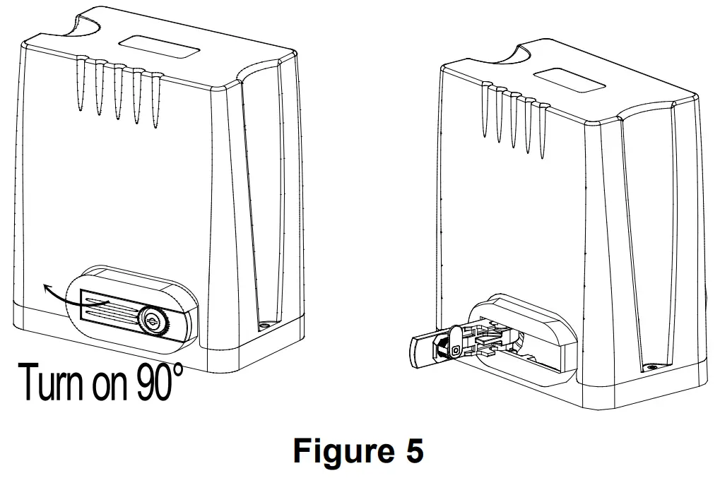
Then turn the output gear and the gear can be rotated easily;
Gear rack installation
- Fix the mounting screws to the rack.
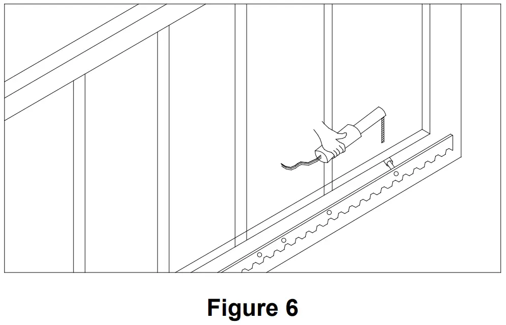
- Put the rack on the output gear, make the rack engage with the output gear then weld the mounting screw to the gate (each screw with one solder joints firstly).
- Manually move the gate (gate should be moved smoothly after motor unlocked) to check whether there is a fit clearance between rack and output gear, as shown in Figure 7.
- Weld all the mounting screws to the gate firmly.
- Make sure that all racks on the same straight line.
- Pull the gate after installed, make sure the entire trip is flexible without any stuck.

The fit clearance of output gear and rack is shown in Figure 7 below: 1-2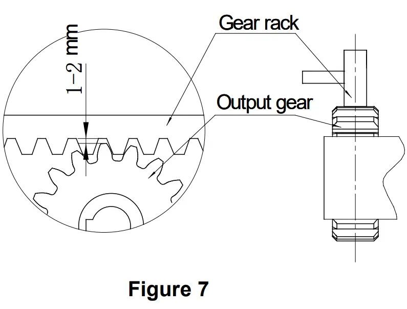
![]() Warnings
Warnings
- To ensure safety, install safety stop blocks on both ends of the rails to prevent the gate from running out of the rail. Before installing the main engine, make sure that the safety stop blocks are in place and whether it has the function of preventing the gate from running out of the rail or safety range.
- Please make sure that the main engine and its components have good mechanical properties, and the gate can be operated flexibly when manually moved before installing the main engine.
- Please note that for this product, one control can only drive one main engine, otherwise, the control system will be damaged.
- Earth leakage circuit breaker must be installed in where the gate movement can be seen, and the minimum mounting height is 1.5m to avoid being touched by children.
- After installation, please check whether the mechanical property is good or not, whether gate movement after manual unlocking is flexible or not, whether the installation for infrared sensor (optional) is correct and effective.
Limit switch adjustment
Magnetic limit switch – The installation position of magnetic limit switch is shown in Figure 8: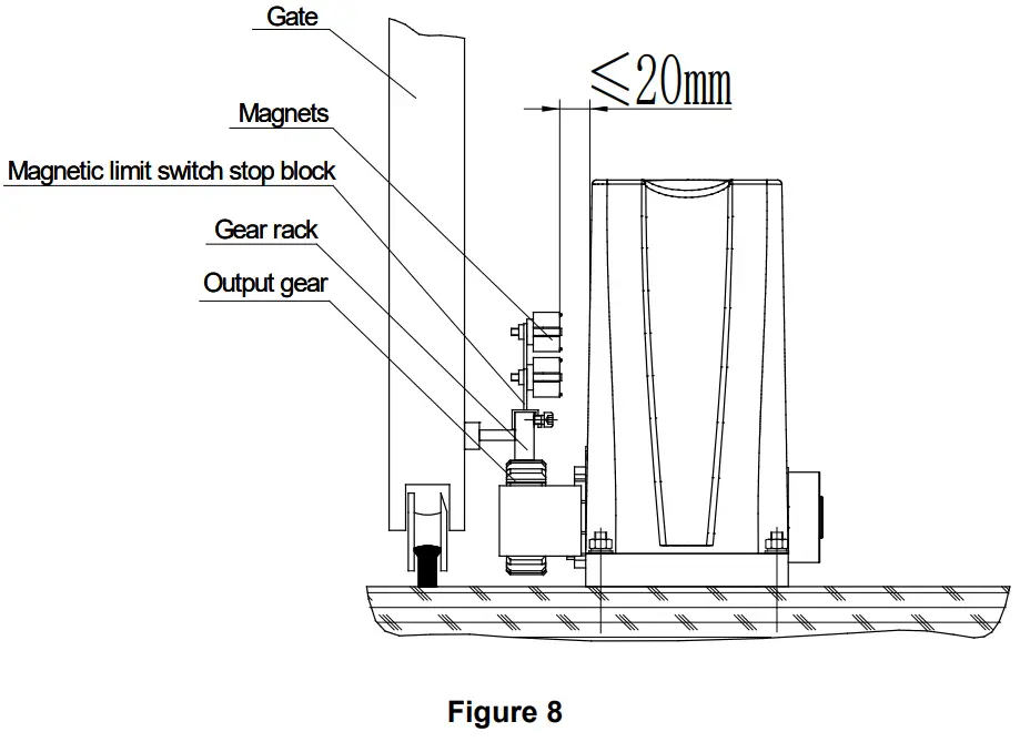
The installation of magnetic limit switch stop block is shown in Figure 9: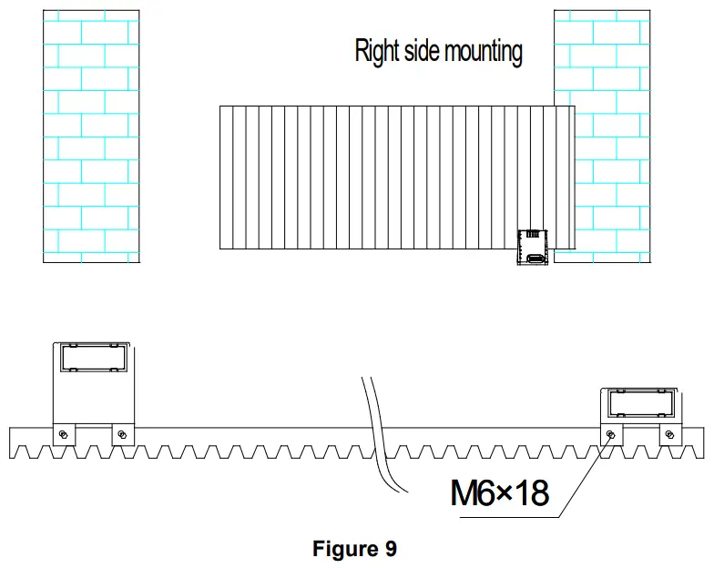
Note: The default setting is right side mounting. (According to actual situation to adjust, please refer to the section 4.3.5 “DIP switch adjustment”, to change the door opening direction through the DIP switch 5)
Note: After first installed or Re-power up, please drive one opening and closing cycle by pressing remote control button or external button, then the door width will be remembered by control unit and the “soft start slow stop” function will be enabled in next working cycle.
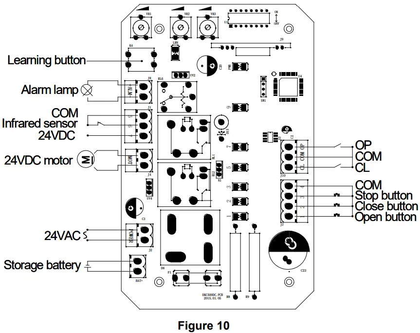
Control board wiring
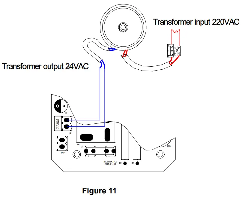
Transformer Power Input Connection
Wiring instruction:
J1 Terminal
- 5 COM (GND)
- 6 Photocell input (N.C.);
- 7 Extra power input +24VDC
J2 Terminal
Connect to 24VAC(Fig.11 shows 120W 230VAC/24VAC annular transformer connection)
BAT+ Terminal
Battery interface
J4 Terminal
DC motor wire connection (Red wire to top, black wire to bottom)
J7 Terminal
- Gate open control button (N.O.);
- Gate close control button (N.O.);
- Stop control button (N.O.);
- Control button common terminal;
J8 Terminal
24V DC caution light
J10 Terminal
OP Open limit switch;
COM Limit switch common terminal;
CL Close limit switch;
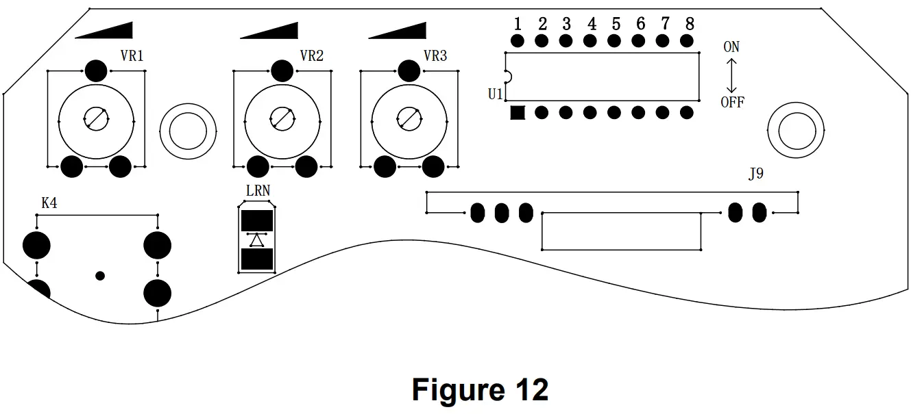
Adjusting knob
VR1: For motor working total time adjustment.
Clockwise rotation to increase, counter-clockwise rotation to reduce. The total time can be set to 10 seconds as minimum and 90 seconds as maximum. For example, if gate moves 20 seconds, please try to add 5 seconds, namely setting 25 seconds is suitable.
VR3: For motor auto-reverse force adjustment when meeting obstacle.
Clockwise rotation to increase the reverse force, counter-clockwise rotation to reduce.
DIP switch adjustment
| serial number | |
| 1 | 1 ON 2 OFF: automatic close delay time is 3s. 1 OFF 2 ON: automatic close delay time is 10s. 1 ON 2 ON: automatic close delay time is 30s. 1 OFF 2 OFF: cancel automatic close function. |
| 2 | |
| 3 | ON – Remote control is three button mode, the first button is OPEN, the second button is CLOSE, the third button is STOP. |
| OFF- Remote control is single button mode, one same button on the remote control to circularly control OPEN/STOP/CLOSE/STOP. | |
| 4 | OFF – External button switch is single button mode, connect to 1 and 4 of J7. |
| ON – External button switch is three button mode. | |
| 5 | Left and Right installation setting. OFF – Right side mounting ON – Left side mounting The change of door close direction will be valid only after the re-power. |
| 6 | Limit switch setting. ON – Normal open (N.O.); OFF – Normal close (N.C.). |
| 7 | Meet obstacle reversal function. ON – enabled; OFF – disabled. |
| 8 | Infrared detection delay when closing ON – infrared detection delay is 1 second; OFF – infrared detection delay function is disabled. |
Infrared connection
Infrared photocell function: In the closing process, when infrared ray of the photocell is covered by people or objects during its detection range, the gate will open immediately for security protection.
The distance between photocell receiver and photocell emitter should be more than 2 meters, otherwise will affect the induction of the photocell.
If connect the infrared sensor, please remove the short connection between 5 and 6 on the J1 terminal.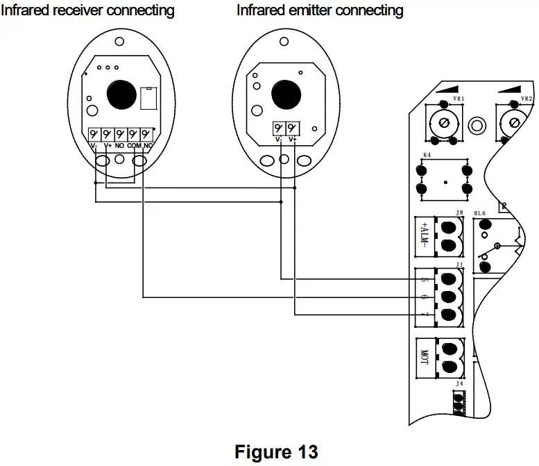
Remote control operation
Three button mode remote control: OPEN/CLOSE/STOP of main engine are controlled by three buttons separately on the remote control.
Single button mode remote control: OPEN/CLOSE/STOP of main engine are controlled by one button circularly on the remote control.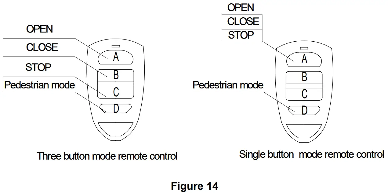
Add extra remote control (remote control learning): Remove the main engine housing, then take out the upper cover of the control box, press and hold the learning button K4 on the control board for 2 seconds, the indicator light LRN will be on; press the button that to be learned on the remote control twice, the LRN will flash several times and be off; remote control learning complete. A maximum of 40 remote controls can be learned.
Delete remote control: To delete remote control that have been learned; press and hold the learning button K4, the indicator light LRN will be on; then release it until LRN is off. After the steps, all the matched remote controls will be deleted.
The fourth button on the remote control is for pedestrian mode, press the button while the door is closed, it will open for 1 meter which is for pedestrian only
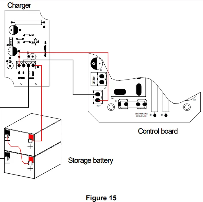
Battery connection
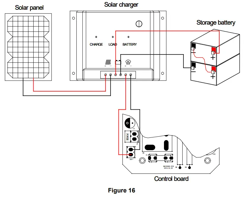
Solar panel connection
Others
Maintenance
Check whether the gate operates normally every month.
For the sake of safety, each gate is suggested to be equipped with infrared protector, and regular inspection is required.
Before installation and operation of the gate opener, please read all instructions carefully.
Our company reserves the right to change the instruction without prior notice.
Troubleshooting
| Problems | Possible Reasons | Solutions |
| The gate cannot open or close normally, and LED does not light.
|
|
|
| The gate can open but cannot close. |
|
|
| Remote control doesn’t work. |
|
|
| Press OPEN, CLOSE button, the gate is not moving, motor has noise. |
|
|
| Not stop at the limit position when opening / closing. |
|
|
| Leakage switch tripped. | Power supply line short circuit or motor line short circuit. | Check wiring. |
| Remote control working distance is too short. | Signal is blocked. | Connect external receiver antenna, 1.5 meters above ground. |
| The gate moves to the middle position to stop or reverse. |
|
|
| Gate opens automatically | Automatic close function has been turned on but with incorrect opening direction. | Please refer to the attentions under 4.3.5 “DIP switch adjustment”, to change the opening direction through DIP switch 5. |
Warranty
Warranty Ordinance
- To repair against this warranty card and invoice during the warranty period.
- Warranty period: 1 year after the date of invoice.
- Without unauthorized dismantling, any product broken or damage due to quality problem, we’ll offer the repair service for free or replace for free.
- The malfunction and damaged caused by incorrect use or man fault is not covered by this warranty.
Maintenance Record
| Check Date | Check Content | Maintained by |


 Sliding Gate Opener User Manual")
 Sliding Gate Opener User Manual")
 Sliding Gate Opener User Manual")


 Sliding Gate Opener User Manual")

 Sliding Gate Opener User Manual")


