GfA ELEKTROMATEN 10004000 10012 Sectional Door Drive
Symbols
![]() Warning – Potential injury or danger to life!
Warning – Potential injury or danger to life!![]() Warning – Danger to life from electric current!
Warning – Danger to life from electric current!![]() Note – Important information!
Note – Important information!
▶ Requirement – Required action!
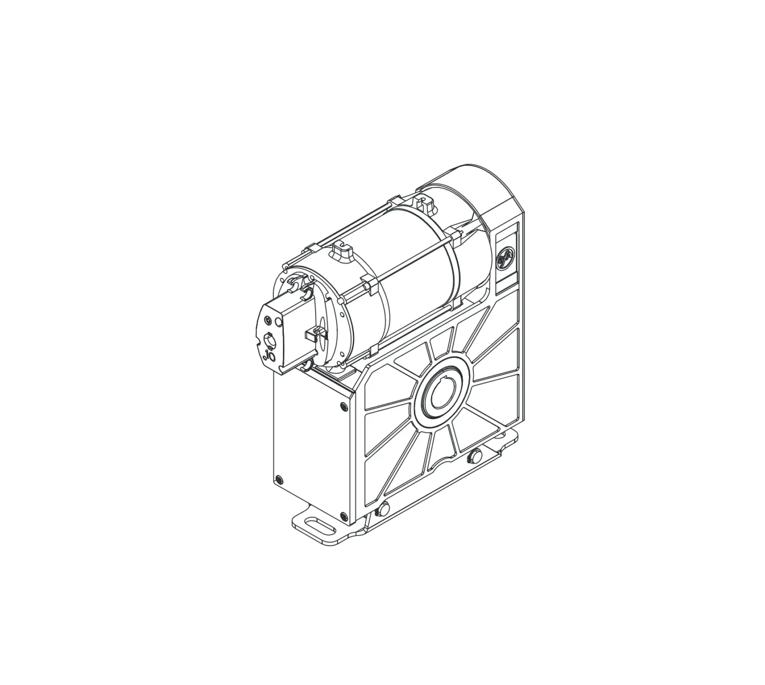
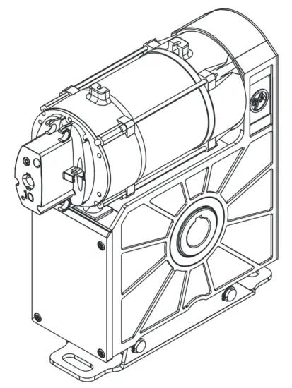
Schematic representations are based on product examples. Deviations from delivered products are possible.
General safety information
Specified use
The drive unit is intended for vertically moving doors that need to be secured against dropping. A safety brake is integrated into the gearbox. The drive unit must be mounted directly on the shaft of the door. The drive unit must be protected against moisture and aggressive environmental conditions (such as corrosive substances). The drive units are only suitable for indoor use. Appropriate protective measures must be taken for outdoor installation. The drive unit is not intended for hazardous areas. The values specified in the technical data of the drive unit must not be exceeded. The safe operation can only be ensured if used as specified.
Target audience of these installation instructions
These installation instructions are geared towards qualified persons trained in the handling of door systems. Expert knowledge, relevant skills and practical experience are what set apart qualified persons. They are capable of safely carrying out the tasks involving installation, maintenance and modernisation according to the instructions.
Safe operation
The safe operation of the product can only be ensured if it is used as specified. Follow the installation instructions. Observe all specifications, especially warnings, when installing the product in the overall system. GfA is not liable for damage resulting from non-observance of the installation instructions. The resulting overall system must be reassessed for its safety in accordance with applicable standards and directives (e.g. CE marking). These installation instructions refer only to a part of the overall system and are not sufficient as the sole instructions for the overall system. The installer of the system must prepare the instructions for the overall system. We recommend entering the danger area of the system only when the drive unit is at a standstill.
|
|
Work carried out improperly may result in death or severe injury from electrical current or falling parts.
|
Inadmissible forces (examples: collision with a forklift, dropping the drive unit, tearing or pulling on the motor) lead to damage to the drive unit. There is a risk of severe injury or death from falling objects.
|
Technical data
| Designation | Unit | |
| Output speed | 10 | rpm |
| Output torque | 250 (160) 1) | Nm |
| Output / hollow shaft | 30,00 | mm |
| Series | SG 63FK | – |
| Limit switch range (maximum revolutions of the output / hollow shaft) | 10 | – |
| Supply voltage | 1N~ 230 | V |
| Operating current | 4,50 | A |
| Operating frequency | 50 | Hz |
| Power factor cos φ | 0,99 | – |
| Safety circuit | 24 | V |
| Degree of protection | IP 54 | – |
| Temperature range | -10 / +40 (+60) 2) | °C |
| Operating sound pressure level | < 70 | dB(A) |
| Cycles per hour | 8 (2,2)1) | h-1 |
| Max. holding torque | 250 | Nm |
| Operating capacitor | 35 | µF |
| Locking torque | 510 | Nm |
| Safety brake (testing centre / approval number) | 14-003612-PR02 | – |
| Manual force emergency manual operation | 198 | N |
1) Specification in ( ) according to EN 60335-2-103.
2) When using a temperature range of +40°…+60°C use half of maximum cycles per hour.
Integrated safety brake
A safety brake is integrated into the gearbox of this ELEKTROMATEN. The safety brake protects against the door dropping due to breakage or wear of the gear teeth. The safety brake works regardless of the mounting position, speed and rotating direction. It is maintenance-free. The specification of the locking torque and the approval number of the safety brake are available in the technical data of these instructions.
If you need to apply more than the permissible force of 390N (according to DIN EN 12604/DIN EN 12453) to move the door by emergency manual operation, this indicates a stalling on the drive unit or door. Releasing the stalling may cause the door to drop.
|
Mechanical installation
Prerequisites
The permissible loads on walls, fastenings, mountings and transmission elements must not be exceeded, even for maximum holding torques or locking torques ( refer to technical data).
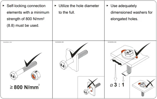
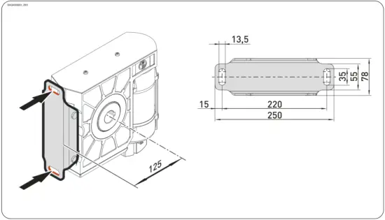
Connection elements
Permissible mounting positions
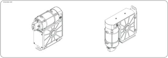
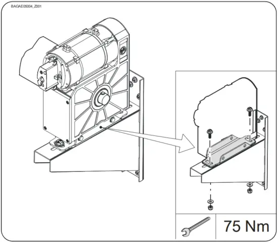
Mounting
Two elongated holes are provided for mounting.
Installation
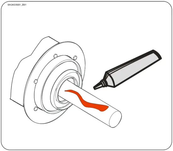
The descriptions below apply to general door specifications. The specifications of the door manufacturer must also be observed during installation.
|
- Thoroughly grease the door shaft.

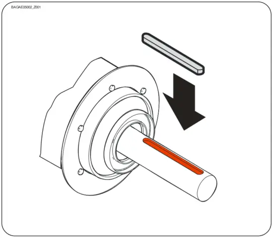
- Mount the keys.
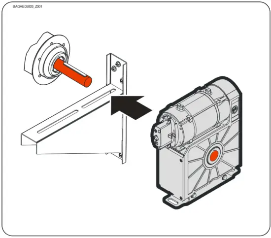
- Attach the drive unit.

- Tighten all connection elements (M12) to 75 Nm. Install all other connection elements according to the specifications of the door manufacturer.
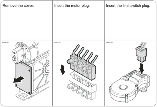
Electrical installation
|
Performing electrical installation
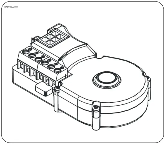
Completing the electrical installation
Mount the cable entries and/or cable glands.
Limit switch setting
The setting of the final limit positions OPEN and CLOSE is described in the instructions for the door control.
Use only door controls that evaluate the limit switch according to EN 12543 and meet Performance Level c. |
Motor connection
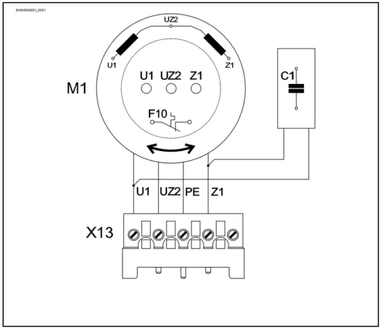
| C1 | Operating capacitor |
| M1 | Motor |
| X13 | Motor plug |
Limit switch connection
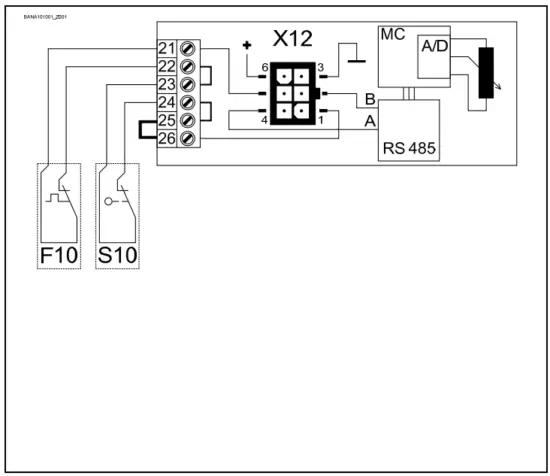
| F10 | Thermal contact |
| S10 | Emergency manual operation |
| X12 | DES connection |
| 1 | Safety circuit |
| 2 | Channel B (RS485) |
| 3 | Ground |
| 4 | Channel A (RS485) |
| 5 | Safety circuit |
| 6 | Supply voltage |
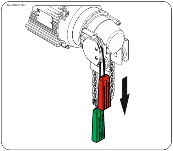
Emergency manual operation (rapid hand chain operator)
Emergency manual operation is designed for opening or closing the door without power supply. Its activation interrupts the control voltage. Electrical operation is no longer possible.
|
If you need to apply more than the permissible force of 390N (according to DIN EN 12604/DIN EN 12453) to move the door by emergency manual operation, this indicates a stalling on the drive unit or door. Releasing the stalling may cause the door to drop.
|
|
Switch on by pulling the red handle. Open or close by pulling the chain. Switch off by pulling the green handle.
Completion of commissioning / testing
Check the following components and after that, mount all covers.
Gearbox
Check drive unit for oil loss (a few drops are not critical). Protect output shaft permanently against corrosion.
Safety brake in the gearbox
The safety brake requires no maintenance or inspection.
In the case of a gearbox damage, the internal safety brake is triggered to prevent the door from dropping. The gearbox stalls. Releasing the stalling may cause the door to drop!
|
Mounting
Check all mounting elements (consoles, torque brackets, screws, retaining rings etc.) for tightness and impeccable condition.
Electric wiring
Check connection cables and cables for damage or pinches. Check screw and plug connections for correct seating and electrical contact.
Emergency manual operation
Function to be checked in a de-energised state. Carry out functional test only between final limit positions.
Limit switches
Check the final limit positions by opening and closing the door completely. The safety zone must not be reached.
Entire drive unit
Note!
|
Disposal
Dispose of packaging
Dispose of the packaging material properly according to the local legal regulations or recycle it.
Dispose of old devices
Dispose of old devices properly according to local legal regulations. Return old devices to the return and collection systems available. You can also return GfA products free of charge. Please apply enough postage to the package and mark it as “old devices”.
The gearbox contains oil.
|
Declaration of incorporation
within the meaning of Machinery Directive 2006/42/EC for partly completed machinery, Appendix II Part B
Declaration of conformity
within the meaning of EMC Directive 2014/30/EU
within the meaning of RoHS Directive 2011/65/EU
We,
GfA ELEKTROMATEN GmbH & Co. KG
declare under our sole responsibility that the following product complies with the above directives and is only intended for installation in a door system.
Drive unit
SIK 25.10 WS-30,00
Part no.: 10004000 10012
We undertake to transmit in response to a reasoned request by the appropriate regulatory authorities the special documents on the partly completed machinery.
This product must only be put into operation when it has been determined that the complete machine/system in which it has been installed complies with the provisions of the abovementioned directives.
Authorised representative to compile the technical documents is the undersigned.
Düsseldorf, 10.08.2018
Stephan Kleine
CEO
Signature
The following requirements from Appendix I of the Machinery Directive 2006/42/EC are met:
1.1.2, 1.1.3, 1.1.5, 1.2.2, 1.2.3, 1.2.6, 1.3.2, 1.3.3, 1.3.9, 1.5.1, 1.5.2, 1.5.4, 1.5.6, 1.5.7, 1.5.8, 1.5.9, 1.5.10, 1.5.11, 1.5.13, 1.6.1, 1.6.2, 1.6.4, 1.7.2, 1.7.3, 1.7.4.3.
Standards applied:
EN 12453:2001
Industrial, commercial and garage doors and gates – Safety in use of power operated doors – Requirements
EN 12604:2017
Industrial, commercial and garage doors and gates – Mechanical aspects – Requirements
EN 60335-1:2012
Household and similar electrical appliances – Safety – Part 1: General requirements
EN 61000-6-2:2005
Electromagnetic compatibility (EMC) Part 6-2 Generic standards – Immunity standard for industrial environments
EN 61000-6-3:2007
Electromagnetic compatibility (EMC) Part 6-3 Generic standards – Emission standard for residential, commercial and light-industrial environments