 mxion RBM 10A 4 Channel Track Occupancy Detector
Introduction
Dear customer, we strongly recommend that you read these manuals and the warning notes thoroughly before installing and operating your device. The device is not a toy (15+).
NOTE: Make sure that the outputs are set to the appropriate value before hooking up any other device. We can’t be responsible For any damage if this is disregarded.
General information
We recommend studying this manual thoroughly before installing and operating your new device. Place the decoder in a protected location. The unit must not be exposed to moisture.
NOTE: Some functions are only available with the latest firmware. Please make sure that your device is programmed with the latest firmware.
Summary of Functions
- Train detection module for PC controlling Control commands without PC 8A power each output, 10A peak current
- train detection inputs for 4 track sections 4 current detection for train detection
- contact inputs for switch operations Connection for a second BM over inputs
BM module is integrated
Current detection is configurable for each ch. Feedback for LocoNet + S88 + XpressNet incl. Isolated inputs for all systems Feedback via WLAN for MZSpro/30Z XpressNet feedback only for MZSpro/30Z DC/AC/DCC operation all kind of voltage Switch commands XpressNet all commands Analog and digital operation with all systems LEDs integrated (8x) for direct visualization Automatic processes can be made Wireless also by LocoNet command stations CV programming (CV, Register, Bitwise, POM) POM programming (Loco and switch) Radio feedback is possible with the module Radio feedback is easily expandable Screw drives for stable mounting
Scope of supply
Manual mXion RBM
Hook-Up
Install your device in compliance with the connecting diagrams in this manual. The device is protected against shorts and excessive loads. However, in case of a connection error e.g. a short this safety feature can’t work and the device will be destroyed subsequently. Make sure that there is no short circuit caused by the mounting screws or metal.
Connectors 

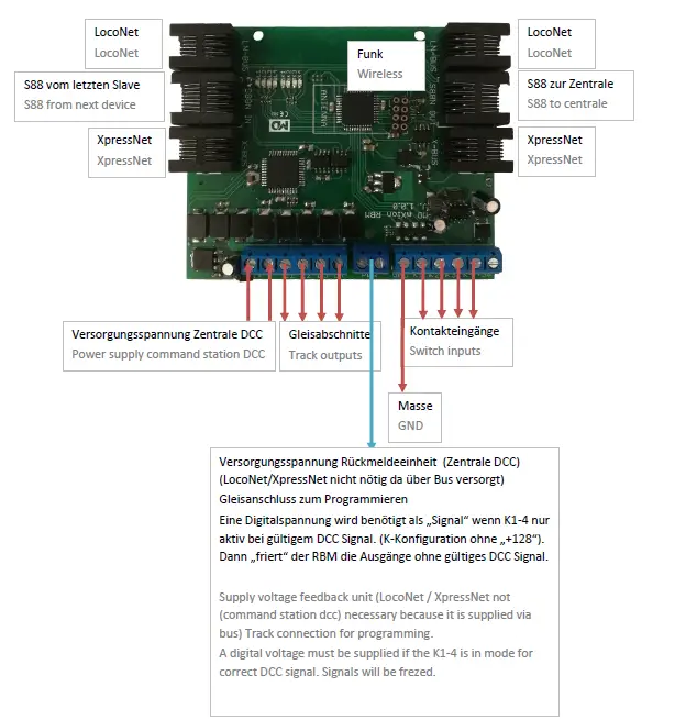
K1-K4 are 4 independent inputs. This makes it possible to confirm external switches to be able to or even complex switching tasks to be able to work off. According to the CV list, the respective K must be input can be converted and if necessary, a special function can be set. Some special functions work with 2 contact inputs (e.g. direction-dependent turn). This requires 2 contact outputs which are configured as input and together take over a shift task. Likewise, the contacts can also be directed against the digital track can be switched (sensor track) to detect a train and a switch or to have a signal switched. So are semi-automatic processes possible without any PC? Switching tasks (e.g. contact switches turnout or directional contact release switches switch is possible with any XpressNet-enabled center but feedback and ratio only work on ours central stations over Xpressnet! 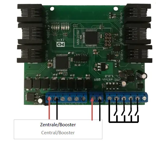
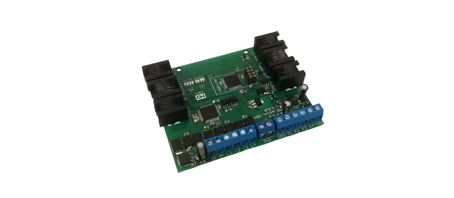
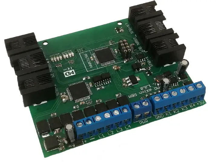
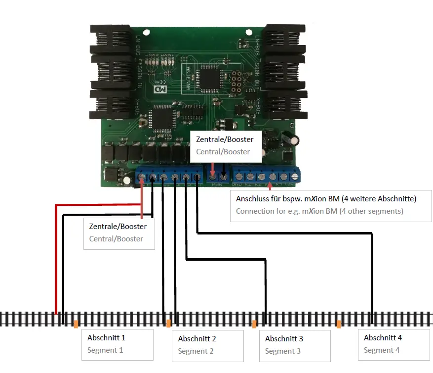
Product Description
The mXion RBM is a universal, analog, and digital (any format/system) usable occupancy detector for the detection of electricity consumers within a section. The module supports 4 sections and can these ads or as switch contact feedback. Is loaded consumer within a segment, switches the contact number and is displayed on the RBM itself with the integrated LEDs. For the free 4 contacts, another BM module from us can be used for this connection so that in total 8 sections can be monitored. The configuration is done via CV programming. Ideal for displaying track plans with a display of currently occupied track sections, PC control, and much more. For feedback to the center is a corresponding feedback module not requ. For S88 and XpressNet there is also a feedback build in which the feedback is easily possible. The module can by CV-Programming with div. modes are set. Underneath it is also possible to configure the signaling outputs (K1-K4) as input (for external occupancy detectors as BM or switch contacts). In addition, automated processes can also be used be configured like switching turnouts, also depending on the direction depending on the configuration. The current detection limit can be set via CV in very small sets. The double flash of the middle two LEDs will show the correct working wireless module.
Switch and contact inputs
The contact and switching inputs K1-4 are protected entrances so here too just a circuit to ground (or that digital track) is recognized. Isolation does not have to be respected. Also, sensor tracks are permitted as a contact. K1-4 can with some modes are operated for automatic processes.
Wireless connection
The RBM can with our radio module be equipped and wireless to report back to headquarters. Then he only needs an external power supply (e.g. track). The feedback will also work on LocoNet command stations, where the first RBM is working as a master. The wireless module will be correct if the middle 2 LEDs are flashing by start.
Level controlling
Each close contact in mode switch control level dependent for K1-K4 switches the associated one in the address CV entered turnout address to right each open to the
left. The direction is invertible via CV. So that can be set up as simple control panels.
Direction depending contacts
When using 2 track contacts in a row arranged the direction of travel can be reported. As an example: first trigger K1, then K2 reports K1. If K2 then K1 triggered, reports K2.
Train detection mode
Upon delivery, all contact inputs are open occupancy reports made (mode 6). This mode is meant for trains and their position on recognizing the system and using a PC control. To contacts, K1-4 can switch. sensor or better to connect our BM module. A BM is already integrated in the RBM and manages L1-L4. Only mode 6 is fixed here set possible as feedback.
Settings and programming
The module settings are made via DCC by means of a programming track or via POM. Important it ist that no bus cable is plugged in otherwise programming is not possible.
For the elderly control, units can be programmed using registers 7 and 8. It is recommended blocking of the module after successful programming using CV6 = 0.
Bus system S88
The RBM controls the S88 bus system. This pure one feedback bus can be used at many common command stations, can also be used with our 30Z. Here, all 4 contact inputs and 4 BM inputs (total 8 contacts) reported back whether this is closed or open. It is not an address or programming necessary. The modules are connected in series. Only CV35 is important. Here the pulse train for the first module set directly at the control center. With some command stations (e.g.DR5000) this is necessary if the address of the first contact shifts, the offset is given here. With the DR5000 is 16. At our headquarters, a 0 must be entered here.
Bus system LocoNet
The RBM masters the LocoNet. The block all commands of contacts K1-4 accordingly run after configuration and thus is too possible with the RBM automated switches to be able to switch. For pure feedback (mode 6) there is no need to change the CV will. The modules are just going on connected the bus. The addressing happens automatically. Only the contact address (or the switch address) to be switched depending on the mode must be configured.
Bus system XpressNet
When using the XpressNet bus is one program unique address (CV1). Each block must have a unique address own that centers can use the XpressNet bus only the modes of the K1-4 of 1,3 and mode 5 are used. All other modes of contact inputs are only possible at our headquarters! As well the feedback is ONLY possible at our command stations. Please refer to the instructions of the respective command station.
Calculation contact addresses
The contact addresses are K1-K4 and L1-4 equivalent to calculating turnout addresses (see POM address). Depending on the mode K1-4 is the address a turnout or feedback address. Those responsible for L1-4 are always feedback addresses. The addresses are irrelevant for S88. Example: You concern contact address < 256:Enter the different address in CV „low“and CV „high“ will always be 0.
Example: You confirm contact address 1250: Address CV high: 1250 / 256 = 4,88 High: 4 Address CV low: 1250 – (Address high * 256) = 1250 – (4 * 256) = 226.
CV-Tabelle
| CV | Beschreibung | S | L/W | Bereich | Bemerkung |
| 1 | XpressNet Slave Adresse | 1 | 0 – 32 | 0 = deaktiv, 1-32 Slave-Adresse | |
| 2 | Bustyp | 0 | 0 | 0 = XpressNet | |
| 3 | Entprellzeit | 20 | 0 – 255 | 100ms/Wert Entprellzeit Eingänge | |
| 4 | Funk Band | 0 | 0 | 0 = 2.4 Ghz | |
| 5 | Funk Kanal | 0 | 0 – 255 | Funkkanal +128 = RBM als Empfänger (für LocoNet) | |
| 6 | Programmiersperre | 160 | 0/160 | 0 = gesperrt, 160 = entsperrt | |
| 7 | Softwareversion | – | – | nur lesbar (10 = 1.0) | |
| 7 | Decoder-Resetfunktionen | ||||
| 2 Resetbereiche wählbar | 11 16 | Modul wird vollständig zurückgesetzt Programmiersperre (CV 6) | |||
| 8 | Herstellerkennung | 160 | – | nur lesbar | |
| 7+8 | Registerprogramiermodus | ||||
| Reg8 = CV-Adresse Reg7 = CV-Wert | CV 7/8 behalten dabei ihren Wert CV 8 erst mit Zieladresse beschreiben, dann CV 7 mit Wert beschreiben oder auslesen (bspw: CV 19 soll 3 haben) è CV 8 = 19, CV 7 = 3 senden | ||||
| 9 | Funk ID | 165 | 0 – 255 | Funk ID für Rückmeldung | |
| 10 | K1 Adresse hoch | 0 | 1 – 2048 | Weichenadresse welche rückgemeldet oder geschaltet (abhängig von Konfiguration) | |
| 11 | K1 Adresse tief | 1 | |||
| 12 | K1 Zeitverzögerung | 0 | 0 – 255 | Meldeverzögerung/Schaltverzögerung | |
| 13 | K1 Invertierung | 0 | 0 – 3 | 0 = normale +1 invertierter SchaltEINGANG +2 invertierte SchaltRICHTUNG | |
| 14 | K1 Konfiguration | 6 | 0 – 6 | siehe Anhang 1 | |
| 15 | K2 Adresse hoch | 0 | 1 – 2048 | Weichenadresse welche rückgemeldet oder geschaltet (abhängig von Konfiguration) | |
| 16 | K2 Adresse tief | 2 | |||
| 17 | K2 Zeitverzögerung | 0 | 0 – 255 | Meldeverzögerung/Schaltverzögerung | |
| 18 | K2 Invertierung | 0 | 0 – 3 | 0 = normale +1 invertierter SchaltEINGANG +2 invertierte SchaltRICHTUNG | |
| 19 | K2 Konfiguration | 6 | 0 – 6 | siehe Anhang 1 | |
| 20 | K3 Adresse hoch | 0 | 1 – 2048 | Weichenadresse welche rückgemeldet oder geschaltet (abhängig von Konfiguration) | |
| 21 | K3 Adresse tief | 3 | |||
| 22 | K3 Zeitverzögerung | 0 | 0 – 255 | Meldeverzögerung/Schaltverzögerung | |
| 23 | K3 Invertierung | 0 | 0 – 3 | 0 = normale | |
| +1 invertierter SchaltEINGANG +2 invertierte SchaltRICHTUNG | |||||
| 24 | K3 Konfiguration | 6 | 0 – 6 | siehe Anhang 1 | |
| 25 | K4 Adresse hoch | 0 | 1 – 2048 | Weichenadresse welche rückgemeldet oder geschaltet (abhängig von Konfiguration) | |
| 26 | K4 Adresse tief | 4 | |||
| 27 | K4 Zeitverzögerung | 0 | 0 – 255 | Meldeverzögerung/Schaltverzögerung | |
| 28 | K4 Invertierung | 0 | 0 – 3 | 0 = normale +1 invertierter SchaltEINGANG +2 invertierte SchaltRICHTUNG | |
| 29 | K4 Konfiguration | 6 | 0 – 6 | siehe Anhang 1 | |
| 30 | Stromerkennung für L1 | 5 | 0 – 255 | 1 mA pro Wert | |
| 31 | Stromerkennung für L2 | 5 | 0 – 255 | 1 mA pro Wert | |
| 32 | Stromerkennung für L3 | 5 | 0 – 255 | 1 mA pro Wert | |
| 33 | Stromerkennung für L4 | 5 | 0 – 255 | 1 mA pro Wert | |
| 34 | Hysterese für Schaltschwelle | 0 | 0 – 255 | 1 mA pro Wert | |
| 35 | S88 Reset-Zähler | 16 | 0 – 255 | S88 Abgleich Timing (0 = normal, 16 = Digikeijs) Wert anpassen falls falsche Position im S88 Systemzählstand | |
| 36 | L1 Adresse hoch | 0 | 1 – 2048 | Weichenadresse welche rückgemeldet oder geschaltet (abhängig von Konfiguration) | |
| 37 | L1 Adresse tief | 5 | |||
| 38 | L2 Adresse hoch | 0 | 1 – 2048 | Weichenadresse welche rückgemeldet oder geschaltet (abhängig von Konfiguration) | |
| 39 | L2 Adresse tief | 6 | |||
| 40 | L3 Adresse hoch | 0 | 1 – 2048 | Weichenadresse welche rückgemeldet oder geschaltet (abhängig von Konfiguration) | |
| 41 | L3 Adresse tief | 7 | |||
| 42 | L4 Adresse hoch | 0 | 1 – 2048 | Weichenadresse welche rückgemeldet oder geschaltet (abhängig von Konfiguration) | |
| 43 | L4 Adresse tief | 8 | |||
| 44 | POM address high | 4 | 1 – 2048 | POM Programmieradresse Weichenmoduls (Standard 2048) | |
| 45 | POM address low | 0 |
| ANHANG 1 – Kontaktkonfiguration | |||
| Wert | Verwendung | Bemerkung | |
| 0 | Feedback | Meldet Weichenadresse zurück | |
| 1 | Weichen Schaltbefehl | Schaltet Weichenadresse bei Kontaktschließung | |
| 2 | Rückmeldung Pegelsteuerung | Meldet Weichenadresse per Pegel zurück | |
| 3 | Weiche Pegelsteuerung | Schaltet Weiche pegelabhängig (öffnen/schließen è rechts/links) | |
| 4 | Rückmeldung richtungsabhängig | Meldet Weichenadresse richtungsabhängig zurück (2 Kontakteingänge è Meldet den letztgeschalteten zurück) | |
| 5 | Weiche richtungsabhängig | Schaltet Weiche richtungsabhängig (2 Kontakteingänge è Schaltet die letztgeschalteten Adresse) | |
| 6 | Rückmeldemodul | Meldet Weichenadresse zurück | |
| +128 | keine Gleisüberwachung | Überwacht für den Kontakteingang nicht ob ein gültiges DCC Signal anliegt sondern schaltet den Ausgang immer. | |
| CV | Beschreibung | S | L/W | Bereich | Bemerkung |
| 1 | XpressNet slave address | 1 | 0 – 32 | 0 = disabled, 1-32 slave address | |
| 2 | Bus | 0 | 0 | 0 = XpressNet | |
| 3 | debounce | 20 | 0 – 255 | 100ms / value debounce time inputs | |
| 4 | Radio band | 0 | 0 | 0 = 2.4 Ghz | |
| 5 | Radio channel | 0 | 0 – 255 | wireless channel +128 = RBM as receiver (for LocoNet) | |
| 6 | programming lock | 160 | 0/160 | 0 = locked, 160 = open | |
| 7 | software version | – | – | only readable (10 = 1.0) | |
| 7 | Decoder-Resetfunktionen | ||||
| 2 Reset ranges selectable | 11 16 | Module is completely reset Programming lock (CV 6) | |||
| 8 | Manufacturer ID | 160 | – | read only | |
| 7+8 | Registerprogramiermodus | ||||
| Reg8 = CV address Reg7 = CV value | CV 7/8 retain their value First describe the CV 8 with destination address, then write or read CV 7 with value (eg: CV 19 should have 3) è CV 8 = 19, CV 7 = 3 send | ||||
| 9 | Radio ID | 165 | 0 – 255 | Radio ID for feedback | |
| 10 | K1 address high | 0 | 1 – 2048 | Switch address which is confirmed or switched (depending on configuration) | |
| 11 | K1 address low | 1 | |||
| 12 | K1 time delay | 0 | 0 – 255 | Message delay / delay switch | |
| 13 | K1 inversion | 0 | 0/1 | 0 = normale +1 inverted switch INPUT +2 inverted switch DIRECTION | |
| 14 | K1 configuration | 6 | 0 – 6 | see Annex 1 | |
| 15 | K2 address high | 0 | 1 – 2048 | Switch address which is confirmed or switched (depending on configuration) | |
| 16 | K2 address deep | 2 | |||
| 17 | K2 time delay | 0 | 0 – 255 | Message delay / delay switch | |
| 18 | K2 inversion | 0 | 0/1 | 0 = normale +1 inverted switch INPUT +2 inverted switch DIRECTION | |
| 19 | K2 configuration | 6 | 0 – 6 | see Annex 1 | |
| 20 | K3 address high | 0 | 1 – 2048 | Switch address which is confirmed or switched (depending on configuration) | |
| 21 | K3 address deep | 3 | |||
| 22 | K3 time delay | 0 | 0 – 255 | Message delay / delay switch | |
| 23 | K3 inversion | 0 | 0/1 | 0 = normale +1 inverted switch INPUT | |
| APPENDIX 1 – Contact Configuration | |||
| Value | Use | Comment | |
| 0 | Feedback Returns turnout address | Feedback Returns turnout address | |
| 1 | Switch switching command Switches the turnout address when the contact closes | Switch switching command Switches the turnout address when the contact closes | |
| 2 | Feedback level control Returns the turnout address by level | Feedback level control Returns the turnout address by level | |
| 3 | Switch level control Switches soft level- dependent (open / close è right / left) | Switch level control Switches soft level- dependent (open / close è right / left) | |
| 4 | Feedback dependent on direction Signals switch address dependent on direction (2 contact inputs è Returns the last connected one) | Feedback dependent on direction Signals switch address dependent on direction (2 contact inputs è Returns the last connected one) | |
| 5 | Switch depending on direction Switches on depending on direction (2 contact inputs è Switches last address) | Switch depending on direction Switches on depending on direction (2 contact inputs è Switches last address) | |
| 6 | Feedback module Returns the switch address | Feedback module Returns the switch address | |
| +128 | no track monitoring | Does not monitor for the contact input whether a valid DCC signal is present but always switches the output. | |
Technical data
- Power supply: 7-27V DC/DCC 5-18V AC
- Current: 30mA (without functions)
- Maximum function current: each channel L1-L4 8A
- Temperature range: -20 up to 80°C
- Dimensions L*B*H (cm): 9.3*7.7*2.5
NOTE: In case you intend to utilize this device below freezing temperatures, make sure it was stored in a heated environment before the operation to prevent the generation of condensed water. During operation is sufficient to prevent condensed water.
Warranty, Service, Support
micron-dynamics warrants this product against defects in materials and workmanship for one year from the original date of purchase. Other countries might have different legal warranty situations. Normal wear and tear, consumer modifications as well as improper use or installation are not covered. Peripheral component damage is not covered by this warranty. Valid warrants claims will be serviced without charge within the warranty period. For warranty service please return the product to the manufacturer. Return shipping charges are not covered by micron-dynamics. Please include your proof of purchase with the returned goods. Please check our website for up-to-date brochures, product information, documentation, and software updates. Software updates you can do with our updater or you can send us the product, we update for you for free. Errors and changes excepted.
Hotline
For technical support and schematics for application examples contact:micron-dynamics
[email protected]


