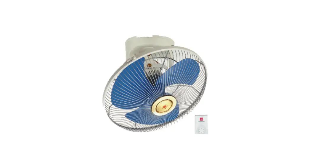
![]() M40R Electric Fan
M40R Electric Fan
Instruction Manual
SPECIFICATIONS
| VOLTAGE (V) | FREQ. (Hz) | POWER (W) | WEIGHT (kg) | |||||||||
| 220 – 240 | 50 | 47.5 – 54.5 | 4. | |||||||||
| Type | Rating | Blade speed of Each position (r/min.) | Power Factor (manly- ) | Rated Air Delivery (m3/min.) | Number of Speed | Fan Size (cm) | Type of Insulation | |||||
| Voltage (V-) | Frequency (Hz) | Input (W) Fan Motor | ||||||||||
| M4OR | 127 | 60 | 67. | 715,825,925,1270,1370 | 0.99 | 86 | 5 | 40 | Functional Insulation | |||
| 220 | 60 | 61 | 610,800,1015,1170,1285 | 0.99 | 84 | |||||||
![]() Use only with rated voltage.
Use only with rated voltage.![]() Before operating this set, please read these instructions completely.
Before operating this set, please read these instructions completely.![]() If the supply cord is damaged, it must be replaced by the manufacturer, its service agent, or similarly qualified persons in order to avoid a hazard
If the supply cord is damaged, it must be replaced by the manufacturer, its service agent, or similarly qualified persons in order to avoid a hazard![]() Ensure that the fan Is switched off from the supply main before cleaning or maintenance.
Ensure that the fan Is switched off from the supply main before cleaning or maintenance.![]() This appliance is not intended for use by persons (including children) with reduced physical, sensory or mental capabilities, or lath of experience and knowledge unless they have been given supervision or instruction concerning the use of the appliance by a person responsible for their safety.
This appliance is not intended for use by persons (including children) with reduced physical, sensory or mental capabilities, or lath of experience and knowledge unless they have been given supervision or instruction concerning the use of the appliance by a person responsible for their safety.![]() To avoid the possibility of causing injury to users or damaging properties, please follow all the 6otplanal m written below. The manufacturer is not responsible for accidents and injuries caused by defective or deficient Installation.
To avoid the possibility of causing injury to users or damaging properties, please follow all the 6otplanal m written below. The manufacturer is not responsible for accidents and injuries caused by defective or deficient Installation.![]() Children should be supervised to ensure that they do not play with the appliance.
Children should be supervised to ensure that they do not play with the appliance.
SAFETY PRECAUTIONS
Be sure to read and follow these safety directions
Be sure to observe the following safety precautions in order to avoid possible injury to yourself or others and damage to your belongings.
The following symbols indicate the degree of possible danger if the relevant precautions are ignored.![]() WARNING This term warns you that death or serious injury may result from incorrect operation of the product.
WARNING This term warns you that death or serious injury may result from incorrect operation of the product.![]() CAUTION This term cautions you that injury or physical damage to property may result from incorrect operation of the product.
CAUTION This term cautions you that injury or physical damage to property may result from incorrect operation of the product.
■ Precautions are classified using the following symbols.![]() The symbol with white background denotes a PROHIBITED action.
The symbol with white background denotes a PROHIBITED action.![]() This symbol denotes actions that are compulsory.
This symbol denotes actions that are compulsory.
![]() WARNING
WARNING
■ Never try to take apart, repair, or modify this product.![]() Do not take apart
Do not take apart
• Contact the dealer for repairing this product.
■ Do not connect the line cord to the outlet until the fan has been completely assembled.
■ Do not connect this unit to a power supply other than destinated country-rated voltage.
Otherwise it may cause fire and injury.![]() Prohibited
Prohibited
■ Do not contact water.![]() Avoid water
Avoid water
Causing fire or electric shock.
■ Do not damage the power cord.
e.g. modify, put near the heat-generating appliance, abnormally twist or bend, forcefully elongate, pull heavyweight, bundle up the power cord.
Causing injury, electric shock, or even fire due to a short circuit.![]() Prohibited
Prohibited
If the supply cord is damaged, it must be replaced by the manufacturer or its service agent or a similarly qualified person in order to avoid a hazard.
■ The safety wire must be always connected.![]() Can cause injury
Can cause injury
■ Ensure that the fixing means for attachment to the ceiling such as hooks or other devices shall be fixed with sufficient strength to withstand 4 times the weight of fan.![]() WARNING
WARNING
■ Disconnect the power supply before cleaning.
Otherwise, it may cause electric shock.
■ Never touch the switch If your hands are wet. May cause electric shock.![]() No wet hand
No wet hand
■ Follow strictly all the instructions given in this manual for installation.
Installation errors can cause fire, electric shock, set to fall, and injuries.![]() Installation must be done by competent personnel.
Installation must be done by competent personnel.
■ Make sure to switch off the switch breaker before installation/repair![]() Can cause the product to suddenly turn on during repairing/installation.
Can cause the product to suddenly turn on during repairing/installation.
■ Do not contact live parts during the installation process.![]() Can cause current leakage and result in fire.
Can cause current leakage and result in fire.
■ If unusual oscillating movement is observed, immediately stop using the fan and contact the manufacturer, its service agent or suitably qualified agent.![]() CAUTION
CAUTION
■ Do not use under the following situations;
- Near to gaseous fuel cooker
- A place full of inflammable gas
- Place expose to rain or water pour
- Near insecticide
- Oil corrosive solvent
- High temperature
- High humidity
- Near chemicals, oil, dust area.
![]() Prohibited
Prohibited
May cause bad effects in quality and dangerous conditions.
■ Don’t place the fan on unstable surfaces or near obstacles.
Risk of injury by a falling fan.![]() Prohibited
Prohibited
Avoid continuous exposure of direct wind from the fan.
It may cause discomfort.![]() Prohibited
Prohibited
■ Do not put your fingers into the guard or any moving part of the fan.![]() Prohibited
Prohibited
Causing injury.
■ Make sure all screws and connections are tightly screwed and secured.![]()
![]() Can cause injury if drops
Can cause injury if drops
■ Installation must strictly follow to wiring diagram provided.![]() Can cause electric shock, current leakage-and fire if missing.
Can cause electric shock, current leakage-and fire if missing.
■ Ensure the area of the mounting fixture has sufficient strength.![]() Can cause injury and product to fall.
Can cause injury and product to fall.
■ Do not fix at area exposed to strong vibration and knocking.![]() Can cause injury and product to fall:
Can cause injury and product to fall:
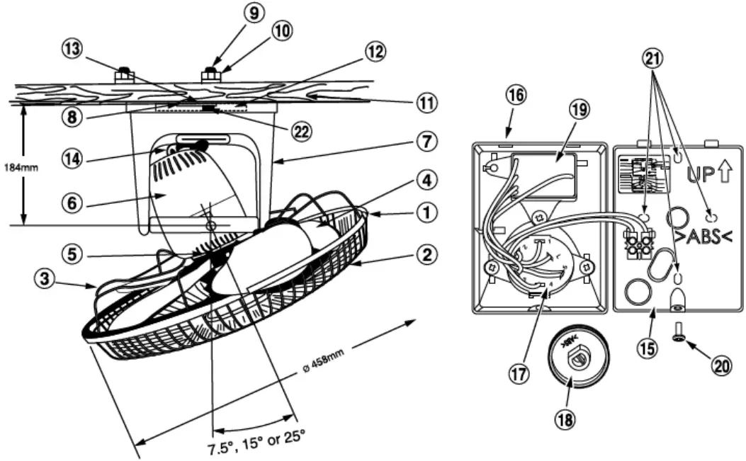
PARTS IDENTIFICATION
ACCESSORIES
H. Bolt (2 pcs)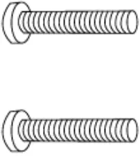 H. Nut (2 pcs)
 Spring Washer
| 1 Plastic clip 2 Front guard 3 Rear guard 4 Blade 5 Wing bolt 6 Motor 7 Stand 8 Mounting plate assy 9 Set bolt 10 Set nut 11 Ceiling | 12 Supporting plate 13 Set screw 14 Rod 15 Regulator base 16 Regulator cover 17 Switch 18 Switch knob 19 Capacitor 20 Cover set screw 21 Fitting hole 22 Safety wire |
HOW TO ASSEMBLE
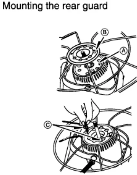
- Align the projection ® with the hole © of the rear guard, and attach the rear guard to the motor.

- Re-tighten 2 wing bolts C.
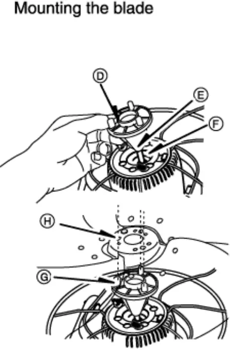
 CAUTION Please ensure the wing bolts are fully tightened to avoid the guard from dropping.
 - Place the blade boss QD onto the shaft, and push it all the way until the groove 0 of the blade boss is correctly fitted to the pin QF of the shaft.

- OD Align the projection © with the hole ® of the blade and attach the blade to the blade boss.
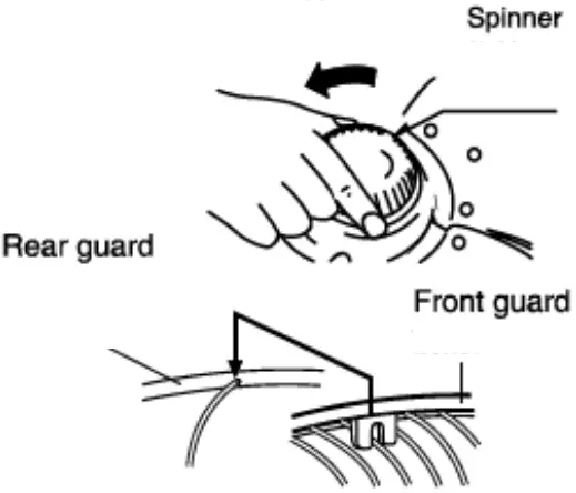
- Next, turn the spinner counterclockwise in order to securely tighten the blade.

- Put rear and front guards together.

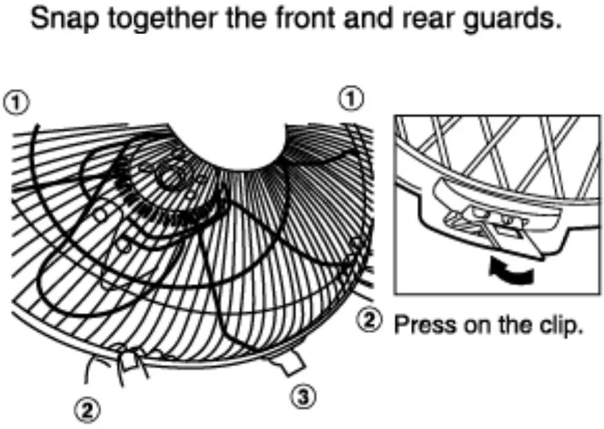
- Snap together the front and rear guards according to sequences 1, 2, and 3.
HOW TO INSTALL THE FAN
![]() Caution
Caution
This fan is specially designed for mounting above 2.3m from the floor. (Mounting height shall be 2.3m)
The mounting of the suspension system shall be performed by the manufacturer, service agent or suitably qualified person.
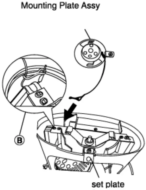
- Remove the set screw and mounting plate from the stand before installing the fan.
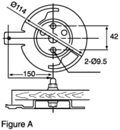
- Install the mounting plate as shown in figure A.

- Hold the stand with the set plate facing towards you and ensure to install the safety wire on the left arm.
Note: Please do not install on the right-hand side. - Loop the safety wire around the arm and clip the wire as shown in B.
 The fan suspension system shall be examined, regularly, at least once every two years.
 - Fix the body to the mounting plate by turning the body so that hole J aligns the screw hole I.

- Tighten the set screw k.
 The fan suspension system shall be examined, regularly, at least once every two years.
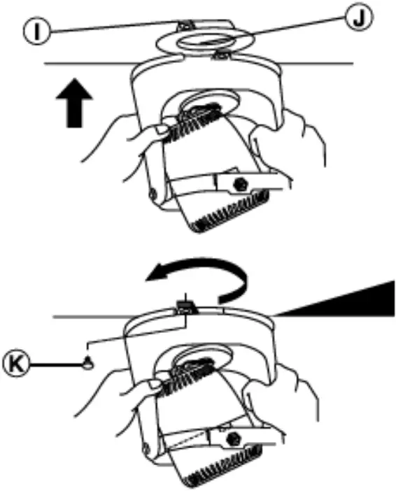
![]() Prohibited
Prohibited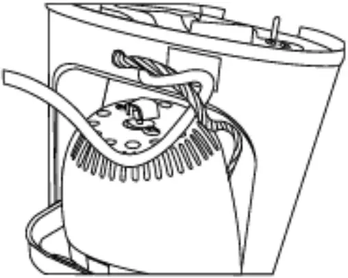 Do not tangle motor lead with the power cord
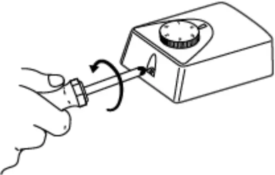
HOW TO INSTALL THE REGULATOR
Caution
This must be a double pole switch with a minimum 3mm contact gap in the fixed installation circuit.
- Disassemble as follows Use a Philips screwdriver to remove the cover set screw.

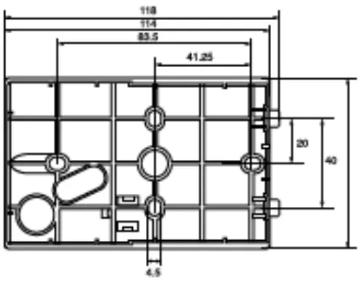
- Fix the regulator base on the wall.

- Ensure that the wiring follows the wiring diagram.
- Reassemble back the regulator above.
Note
The power supply wire connected to the terminal should be equipped with a splice.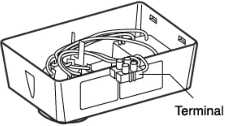
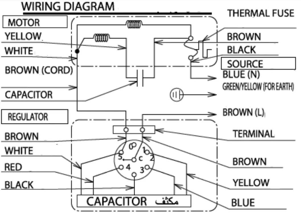
WIRING DIAGRAM
![]() CAUTION
CAUTION
![]() This product is not provided with a cord and plugs with other means for disconnection from the supply. When connecting or changing the power cord or lead wire, it must be performed by qualified personnel in order to avoid a hazard. Please use 227IEC53(RVV) or the thickness of the tube is 1mm or above. (Other requirements such as the diameter of lead wire, please use according to the regulation of the country). This product should be installed with a double poles single throw switch (Breaker Switch) with a minimum 3mm contact gap in the fixed installation circuit.
This product is not provided with a cord and plugs with other means for disconnection from the supply. When connecting or changing the power cord or lead wire, it must be performed by qualified personnel in order to avoid a hazard. Please use 227IEC53(RVV) or the thickness of the tube is 1mm or above. (Other requirements such as the diameter of lead wire, please use according to the regulation of the country). This product should be installed with a double poles single throw switch (Breaker Switch) with a minimum 3mm contact gap in the fixed installation circuit.
OPERATION
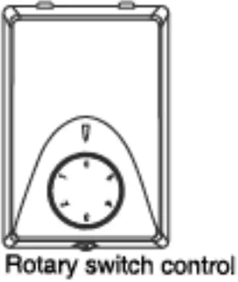
• To turn on the fan, simply turn the switch knob to any positions (1, 2, 3, 4, or 5). To turn it off, turn the switch knob to the (0) position.
ADJUSTMENT OF CIRCULATING ANGLE
The oscillation angle can be adjusted to 15, 30, or 50 decrees.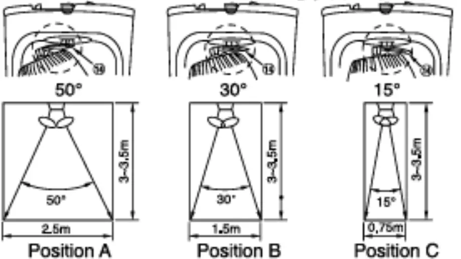 KDK Company, Division of PES
Head Office: 4017, Takaki-cho, Kasugai, Aichi, Japan
![]()


